Deleted
Deleted Member
Posts: 0
|
Post by Deleted on Dec 12, 2010 9:26:23 GMT
sorry you leave me confused Frans, poor regulation, but it don't matter as its class A? maybe I should rephrase this. technical jargon aside, am I likely to HEAR a difference using a toroid vice using the one hifidiy sends with the whole machine kit? location of parts and how easy to get them aside. thanks Confused MaN227 I will explain why, technically, these transformers differ, the sonic consequences are for the more knowingly. The regulation, in other words how MUCH the voltage drops when a higher current is DRAWN from the transformer is important in class AB amps or all other amps where the currents from the load demand more power then is drawn if there is no audio signal. In AB amplifiers (speaker amps) when more power is drawn the power supply voltage drops with this power. IF your amp design is sensitive to these voltage drop on the power supply rails the amps internal workings differ. Now here is the fun part of class A. NO MATTER how much power you draw with the audio (assuming class A currents are not exceeded) the drawn current from the power supply does NOT vary, not even a mV. Aside from the 50Hz AC ripple the DC voltage rails in the amp is CONSTANT. With a low regulation type the 'open voltage' of a transformer is, say, 24VDC (when rectified and without the amp connected) Under a class A operation (always constant max current drawn) the voltage has dropped to 20V DC but is constant. With a 'better' toroid the 'open voltage' of a transformer is, say, 22VDC (when rectified and without the amp connected) Under a class A operation (always constant max current drawn) the voltage has dropped to 20V DC but is constant. The only difference being the extra voltage (thus power in classA situation) is dissipated in extra heat in the low effieciency type. So in practice the toroid runs cooler which in the class A operation is the only difference hence my statement... it doesn't matter. Now for the 'electrical mains garbage' this is another story. Garbage on the mains is usually so called common mode and not so much differential mode which the 50/60Hz is. Power transformers have metal cores that are optimised to be used with low frequencies. Most of them do not convey much energy above 10kHz anymore. This will be about the same for both types of transformers as it is determined by the properties of the used metal (which may be the same type or differ) The leakage currents and transmission of common mode noise from the mains is NOT transferred magnetically by the core but 'conducted' by means of CAPACITANCE. Only differential mode on the mains in the audible range but with much lower amplitudes as the mains is very close to 0 Ohm for low frequencies are transmitted magnetically but will be rectified and not enter the audiopath if the wiring (grounding) is done correctly. When 2 conductors are very near to each other and the contact surface is BIG this acts like a capacitor. the higher the value (surface and proximity) the lower frequencies are conducted. Toroid has primary windings on the inside around the core and the secondary windings are (separated by a piece of plastic) wound directly over them. creating a HUGE surface where capacitive coupling takes place. As the clicks and garbage on the mains is common mode it will be present on the Live and Neutral wire (N having slightly less of it in general). So the toroid couples a WHOLE lot of carbage due to capacitance. With normal type transformers (E core) this capacative coupling is less then toroids as only a small part of the primary is close to a small portion of the secondary and usually separated with a bigger distance too. In case of the Panda transformer (assuming the primary coil is the one on the left and all secondary windings are on the right) the primary and secondary winding are further apart hence less capacity and less coupling of garbage. HOW this all translates sonically remains to be seen and is like everything else in audio open to 'religion'. As stated before leakage currents are 'believed' to affect the SQ in a negative way. In case of class-A the internal resistance (= regulation) of the transfomer is not of importance. I have to say, however, that higher internal resistance is also 'believed' to have sonic impact. The regulation convictions cannot be substantiated by science as we know it. The leakage currents can be clearly shown by science and even with a cheap multimeter. The common mode energy within and WAY above the audible level can disrupt digital circuits and even cause sidebands within the audible FR band which of course can be heard. Nothing a good common mode input filter (when done correctly) can't prevent by the way. ... and stop smoking grass will you ? ... |
|
|
|
Post by gradobob on Dec 12, 2010 18:17:13 GMT
Hi Guys Just an update 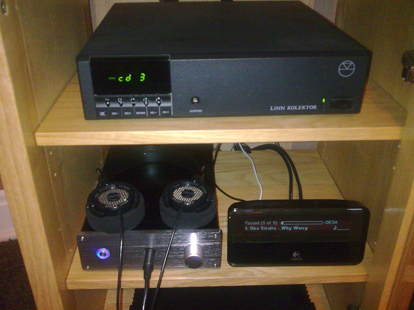 Success -   It was totally due to my inability to wire up the off-board pot correctly.  Thanks to everyone for pointing me in the right direction  Once that had been sorted out, the amp is pretty much silent. At least with the cheep Philips headphones that I was using for testing. With the Grado's I can hear some low level hum which is probably leakage from the torroid. I also own some Sennheiser HD650's, and with these I can hardly hear the hum at all but my first impressions are that the Panda/Grado combo is better suited than the Panda/Senn pair. The only thing left to do is to fit some output resistors. What value would be recommended with the Grado's? |
|
Deleted
Deleted Member
Posts: 0
|
Post by Deleted on Dec 12, 2010 18:46:01 GMT
You will find the hum on the Grado's will be much smaller once output resistors have been fitted and bass will increase.
I recommend 120 Ohm.
The Panda should be completely silent when wired correctly (no hum, no noise).
Did you connect the metal casing to one of the ground pins ?
the 15VAC might still be too low or did you fit another transformer already ?
|
|
|
|
Post by PinkFloyd on Dec 12, 2010 20:54:54 GMT
Also, it's a good idea to run a wire from the body of the pot to the enclosure.... unless you have mounted the pot direct to the chassis? I would definitely solder the heatsinks onto the board and I would go over every single joint with a magnifying glass... it's amazing what a small shard of unwanted solder can do  I fired up panda four yesterday and one of the tip42 transistors went up in smoke.... I spent ages with my multimeter and "nothing"... I eventually resorted to the "magnifying glass" and was amazed to see that there was a small shard of solder shorting out one of the other transistors.... removed it and, VOILA!, she lived! Most problems are related to bad soldering, or should I say "not inspecting the soldering under a magnifying glass".... all it takes is one "hair thin" short across pads and you end up in the crazy factory! It's VERY rare for a component to be at fault.... 99% of the time it's something you've done wrong, or should I say "something you haven't done right"  A hard (smoker's) toothbrush and a bottle of isopropyl alcohol is one of the most important parts of the toolkit.... SCRUB that puppy as hard as you can with a toothbrush flooded with isopropyl.... then get yourself some absorbent kitchen towel:  Flood it with isopropyl and rub it back and forth across the board.... it will shred to pieces, this is cool.... finally, get a dry toothbrush and scrub all the bits of shredded paper off the PCB..... It should be shiny and clean with no traces of anything on it.... just a nice shiny PCB with lovely shiny solder joints. Then get your magnifying glass out and spend 15 minutes scanning the entire board with your eye (top AND bottom) when you are absolutely sure that all is as it should be then, and only then, fire it up. I usually stand well clear when I fire an amp up, I put on safety goggles, a pair of industrial grade (full length) gloves, a pair of Wellington boots, and a safety hat..... I stand 10 feet away and flick the on / off switch with a 10 foot long insulated "pole".... if it doesn't explode I "disrobe" and go over for a closer look  (JOKE!) Mike. |
|
joethearachnid
Been here a while!  Old head on young shoulders.
Posts: 380
|
Post by joethearachnid on Dec 14, 2010 19:10:14 GMT
So my Panda case arrived today: 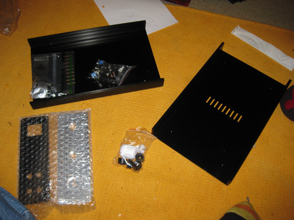 Assembled (for amusement more than any functionality): 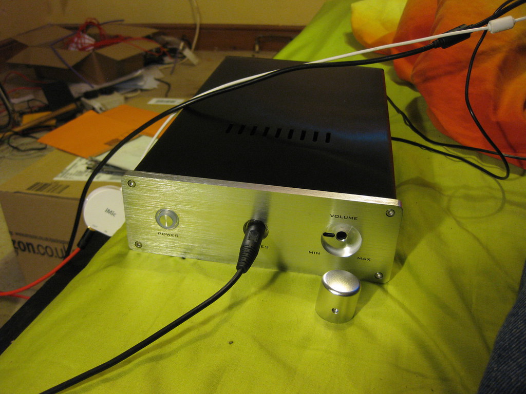 Big excitement! It has vents! They're centred on the bottom panel and forward or back on the top, depending on how you assemble it (I thought forward so it would be nearer the heatsinks). I hope I'm not being a massive idiot, but no other pictures I've seen thus far have had a vented case. Generally the case is wonderfully machined and a real stunner to look at - there are a few scratches on the inside, but that's not really an issue here. It also has more screws than I'm sure I know what to do with, but eh. And a final thing. The little PCB that comes with the rest of the stuff - I assume it's for the switch but I'm not entirely sure of its purpose. I can see how it might be used for connecting the switch to one of the pair of little blue crimp terminals, but then I have another crimp terminal and half the PCB I'm not using. No ideas here. Thanks, -JoetheArachnid |
|
|
|
Post by gradobob on Dec 14, 2010 22:25:49 GMT
It would seem the vents are new, mine certainly doesn't have them The standard of finish isn't great and the front panel material seems as soft as putty, handle with a lot of care if you don't want to end up with lots of little dents and marks. As far as the little pcb is concerned, two pads link directly to the switch so you can use the blue screw terminals for the power switch wiring - I assume the other pads are for mounting the led although I don't think most people have used it, the preference seems to be run a pair of wires direct from the led to the board. Good luck with your build  |
|
|
|
Post by gommer on Dec 27, 2010 20:48:40 GMT
I've also started the build with matching the transistors and FET's I've used 2 methods for comparision. The first measures IDSS (Drain Source saturation current with Gate and Source shorted) with a 9V power supply. Second method used the schematic on next website (on breadboard): www.geofex.com/article_folders/fetmatch/fetmatch.htmSorry, but the picture of interest says it can't be shown outside it's hosting website. I've done 2 runs with this: one with 24V supply (minimum of an LM741) and one with 30V supply (Rset was 15k so with a 30V supply this is very close to the actual working conditions in the Panda). I had 10 FET's delivered with my Panda kit. When i ordered them in function of measured IDSS or Vgs, the order was the same for all runs, but the closest matches were not the same. Vgs method for different Vds values were very close, but this method compared to IDSS measurement gave different results for best matches. With 30V supply, Vgs range was between 902mV and 1074mV IDSS range was between 3,05mA and 3,46mA With IDSS method i had 2 exact matching pairs.One of them was also the best match with Vgs method (only 1mV difference), but the other exact match had a Vgs mismatch of 11 mV, while there were 2 better matches with 5 and 6mV mismatch. This is just a reoprt for all who might be interested. Cheers, Marc |
|
Deleted
Deleted Member
Posts: 0
|
Post by Deleted on Dec 27, 2010 22:03:12 GMT
Hi Marc
Matching FETs is a P.I.T.A. to do properly. Yet another reason why I prefer bipolar transistors at that location. It is not uncommon to replace FETs at that location with matched transistors. The now obsolete matched dual bipolar transistors MAT02 and MAT03 often used to be used for that purpose.Some vendors such as Zhoufang from DIYAudio will sell well matched FETs, but perhaps not the type used here ?
Most people just match them for IDSS, but that doesn't always give you a well matched pair as you have pointed out.
I briefly mentioned similar in an earlier post in this thread.
Alex
|
|
|
|
Post by gommer on Dec 27, 2010 22:19:23 GMT
Well, there are actually good compromise pairs that match both methods. So i presume they wil effectively be good matched pairs.
Only minor problem is they are at opposite ends of the scale, so i'll have a channel mismatch, but IMO that's less of a problem.
|
|
|
|
Post by nisbeth on Dec 29, 2010 21:04:01 GMT
Quick question before I jump on one of the Panda kits as well: How high are the caps and the heat sinks above the board? Just wondering if I can squeeze this into a 1U case  /U. |
|
|
|
Post by PinkFloyd on Dec 29, 2010 21:30:56 GMT
OK.... the measurements are in.... the caps are 35mm tall, the board and soldering you should leave another 5mm for.... personally, 50mm would be the minimum internal cabinet height I would use.
|
|
joethearachnid
Been here a while!  Old head on young shoulders.
Posts: 380
|
Post by joethearachnid on Jan 7, 2011 0:40:31 GMT
Okay, the good news: My Panda kit finally arrived after just over a month in limbo. Apparently customs finally decided to 'receive it' yesterday (Wednesday) at about 7pm. Spent all of 2 minutes (!) in customs. I think I was right when I thought that they're really shovelling stuff through right now. I was especially happy to receive the kit now that it seems like the Panda is becoming an endangered species among salespeople. And now for the bad news: the Panda is assembled, but currently non-functional. Not even a blip. I managed to get something like 0.002v across the LED terminals but nothing else, nothing at all across the two 1.5k resistors, apparently not even an AC voltage across the trafo, though I think that's due to my incompetence of not really knowing how to measure AC voltages anyway. Yes, the power was switched on.  I was going to spare you my terrible soldering, but it seems like I don't have a choice: 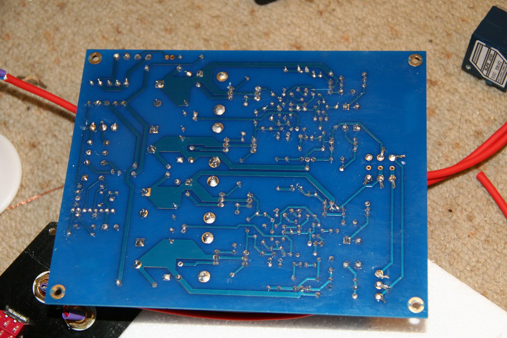 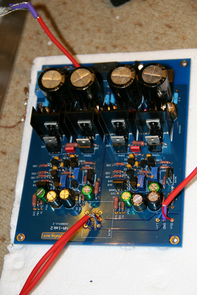 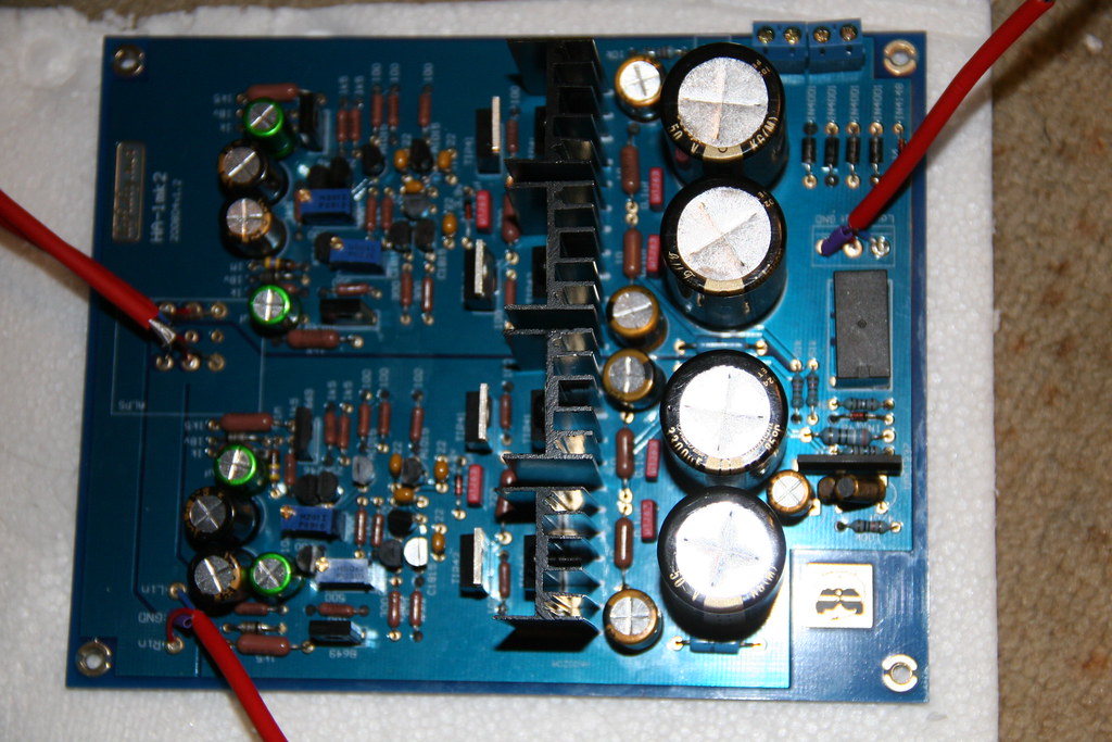 (the two bumming caps in this one are soldered in properly, they just don't fit flush and got a bit bent) 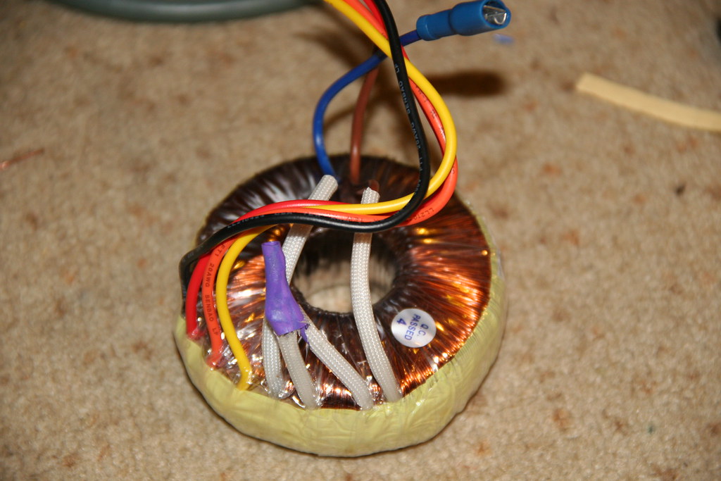 Here's the transformer. I connected the purple and grey wires together, and wired the secondaries to the Panda as per Mike's colour guide. Since there really doesn't seem to be a peep at all I'm thinking perhaps something is wrong with the power section. Not an expert obviously, but that's where I'd look if I wasn't so bloody tired. I know of a few other faults, such as some slightly wonky wiring on the pot (which is offboard, since I felt it was less effort/money than an extension rod) that I'll deal with tomorrow. I'd like to get the amp working full stop before I weed out things like that, though. Thanks in advance. I thought maybe I'd be lucky and get it going first time, but not even Mike was able to do that. Such is DIY electronics, I guess.  -JoetheArachnid |
|
|
|
Post by gommer on Jan 7, 2011 15:01:49 GMT
Maybe a stupid question, but have you wired the secondary transformer windings correctly? If one of the two is in reverse 'polarity' to the other, they will effectively cancel each other out.
|
|
joethearachnid
Been here a while!  Old head on young shoulders.
Posts: 380
|
Post by joethearachnid on Jan 7, 2011 18:20:09 GMT
She lives!
Turns out that the f*&king buggerwanking fuse had gone in the IEC cable (not the amp inlet). No wonder I wasn't getting any AC readings! I'll be adjusting the 1.5k resistors and the DC offset now, and then I'll see if there are any listening problems. Otherwise I'll case 'er up and hopefully be able to have a good listen this evening.
-JoetheArachnid
|
|
joethearachnid
Been here a while!  Old head on young shoulders.
Posts: 380
|
Post by joethearachnid on Jan 7, 2011 19:13:28 GMT
Okay, just another slight issue here...
I currently have NO DC offset. At all. I can't seem to coax one by twiddling the 200R trimpots either. I seem to remember Frans having another method to find the DC offet that works with unmatched transistors, but can't find it. Any ideas?
There's also no sound. Don't know if that's 'cause of the DC offset or what.
-JoetheArachnid
|
|
Deleted
Deleted Member
Posts: 0
|
Post by Deleted on Jan 7, 2011 19:27:31 GMT
|
|
joethearachnid
Been here a while!  Old head on young shoulders.
Posts: 380
|
Post by joethearachnid on Jan 7, 2011 20:26:43 GMT
Okay, she lives... and plays music this time!
Time to get casing. Frans, you are a god of the Dutch variety.
-JoetheArachnid
|
|
joethearachnid
Been here a while!  Old head on young shoulders.
Posts: 380
|
Post by joethearachnid on Jan 8, 2011 0:51:20 GMT
Dang. I mean, DANG. I know what other people have said, but that still didn't prepare me for what this little bugger can put out. I was half expecting some kind of bloated bassmonster from what people had described, but what do I get? - Tight, crotch-clenching bass that goes down to the earth's core, yet doesn't overshadow the other elements.
- Intoxicating, liquid mids that you want to drown in.
- Treble clarity like a knife's edge but delicate and refined at the same time.
- Dead silence across all but the highest volumes - and all my cans are sensitive and between 16-50ohms impedance.
- Not being a useless electronics brick despite my best efforts otherwise.
Colour me impressed. I'm officially putting this on the 'Best £X I've ever spent' list at the £50 mark. One (just one) problem though - this amp is currently unsafe, as the case is not grounded to the mains. When I attach the earth wire to the case I get osciallting noise - which I assume is mains noise. I think the problem may be that I'm using an Neutrik 'barrel' socket that Mike sent me - it's just fitted straight against the front panel, and being entirely metal I assume that this connects signal ground to mains ground. I asked Mike and he didn't think it would be a problem, but apparently the amp has other ideas. So, what's the best course of action here? I have a non-metal-bodied socket if I need to pull this one out (but I'd rather not), so is there any easy way to insulate it? 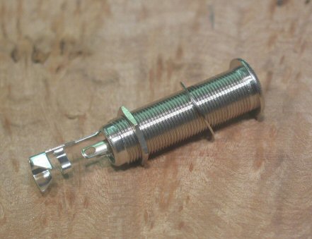 |
|
Deleted
Deleted Member
Posts: 0
|
Post by Deleted on Jan 8, 2011 13:17:11 GMT
a single wire from one of the GND connections of the board to the metal casing SHOULD make the amp totally quiet.
With just a single toroid you would not be needing a grounded mains cable.
IF you have a mains filter installed or made one yourself with parts and some of these parts are connected to ground, these wires should also be connected to the chassis AND you will have to use a grounded mains connection.
Are the input RCA's also connected to the chassis or isolated ?
|
|
joethearachnid
Been here a while!  Old head on young shoulders.
Posts: 380
|
Post by joethearachnid on Jan 9, 2011 14:31:51 GMT
Hmm. After some experimentation it seems that the problem is just a good old-fashioned ground loop. It was the fact that the noise only came when I attached my source that twigged it for me.  Serves me right for using a crappy USB DAC, I suppose. So the current options are to use a different source (I don't have any others that are convenient right now), to use my laptop on battery power whenever I want to use the amp (also rather inconvenient) or to leave the case ungrounded for now. I'm not partial to this option because I've already managed to shock myself twice (!) today, but I'm fairly confident in my wiring and all 240v AC connections have been insulated with heatshrink and hot glue. Any ideas? -JoetheArachnid |
|
Deleted
Deleted Member
Posts: 0
|
Post by Deleted on Jan 9, 2011 14:56:16 GMT
the casing MUST be connected to one of the GND pins on the board. If it isn't the amp will be sensitive to garbage from outside and possibly hum when touching the casing. You don't need to ground the housing to safety ground when you have NO additional filtering and only have the primary of the transformer connected to the inlet. When you have filtering installed on the mains to ground you MUST use a 3 pin mains wire and must connect it to a 3pin (grounded) mains socket. The amp should be totally silent and no noise should appear connecting it to any device. If it does you have not been carefull with grounding. If you have shocked yourself there must be something not wired up correctly or you grabbed the mains. The latter is far from recommended.  Post a clear picture of the insides of the cabinet. |
|
joethearachnid
Been here a while!  Old head on young shoulders.
Posts: 380
|
Post by joethearachnid on Jan 9, 2011 15:30:11 GMT
To clarify: Yes, the ground of the board is definitely connected to the chassis. Checking with a DMM shows a >1ohm resistance between signal ground and anywhere on the chassis. I understand now that this was not the problem, the mains noise problem occurs only when the IEC ground is attached to the chassis and my USB DAC source is connected, and this is only when my laptop is plugged in. Other sources (like my iPod) are dead silent across the board. There's some faint hum at full volume but I think this is more to do with 112dB sensitivity headphones rather than any shielding issues. From this I assume that it's a dreaded ground loop. Also the electrocution was my own stupidity, not due to any bad wiring. For some reason when plugging in the IEC cable the best option for holding the chase seemed to be holding the INSIDE of the IEC socket. Not a good plan. Here is a picture, though I'm not sure how helpful it will be: 'Pandemonius Ignavus' (Lazy Panda) 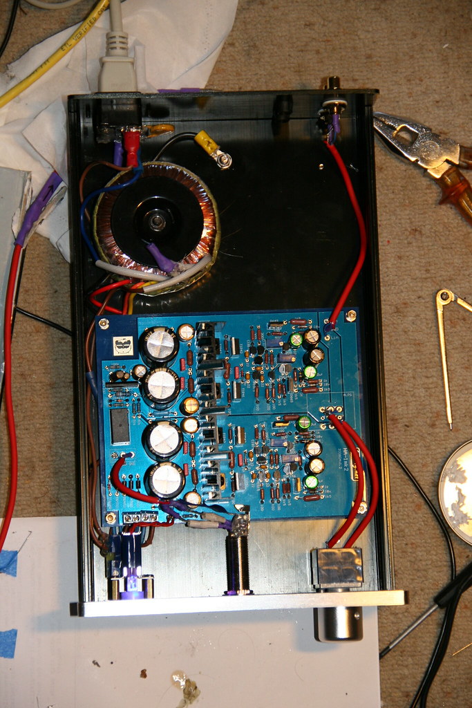 -JoetheArachnid |
|
Deleted
Deleted Member
Posts: 0
|
Post by Deleted on Jan 9, 2011 16:08:45 GMT
I take it the varistor or cap is across the L and N ?
To brake the ground loop you could connect the safety ground of the mains by inserting a 1k resistor between the casing and the mains ground.
Unorthodox but worth a try.
|
|
joethearachnid
Been here a while!  Old head on young shoulders.
Posts: 380
|
Post by joethearachnid on Jan 9, 2011 16:49:26 GMT
Yeah, the varistor is across L and N, as Mike suggested. It seemed like something easy that I could do that could easily pay off later. Hmm, that sounds like a plan. Pity I have no 1k resistors around. Is that the maximum that could be put in there whilst still working as a safety short? I assume I'd need some fairly high-wattage resistors. It seems strange to have to modify the amp to compensate for a problem with my source, but then again it's insurance. I'll see about getting hold of some resistors - I assume that they don't have to be 0.0001% in this case?  There are plenty of cheap 5W wirewound/ceramic ones that I hope would fit the bill. I don't suppose that there are any othing things that can be put between ground? Polar caps, diodes etc? Thanks for all your help. I'm going to try and get some extended listening in for now, and leave the Panda in 'dangerous' (no mains ground) mode for the time being. It's worth risking death for sound this good. -JoetheArachnid |
|
|
|
Post by PinkFloyd on Jan 9, 2011 20:38:36 GMT
- Exactly what specs should I look for for the toroidal transformer (is 50VA, 115/230V, 2x18V correct)? Also, would an encapsulated toroidal transformer be better to use in terms of humming/interference? 30VA is the minimum I would use, I prefer 50VA (50VA 0-18V 0-18V) Dual primary 115+115V. Frans prefers 120 ohm, I use 75 ohm but there really isn't a lot in it.. with the DT-770 I would tend to go with 75ohm (metal film are fine but if you want something a bit more exotic try Kiwame , carbon composites etc.) It's better to go with +6db from the start (ie: replace the 300R resistors with 150R resistors) It gives better control on the volco... with standard gain you have to crank the volco quite high to get normal levels.... +6db is just about right IMO. |
|


