Deleted
Deleted Member
Posts: 0
|
Post by Deleted on Nov 7, 2010 17:09:55 GMT
Mike, have you measured the output in mW of this amp? Thanks. What output resistors does it have and which HP (impedance) do you want the numbers for. The power levels are dependant of those 2 values. Here are the powers for a Panda with a NO (0 Ohm) output resistor (rounded off values): HP impedance ....Class-A......Class-AB 32 Ohm ..............640mW.......3,125mW 64 Ohm ..............1,280mW ...1,560mW 150 Ohm ............670mW ......670mW 300 Ohm ............330mW ......330mW 600 Ohm.............170mW ......170mW Here are the powers for a Panda with a 10 Ohm output resistor (rounded off values): HP impedance ....Class-A......Class-AB 32 Ohm ..............640mW.......1,800mW 64 Ohm ..............1,170mW ...1,170mW 150 Ohm ............580mW ......580mW 300 Ohm ............310mW ......310mW 600 Ohm.............170mW ......170mW Here are the powers for a Panda with a 22 Ohm output resistor (rounded off values): HP impedance ....Class-A......Class-AB 32 Ohm ..............640mW.......1,100mW 64 Ohm ..............640mW ......870mW 150 Ohm ............510mW ......510mW 300 Ohm ............290mW ......290mW 600 Ohm.............160mW ......160mW Here are the powers for a Panda with a 47 Ohm output resistor (rounded off values): HP impedance ....Class-A......Class-AB 32 Ohm ..............500mW.......500mW 64 Ohm ..............500mW ......500mW 150 Ohm ............380mW ......380mW 300 Ohm ............250mW ......250mW 600 Ohm.............140mW ......140mW Here are the powers for a Panda with a 75 Ohm output resistor (rounded off values): HP impedance ....Class-A......Class-AB 32 Ohm ..............280mW.......280mW 64 Ohm ..............330mW ......330mW 150 Ohm ............300mW ......300mW 300 Ohm ............210mW ......210mW 600 Ohm.............130mW ......130mW Here are the powers for a Panda with a 120 Ohm output resistor (rounded off values): HP impedance ....Class-A......Class-AB 32 Ohm ..............140mW.......140mW 64 Ohm ..............190mW ......190mW 150 Ohm ............200mW ......200mW 300 Ohm ............170mW ......170mW 600 Ohm.............120mW ......120mW So pick your headphone impedance and you will have a pretty good idea. NOTE: Most headphones can handle a power of around 100mW to 200mW. You can clearly see that a higher output resistance of the amp leads to safer values for all headphones where 0 Ohm or low Ohmic values can seriously overdrive (destroy) low Ohmic headphones !  High Ohmic headphones are always in the 'safe zone' with this amp. Amps with a 120 Ohm output resistor in the output are also always in the 'safe zone'. Some headphones, however, perform sonically better at lower output resistances but you must be aware that these low output resistance values can destroy low Ohmic headphones. |
|
Deleted
Deleted Member
Posts: 0
|
Post by Deleted on Nov 7, 2010 17:36:48 GMT
Can someone please tell me what voltage is best to use for the LED.
5 VOLT 5mm LED or
12 VOLT 5mm LED.
Thanks.
Mick.
|
|
Deleted
Deleted Member
Posts: 0
|
Post by Deleted on Nov 7, 2010 18:07:34 GMT
a LED doesn't work on a voltage but current.
This current is determined by a resistor that must be in series with the LED.
The voltage drop over this resistor determines the current.
IF you plan to use a LED on the Panda board just use the LED connector on it.
It already has a resistor installed on the board (right next to it in fact)
most LED's work fine between 5 and 15mA.
There are also LED's that work on 1 or 2mA and high brightness LED's need bigger currents.
the mm are not of importance (1 to 8mm)
|
|
|
|
Post by clausdk on Nov 7, 2010 21:06:20 GMT
I got a Panda running without output resistors and it drives the Ergo AMT nicely, I guess they have about the same powerhunger as the K1000   would bigger cooling fins add to the SQ ?? Would a commen heatsink be better (keeping the Transistors at the same temperaure) ?? |
|
Deleted
Deleted Member
Posts: 0
|
Post by Deleted on Nov 7, 2010 22:19:01 GMT
Adding heatsinks will do nothing to the sound.
If it plays well with the Ergo without output resistors and the heatsinks do not get excessively hot (nor the 10 Ohm resistors) and it plays loud enough as it is... just leave it that way.
Keep it exclusively for the Ergo.
Low Ohmic headphones can easily be destroyed without output resistors.
The temperature of the 4 heatsinks should be the same anyway.
a standard Panda without output resistors can drive a 4 Ohm headphone but will only be driven 16 mW in Class A and the panda will actually always be in class AB.
It can deliver 3V into 4 Ohm which is 2.25W in class AB.
When the amp is modded with the 2.2 Ohm in parallel to the 10 Ohm and the zenerdiode is altered (the 1.5V bias must probably be set smaller too ?) the amp could deliver 6.5V into 4 Ohm which is 10W in class AB but the heatsinks must be made bigger.
With 200mA idle current it would deliver about 0.1W in class-A
|
|
mrarroyo
Been here a while!  Our man in Miami!
Posts: 1,003
|
Post by mrarroyo on Nov 8, 2010 11:37:23 GMT
Has any of you crazy guys thought of building a unit with two boards so it would output in balance mode?
|
|
Deleted
Deleted Member
Posts: 0
|
Post by Deleted on Nov 8, 2010 13:12:54 GMT
On the toroid Mike has sent me there are 4 primary wire:- Blue Grey Purple Brown. 0v 115v 0v 115v I take it that i should use Blue( neutral) Brown (positive). Are the Grey and Purple joined together, or blanked off individually. Thanks Mick. Correct ! |
|
Deleted
Deleted Member
Posts: 0
|
Post by Deleted on Nov 8, 2010 13:16:34 GMT
Thanks Frans, it would seem the 22 ohm provides a big bang for the buck if the power in class a is used as a basis of comparison. Did I read the table correctly? Yes you read correctly, but not all headphones like to be driven from 22 Ohm so that's why my TX amp has 20 and 110 Ohm outputs. You can indeed make a balanced one and the class-AB power rating will go up (almost factor 4) but the class-A power rating will remain the same. You could seriously damage headphones with a symmetric Panda. |
|
|
|
Post by PinkFloyd on Nov 8, 2010 13:39:45 GMT
On the toroid Mike has sent me there are 4 primary wire:- Blue Grey Purple Brown. 0v 115v 0v 115v I take it that i should use Blue( neutral) Brown (positive). Are the Grey and Purple joined together, or blanked off individually. I am asking because the other toroid i used had just a Blue and Brown on the Primary side. Thanks Mick. OK.... for 230V duty connect the grey and purple together... blue is neutral, brown is live. For 115V duty you would connect blue and purple together and grey and brown togerther. Blue + purple = neutral and Grey + Brown = live. Mike. |
|
|
|
Post by Koolind on Nov 8, 2010 17:21:01 GMT
Thanks Frans, it would seem the 22 ohm provides a big bang for the buck if the power in class a is used as a basis of comparison. Did I read the table correctly? Yes you read correctly, but not all headphones like to be driven from 22 Ohm so that's why my TX amp has 20 and 110 Ohm outputs. You can indeed make a balanced one and the class-AB power rating will go up (almost factor 4) but the class-A power rating will remain the same. You could seriously damage headphones with a symmetric Panda. So what you are saying is that you dont think that it would have any sonic advantages to "make it balanced" ? (not that i am considering it right now) It would be a cool option to have though  |
|
Deleted
Deleted Member
Posts: 0
|
Post by Deleted on Nov 13, 2010 9:54:30 GMT
Hi Leo
well i did get bored and try the j309 set for about 8ma. my j309 have a huge IDDS range 13.5ma to 20.2ma so quite a variation.i just grouped four close ones.
how does it sound?
clearer and more focused I'd say, the bass still goes as deep but sounds clearer and more tuneful IMHO. yes not a huuuuge difference but a nice touch and worth the effort.
i have trouble translating from tubes to solid state and it's still a puzzle to me sometimes. i have used gas zeners lots before so know where you are coming from. i thing it might be worth using trimmers on each jfet and just dialing in the required voltage but thats o bit OTT maybe.
THANKS
take care
|
|
|
|
Post by PinkFloyd on Nov 17, 2010 20:33:48 GMT
. Any chance Mike, you can give electronically challenged people like me a fuller explanation on what is required, and how to go about matching the components, using a battery and Meter.  Mick. Hi Mick, Give me a while to come up with a diagram..... Basically I use a dil8 socket (but only use three of the sockets, the other 5 sockets I infill with solder).... it's simply a case then of connecting the negative lead from your PSU of choice (battery or regulated PSU) to two of the sockets, Com lead of your multimeter to the other socket and input lead of the multimeter to positive (power supply)... you then set your multimeter to the mA range and plug the transistors into the three sockets as shown.... Pretty easy  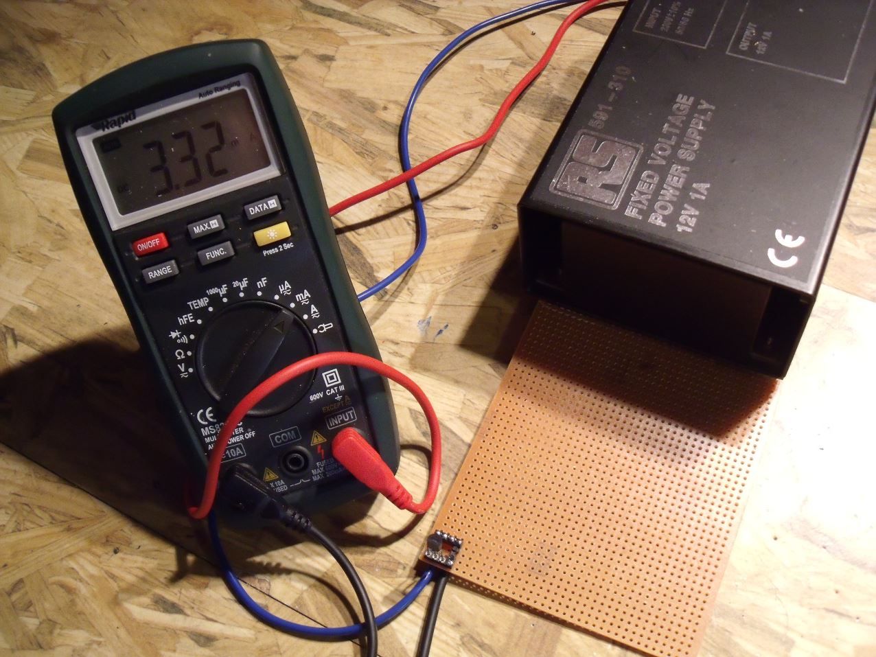 Once I have taken a measurement I mark the results on a piece of paper then stick the transistor underneath it with sellotape: 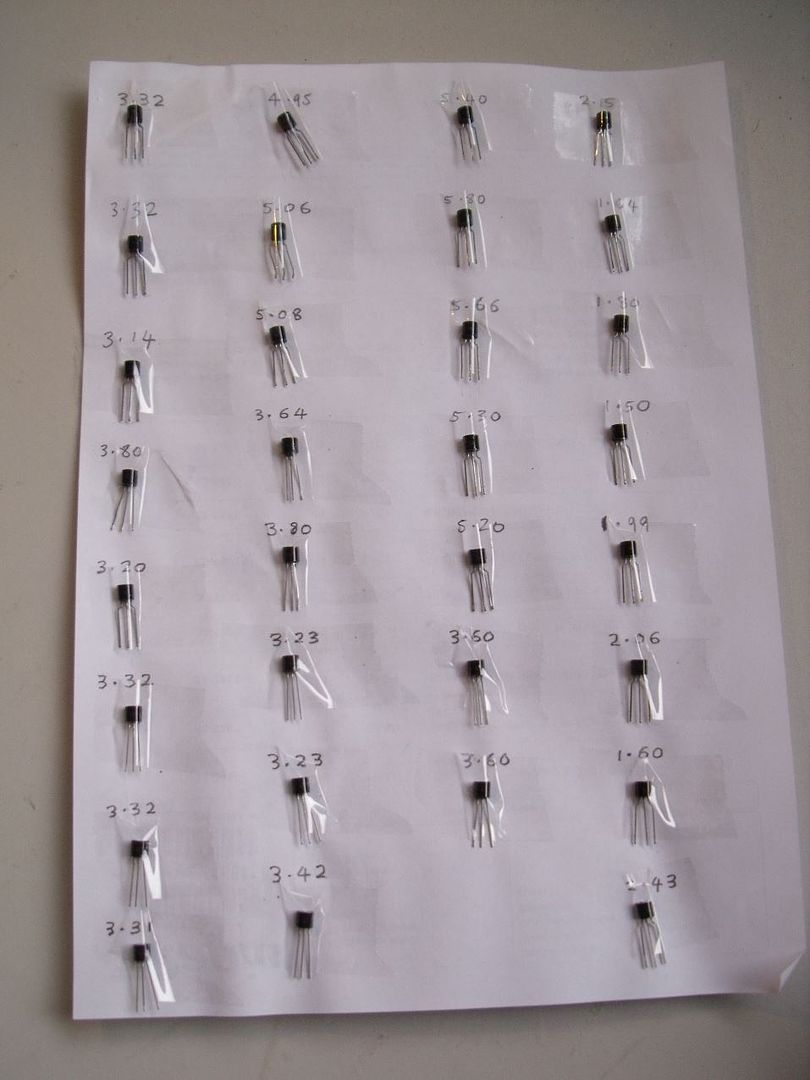 When I have time I'll draw a diagram to show you how to hook things up. Mike. |
|
|
|
Post by PinkFloyd on Nov 29, 2010 23:53:53 GMT
Couldn't help myself, just had to try a few alternative caps now I've lived with it as stock for a while , nothing mad just a few swaps. This thing really responds to different parts  Please divulge Leo  Mike. |
|
leo
Been here a while!  Team wtf is it?
Posts: 3,638
|
Post by leo on Nov 30, 2010 0:21:11 GMT
Nothing major yet , first was the 1N400* type rectifier diodes to faster types, brought a small but noticeable difference. I've also refitted the CRD's, tbh I still prefer them over the 1k5 resistors. I couldn't understand why they fitted those 10uf NP caps in the regulator (on the transistors base) , I always thought those would be better suited to coupling than decoupling so I've fitted temp sockets, just tried 4.7uf Wima film caps. Quite surprised what difference those made, just running in , 10uf films was too big to fit May try an alternative to the 220uf's Nichicons across the input of the regulation in the output section , maybe 100uf FM, dunno yet. Trying to get that bass tightened up a little  |
|
Deleted
Deleted Member
Posts: 0
|
Post by Deleted on Dec 4, 2010 20:49:39 GMT
Hi guys Although I've had my Panda kit for quite a while, I just got around to starting to put it all together. But I'd appreciate a bit of advice regarding a couple of issues I've found. Firstly, I got just the right amount of parts - no spares but no shortages either. But I thought in any case I'd check the FET's to try and match them up as best I can. So I've put together a little test jig using a PP3 9V battery as power source, but I can't get any readings from any of the 3 or 4 FET's I've tested. I've checked and double checked that I have the jig wired corectly and there's definitely 9V going across the transistor. I am using the mA connectors on the multimeter but the arrangement on my meter is different from how you show it set up - according to the manual for my meter it's Black to Com and Red to mA or A. Could this be because I'm using a PP3 battery? Secondly, I've just discovered that one of the big power caps (3300uF) has a dent in the side - I assume that this means it's knackered - correct? Bob Did you short (connect) the Gate and Source of the FET's ? Often the multimeter (m)A range is fused and if the fuse is blown no current will/can flow. a dent doesn't mean it's knackered. Is the dent sharp ? Is the metal pierced ? Is the dent relatively deep ? It might still work normally. You can only find out if it still works by connecting it to a power supply (30 - 35V). Electrolytic caps are 'self repairing' in principle. If there is a short-circuit inside between the foils the part where it is shorted simply burns away and it works normal again. However, If you can get a spare from the seller I would prefer that myself. |
|
|
|
Post by gradobob on Dec 5, 2010 22:24:53 GMT
Hi Frans You were correct, the fuse had blown inside the meter. Thank you for pointing me in the right direction. Regarding the capacitor. As the dent hadn't pierced the can and was fairly shallow and encouraged by your comments that it may still work ok, I've finished populating the PCB and I've fitted the dented cap. So far, so good. I've powered up without any fireworks and the little relay clicks after a second or so. I've been able to adjust the voltage across the two 1k5 resistors to 1.2v without any dramas. I've also adjusted the DC offset on both channels to <1mV All that remains is to plug some cans in and see if it works with music  |
|
Deleted
Deleted Member
Posts: 0
|
Post by Deleted on Dec 5, 2010 22:47:47 GMT
I would adjust the 1k5 resistors to 1.5V (and then might have to readjust the DC offset again)
the 1.2V is too low actually and the output transistors simply are not biassed as good as can be.
Info on it is somewhere in the big Panda thread.
don't forget the al important output resistors that are NOT on the board.
Don't have much experience with Grado's but they seem to do well on a 120 Ohm output, just like AKG and a lot of other cans.
Enjoy the Panda, it's an excellent amp.
|
|
Deleted
Deleted Member
Posts: 0
|
Post by Deleted on Dec 6, 2010 15:22:30 GMT
check the voltages on the Emitter of Q3 and Q22.
They should be around 17-17.5V.
If it's much higher it is very likely you blew Q3 or Q22 when adjusting the 1.5V
When your testlead slips of the pad and touches the ground plane at the same time you blow the 2SD669.
Just replace it.
If you can't easily get this part let me know
|
|
|
|
Post by gradobob on Dec 6, 2010 22:19:06 GMT
I've checked the emitter voltages on Q3/Q22 as suggested. I get 16.9v on left channel / 16.8V on right channel I was very careful when setting the voltage across the 1k5 resistors, I clipped insulated test probes in place before switching the amp on, although it is very tight in that area so there was always a chance of something happening. Anyway, I've reflowed most of the points on the left channel and now I have bad hum in both channels  I've attached a couple of photos in the hope that someone may be able to spot what I've done wrong  Sorry about the camera phone quality, it's the only thing I can lay my hands on atm 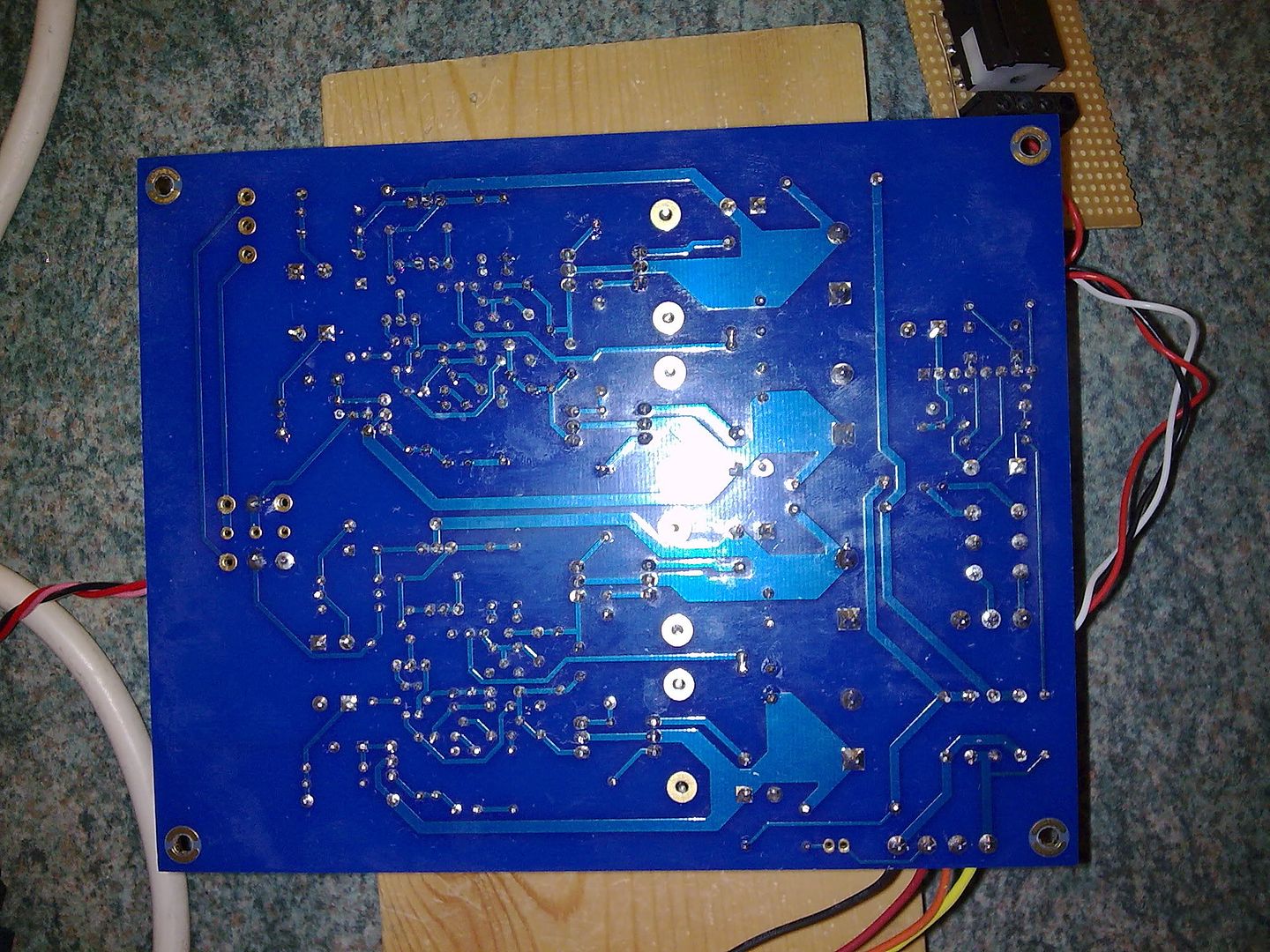 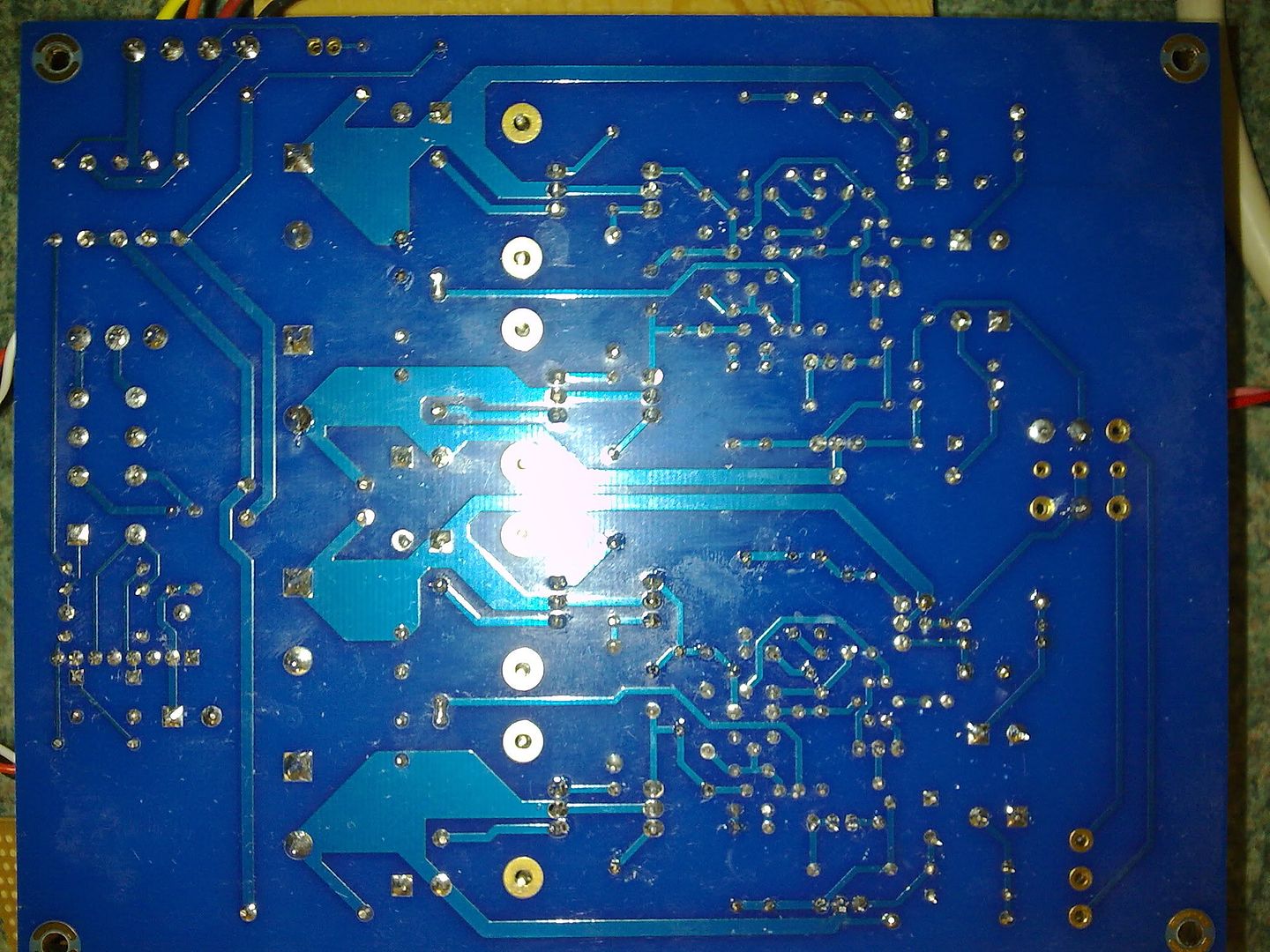 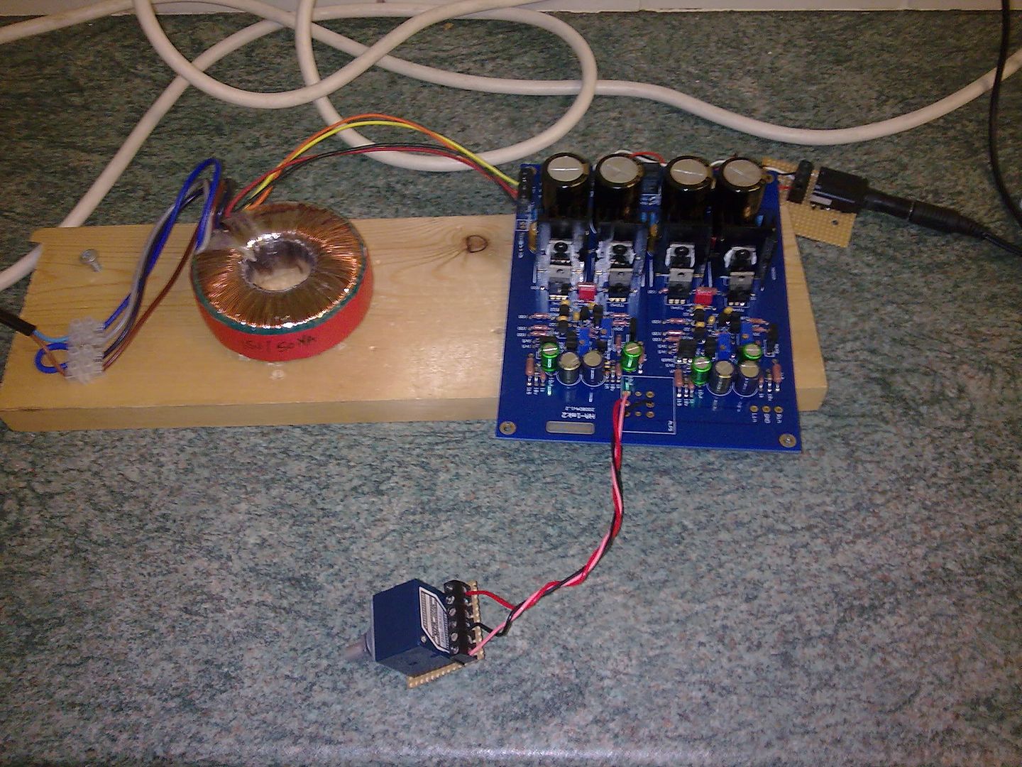 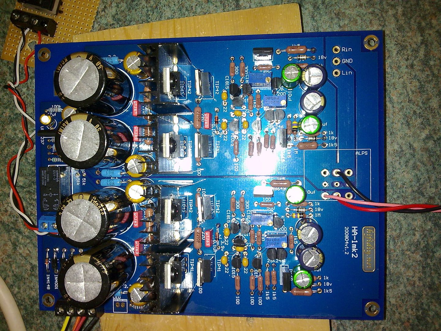 thanks |
|
|
|
Post by PinkFloyd on Dec 6, 2010 22:37:23 GMT
Maybe me looking at a 10 inch screen but I think the problem lies in the way you've hooked up the pot? Just doesn't look right to me.
|
|
Deleted
Deleted Member
Posts: 0
|
Post by Deleted on Dec 7, 2010 1:19:17 GMT
Hope this helps..  You basically need six connections, as far as I can see you have only three. The pot has six pins that would make all six connections directly to the board. You need to copy that via the cable connections. R in R out L in L out Earth in Earth out |
|
|
|
Post by gradobob on Dec 7, 2010 22:36:59 GMT
I've tried a few things tonight but not made any progress I am getting 22v DC across the ps caps and I've taken the bias voltage? across the 1k5 resistors down as far as it will go (0.95v and 1.05v) but the hum is still there 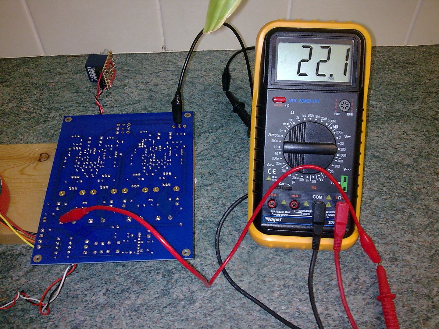 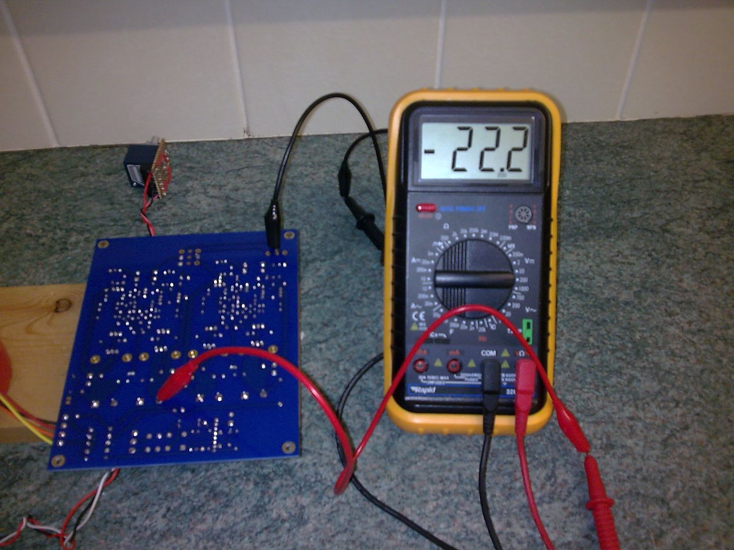 I've checked the pot wiring and added an extra ground wire but again still plenty of hum 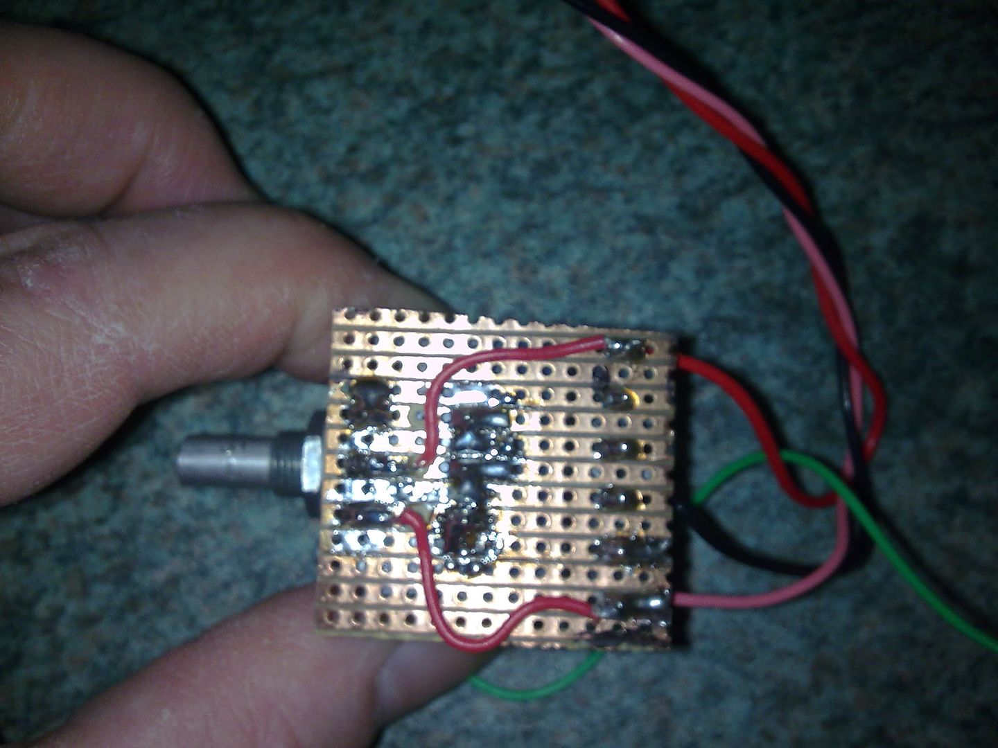 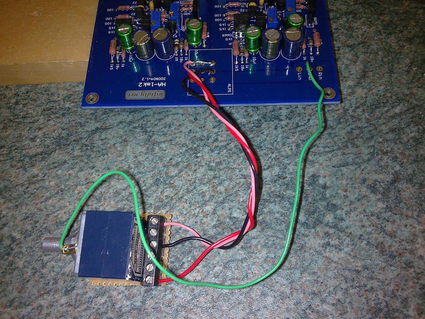 I've also checked the emitter voltage on the D669 which both still read almost 17v and also the B649 which are both about -17.5v Very sad now  |
|
Deleted
Deleted Member
Posts: 0
|
Post by Deleted on Dec 10, 2010 7:18:53 GMT
If you want a power transformer with the lowest possible leakage current, which is recommended if you do not connect the ground/casing of the Panda cabinet to safety earth (for instance by using a 2pin wall socket for feeding hifi) this is the best you can get. Some believe leakage affects SQ. I know it can prevent 'clicks and ticks' from other appliances in the house from entering this amp.  |
|
|
|
Post by mingo on Dec 11, 2010 13:45:36 GMT
Claus will send me 2 Panda kits in the near future.
My headphones are
Sennheiser HD 800
AKG K701
Superlux HD 681 modified by Frans (filter version 1)
My questions are:
1. What kind of changes (if any) compared to the original kit will I have to implement in order to get the most out of my Sennheisers?
2. Will that Panda be able to get the most out of my other phones, or will I have to make slight changes compared to 1?
I have never tried to build kits before, so I shall need all the help I can get.
I am aware that various changes have been mentioned in the course of time, but I am not sure which ones will work with my phones.
Thank you for taking the time to reply.
|
|
Deleted
Deleted Member
Posts: 0
|
Post by Deleted on Dec 11, 2010 14:46:25 GMT
120 Ohm output resistors, the Sennheiser HD800 and K701 will love it.
Superlux does best at around between 50 and 80 Ohms bit will also do pretty well on 120 Ohms
the 1k5 resistors voltage should be set at 1.5V.
You can make 1 stock and 1 modded with whatever you can find.
|
|


