Deleted
Deleted Member
Posts: 0
|
Post by Deleted on Oct 13, 2010 9:51:49 GMT
Please can we use this thread, for posts and replies, appertaining to the build, problems associated with, and mods to this Amp only.
Thank you. 
Mick. EDITED. To save those interested from searching right through the thread for a schematic, I have attached a copy. Alex

|
|
Deleted
Deleted Member
Posts: 0
|
Post by Deleted on Oct 13, 2010 12:57:40 GMT
Whilst assembling my enclosure i noticed that the top half had a slight crease(or dent) in it, that could only be seen when the light caught it at the right angle,a bit like a car park ding in your door, when the women in the car parked next to you opens and rests her door against yours whilst loading her children into their seats, didn`t bother her at all that i was sitting in my car watching, yes leaves a dent that can be seen when the light hits at the correct angle. As the bottom half of my enclosure is totally unmarked, i decided to change them over, drilled and tapped the top half for the 4 rubber feet, counter sunk the original holes in the bottom and screwed in 4 C/S screws allen screws. At least the four screws that are now in the top look like they should be there, where as the dent certainly did not  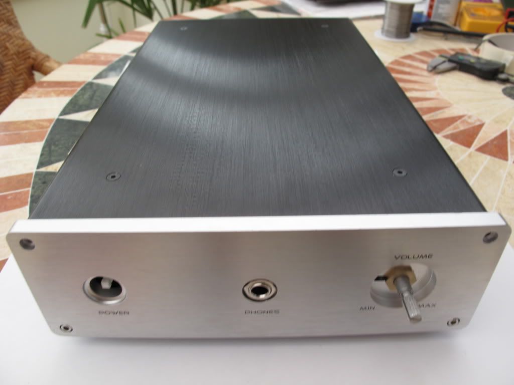 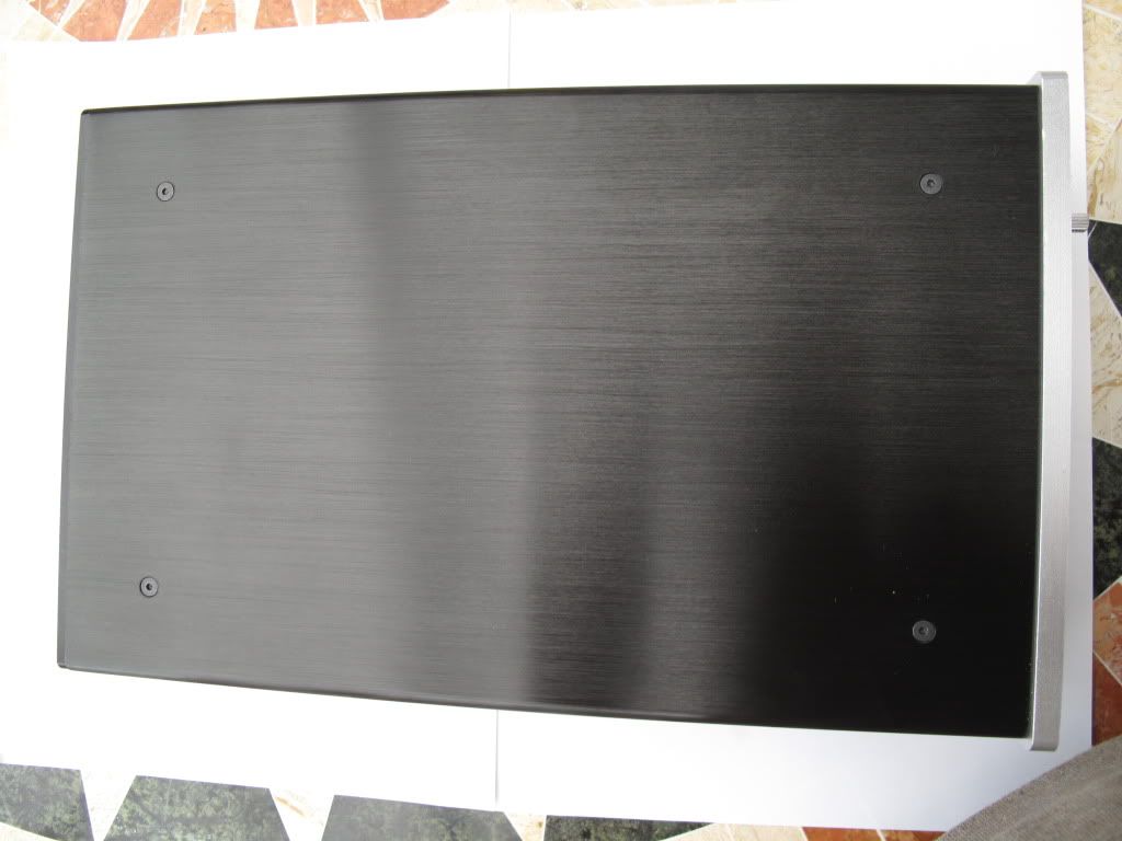 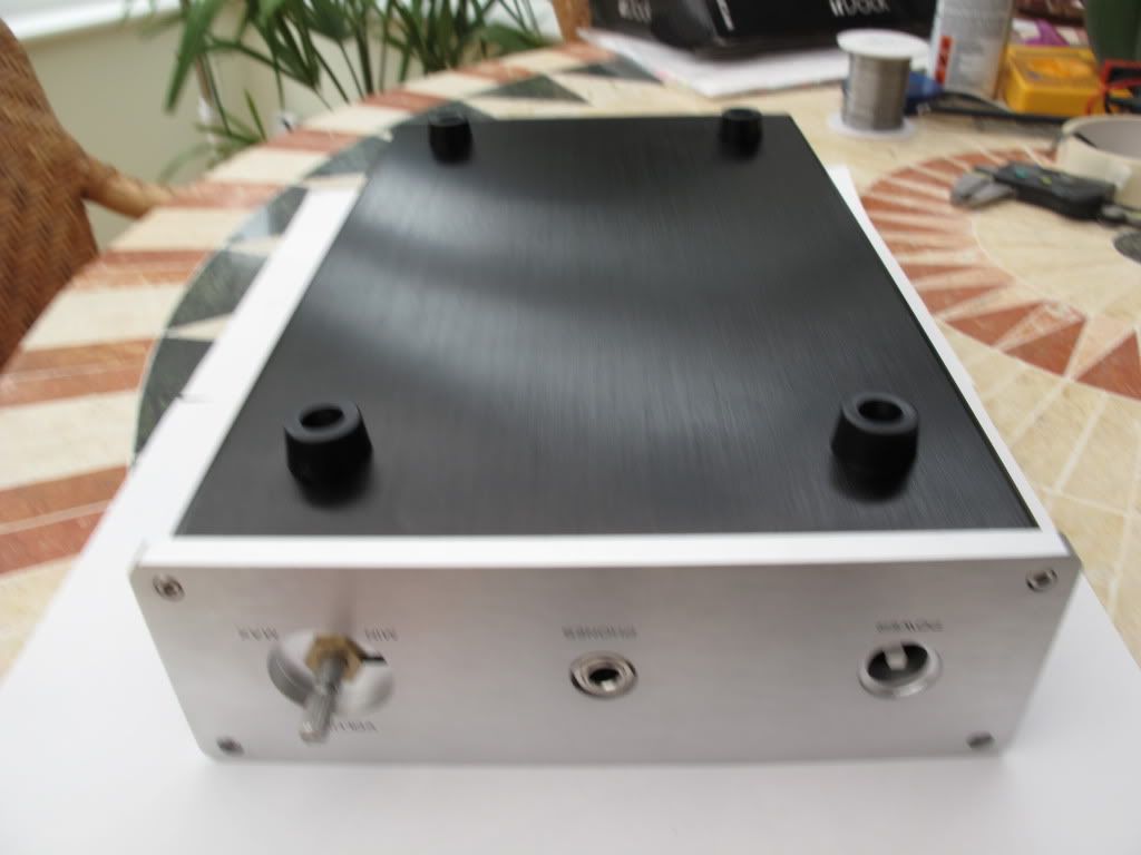 Mick. |
|
|
|
Post by mingo on Oct 17, 2010 15:28:35 GMT
Could somebody please tell me what components are needed but not included when you buy the Pande kit in order to have a 100% finished Panda? (Denmark 230 volts)
Furthermore, where can I buy the missing items?
Thanks very much.
|
|
|
|
Post by clausdk on Oct 17, 2010 18:54:33 GMT
Could somebody please tell me what components are needed but not included when you buy the Pande kit in order to have a 100% finished Panda? (Denmark 230 volts) Furthermore, where can I buy the missing items? Thanks very much. You will need: A toroid 50VA 18 0 18. Two RCA sockets Headphone socket A 230 volts inlet (jeg har bare brugt en samlemuffe) Some (>1M )cable for the insides. A box You should be able to find all at rs and or Rapid, maybe EEelektronic (danishfirm) can help you.. |
|
|
|
Post by Koolind on Oct 17, 2010 19:30:31 GMT
Also, you should have 2 resistors for the output, even if it can do without. There is a discussion about this in the other thread if you havent seen it yet..
|
|
|
|
Post by PinkFloyd on Oct 17, 2010 19:36:07 GMT
Hi Mike, The components came today, thank you very much.  Excellent! These are optional Ian you can fit either or both.... both go across live and neutral. The round thing is a MOV (varistor) which will protect your amp against surges. The blue thang is a class X2 capacitor, basically helps to suppress noise on the AC (not essential). The two grey thingways are class Y2 capacitors (again optional) they are also AC filter caps and you fit one of them between live and earth and the other between neutral and earth. Yes I have also sent some heatshrink. Best way to fit the input / output leads is on the TOP of the PCB (this saves you farting about underneath the board) Best way to do it is to tin the in / out lead's wires with solder. You then flood a good bit of solder into the pads on the top of the board, make sure it floods into the hole.... you now have three pads with solder flooded into them. Now what to do is this (to each joint) heat the pad until the solder becomes liquid and then push the tinned wire into the hole (with the soldering tip still on the pad) keep the tip on the pad until the joint flows nicely. Looking good Mick! Remind me, am I supposed to be getting you the toroid? I don't know quite where I am this week with all these antibiotics in my system  |
|
|
|
Post by PinkFloyd on Oct 20, 2010 21:13:27 GMT
Could somebody please tell me what components are needed but not included when you buy the Pande kit in order to have a 100% finished Panda? (Denmark 230 volts) Furthermore, where can I buy the missing items? Thanks very much. You will need: A toroid 50VA 18 0 18. Two RCA sockets Headphone socket A 230 volts inlet (jeg har bare brugt en samlemuffe) Some (>1M )cable for the insides. A box You should be able to find all at rs and or Rapid, maybe EEelektronic (danishfirm) can help you.. You will also need a 1amp slow blow (Time lag) 20mm fuse, a 20mm chassis mount fuseholder, an on / off switch, solder, a knob and some heatshrink. |
|
|
|
Post by PinkFloyd on Oct 20, 2010 21:52:52 GMT
Setting the Panda up. Before firing your Panda up there are a couple of adjustments to be made. First thing to do is to get the voltage across the 1K5 resistors between 1.2V and 1.5V (1.3V is a good "inbetween" value so I go for that but anything between 1.2V and 1.5V will be fine). Measure across the resistors shown (there are two per channel):  To adjust the voltage you will have to trim the pots (VR4 and VR5) there is one per channel... this diagram should make this easier to understand: 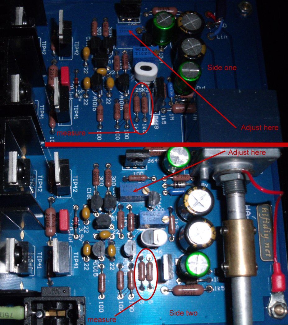 Slowly turn the screw on the top of the blue trimpots until the measurements across the 1K5 resistors on both channels are between 1.2V and 1.5V DC..... try to get channel one as close as channel two ie: 1.3V / 1.3V..... don't have channel one at 1.2V and channel two at 1.5V for example. Remember... you are measuring the voltage across both 1K5 resistors per channel (with the amp powered up) and your multimeter set to the DC voltage setting.... I will show this diagram again just so you are 100% sure of where you are probing:  Probe across BOTH 1K5 resistors PER channel. I think a few people have been only probing across both resistors on the one channel.... the "stock" Panda pictures may have been misleading and this an easy mistake to make  Hope this is crystal clear, if not then please let me know. I will deal with measuring the DC offset tommorow. Mike. |
|
|
|
Post by PinkFloyd on Oct 20, 2010 22:20:30 GMT
Next thing to do before listening to the fantastic music the Panda is about to caress your ears with is to adjust the DC offset. Same thing again.... we have a blue trimpot on each channel.... this time we are dealing with the blue trimpots which have "W201I" printed on the top of them.... these are 200R trimpots. (one per channel... ie: one for left / one for right) Follow these instructions: www.rock-grotto.co.uk/dcoffset.htm and trim the 200R pots (with a small screwdriver) until you get each channel below 10mV. You can also probe between left out and ground and right out and ground at the output on the PCB itself: 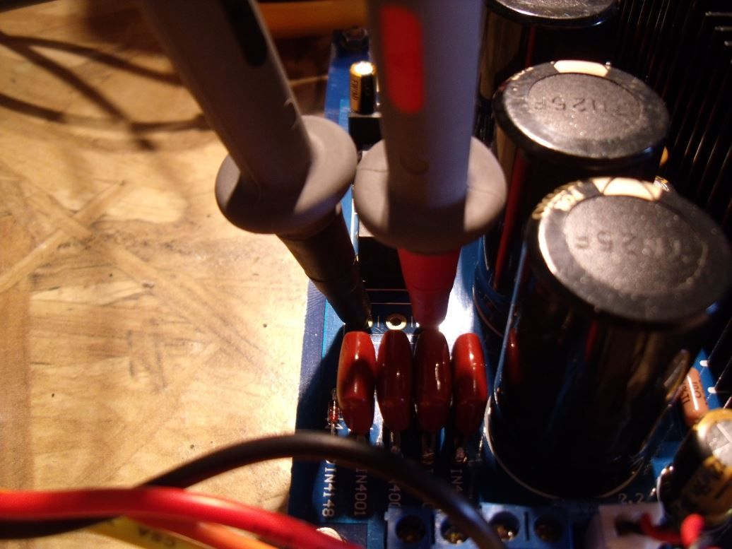 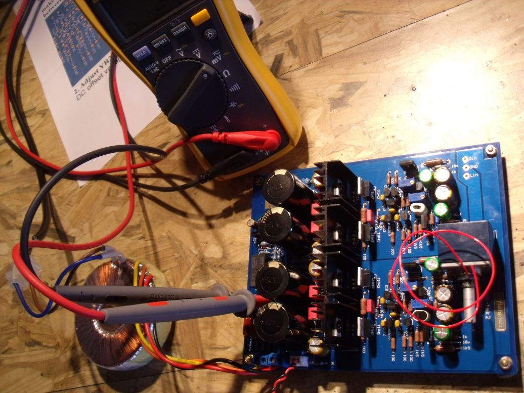 Either way, it's cool  just make sure you get BOTH channels below 10mV. I recommend you only measure / tweak the DC offset after the amp has been powered up for an hour or so and check it again after the first 100 hours of usage once everything has stabilised. Mike. |
|
Deleted
Deleted Member
Posts: 0
|
Post by Deleted on Nov 1, 2010 14:06:48 GMT
Adusting the gain: 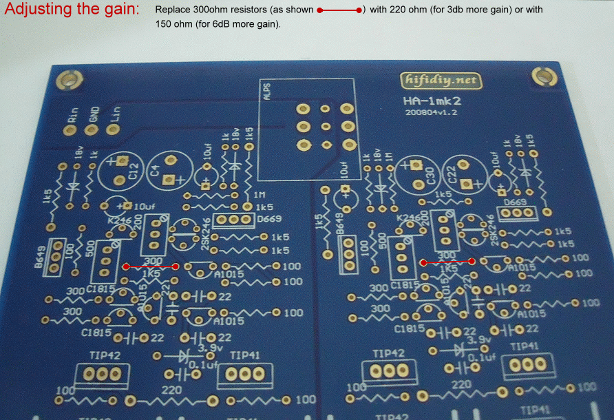 Thanks Frans. Mike, You say that achieving the 150 ohms can be done by attaching another 300 ohm resistor to to back of the PCB in the corresponding positions,to up the gain by 6db, in that case, what ohm resistor would be required to do the same to achieve a 3db increase in gain. Mick. |
|
|
|
Post by PinkFloyd on Nov 1, 2010 14:47:40 GMT
Hi Mick, Parallel a 1000 ohm resistor onto the 300 ohm resistor, that will give you 230 ohms which is pretty much +3db. This is a pretty handy calculator  www.1728.com/resistrs.htm www.1728.com/resistrs.htm |
|
Deleted
Deleted Member
Posts: 0
|
Post by Deleted on Nov 2, 2010 19:24:03 GMT
I changed the resistors to 130R today. While it was open I put 75R output resistors in place of the temporary 33R which was all I had.
All went well and I sat down for a listen which lasted about 30 seconds or so before silence. I had a think and went back through the setup adjustments that Mike and Frans gave instructions for. The previous DC offset figs, 0mv, were now negative - quite a bit! Readjusted and also set the 1.5k resistor figure up to 1.3v first.
Going beautifully now. There is an immense amount of detail from quite a low setting. I never heard the 701s sound anywhere near so well, superb. As Ian said, they now have bass.
Syd
|
|
|
|
Post by geetarman49 on Nov 3, 2010 18:22:24 GMT
Adusting the gain:  Thanks Frans. Mike ... how about a hack to provide front/back panel adjustable gain via a 3 pos. switch? this should be a better way to accommodate various hp's, no? without adjustable gain, i'm leaning towards the lovely cube kit which isn't that much different in price once all the bits and pieces are factored in (i'm in canada so your kit price can't come into play, unfortunately). & speaking of lovely (m-stage, lehmann), how does the panda stack up against it (them)? more than a passing similarity? tia, don |
|
Deleted
Deleted Member
Posts: 0
|
Post by Deleted on Nov 5, 2010 6:22:38 GMT
elongating the wires from the feedback resistor will (very likely) make the amp unstable as you would also introduce inductance (the wiring) and capacitance (the wiring running close together towards the switch) in a rather sensitive part of the amp.
The feedback point where these parts are located is crucial for HF and aidio feedback.
You could give it a try but recommend checking operation with a fast osciloscope and squarewaves afterwards to see if the amp has become unstable or oscillate.
If you like to have 'gain settings' consider setting the amp to the maximum desired gain and use a (switche-able) resistor devider network before the vol pot to adjust the input voltage.
Realise that when the gain is adjusted the DC output offset (being a DC coupled amplifier) also has higher DC offset and must be checked.
The output DC voltage will also vary more when warming up.
I would not recommend using more then 6dB gain for this reason alone.
|
|
Deleted
Deleted Member
Posts: 0
|
Post by Deleted on Nov 5, 2010 19:26:18 GMT
Great, you tried it then Mick. For me it's given the K701 a more musically varied life. I can use it with a wider range of music than I felt comfortable with before. What gain did you end up with? Not sure what 100ohm would do. I feel it's spot on now with 6dB and the tracking is also still perfect down at the bottom end. Hi Ian, My own one is fitted with 68 ohm resistors as i listen to my Senn 250`s most of the time, but i have tried the 100 ohms that i am fitting to toads in mine also, and the 701`s sound really nice with those fitted (sound fine with the 68 ohm actually), but toad will be listening to his 701`s most of the time. I have raised the gain 3 decibels on both mine and toads. Frans has sent me some special caps that he has made to alleviate the dc input problem on mine and possibly toads as well, will fit those tomorrow, should make no difference in SQ as it only rolls off the inaudible lows. Just waiting on bits i have ordered from Mike to arrive, then i can complete the build on other Ians, the PCB is working fine, just need the toroid and the screened wire really everything else is installed in the enclosure, except perhaps the need to fit dc eliminating caps also. Be nice to get his feedback on this Amp, as he swears by his 701`s, he should certainly notice a big improvement in SQ. Value for money does not come much better than on this Panda IMHO. Mick. |
|
|
|
Post by PinkFloyd on Nov 5, 2010 21:05:46 GMT
I've knocked up a tester for the 2SK246 transistors and it works very well... I will provide some photos once I tidy it up a bit. Basically it's a fixed voltage 1 amp (DC) power supply, a DIP8 socket (only using 3 of the sockets) and a multimeter set to the mA range. You can also use a 12V battery. I connect the input lead of the multimeter directly to the PSU (+) and the COM lead of the multimeter directly (soldered on) to two of the sockets on the DIL (which are linked together) I then run a lead from the negative terminal of the PSU to the third pin. It's then a simple case of powering up the PSU, turning the multimeter on (set at the mA range) and inserting the 2SK246. I tried ten 2SK246 from a production reel and here are the measurements I got: 1.51 mA 2.30 mA 3.10 mA 1.27 mA 1.62 mA 2.97 mA 1.72 mA 1.58 mA 2.11 mA 2.34 mA Pretty much all over the bastard joint  These transistors (the Toshiba ones) are not as close as the ones supplied with the kit and I'm possibly going to have to test the entire 100 just to get a few that are a "perfect" match. Question for frans...... "how" close is "close"? We are, obviously, not going to get 6 that match identically unless we spend hours going through quite a large batch.... I am quite content with them being, say, 2.10mA, 2.27mA, 2.30mA, 2.07mA, 2.60mA, 2.49mA etc. etc. I am not looking for 6 that measure "identically" or am I? If so, this exercise will cost more than the fekkin' kit itself  |
|
leo
Been here a while!  Team wtf is it?
Posts: 3,638
|
Post by leo on Nov 5, 2010 21:43:36 GMT
I'd have thought only the input pairs need matching (from the schematic Q6 matched to Q8 , Q15 matched to Q16) the other one each channel has a trimmer for adjusting the current .
You'll get some variation anyway when testing, temp makes em drift.
|
|
|
|
Post by PinkFloyd on Nov 5, 2010 21:51:07 GMT
By the way guys..... I've been speaking to the designer of the Panda and the headphones used by the "test team" were as follows: AKG K-501 AKG K-601 AKG K-1000 Sennheiser HD-580 / 600 Grado RS1 Beyer DT-931 The conclusions were that the Panda drives them all very well.... I'd imagine, with a few simple adjustments, that the Panda would be excellent with the K-1000  |
|
|
|
Post by clausdk on Nov 5, 2010 22:15:17 GMT
The conclusions were that the Panda drives them all very well.... I'd imagine, with a few simple adjustments, that the Panda would be excellent with the K-1000  I tried a pair of K 1000 with my Panda last weekend it was OK but lacked a bit in the power department.. |
|
Deleted
Deleted Member
Posts: 0
|
Post by Deleted on Nov 5, 2010 22:19:40 GMT
Question for frans...... "how" close is "close"? We are, obviously, not going to get 6 that match identically unless we spend hours going through quite a large batch.... I am quite content with them being, say, 2.10mA, 2.27mA, 2.30mA, 2.07mA, 2.60mA, 2.49mA etc. etc. I am not looking for 6 that measure "identically" or am I? I I'd say +/- 5 % is already pretty close for these FET's. It will be close enough to provide low DC offset drift over time/temp. So a 2.3mA could be matched with everything between 2.18 to 2.42. the absolute values do not matter but only the percentage of deviation between the 2. so a 1.58mA could be used with anything between 1.50 and 1.66. I would try to find 4 that match the most so the left and right channel are not miles apart in gain in the input stage. and put the ones closest together in one channel. How this translates sonically I don't know but it will help in DC offset drift. |
|
|
|
Post by PinkFloyd on Nov 5, 2010 22:23:13 GMT
Alex, My funky little tester does it all.... was just trying to make it simple to do for people who only have a multimeter..... even a PP9 battery (9 volt) battery and a multimeter is all that's required for a basic indication. We are not expecting first time builders to have a £3,000 oscilloscope to hand are we?  £40 for the kit, £3,000 for the test equipment.... erm, nope.... let's keep it real and "doable" for the vast majority of builders who are armed with nothing more than a humble multimeter  |
|
|
|
Post by PinkFloyd on Nov 5, 2010 23:11:07 GMT
First tester I knocked up was on a scrap bit of vero, cut up DIL socket and a PP9 battery lead/socket with leads at the other end to plug into the DMM. Obviously not the best way but only cost pence "pence" is what this place is all about..... maximum SQ for pennies  Yes, the PP9 is the way to go..... a nice stable voltage but once it starts running out of juice things change  By FAR the best transistor tweaker (for the beginner) is the PP9 battery and multimeter..... probably as accurate as the £3,000 "scope"  |
|
Deleted
Deleted Member
Posts: 0
|
Post by Deleted on Nov 6, 2010 14:08:13 GMT
Here are some photo`s of the dc input caps Frans kindly made for me installed in my Panda. I can now use either my cd player or iPod as the source, both sound great with these fitted, as i can not detect any degradation in SQ after fitting these. They consist of 2x......2 WIMA polyprops in parallel making them 4.4uf/100v. Mick. 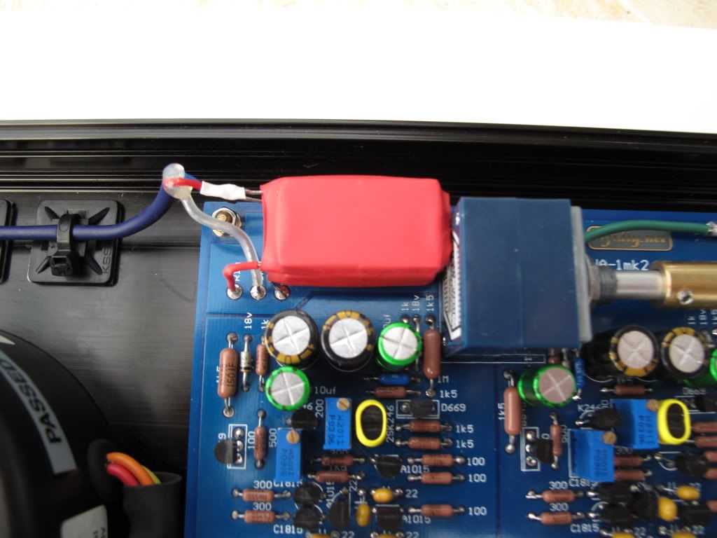 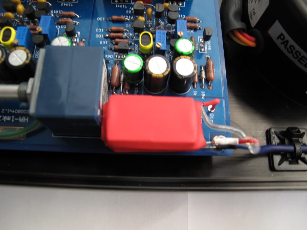 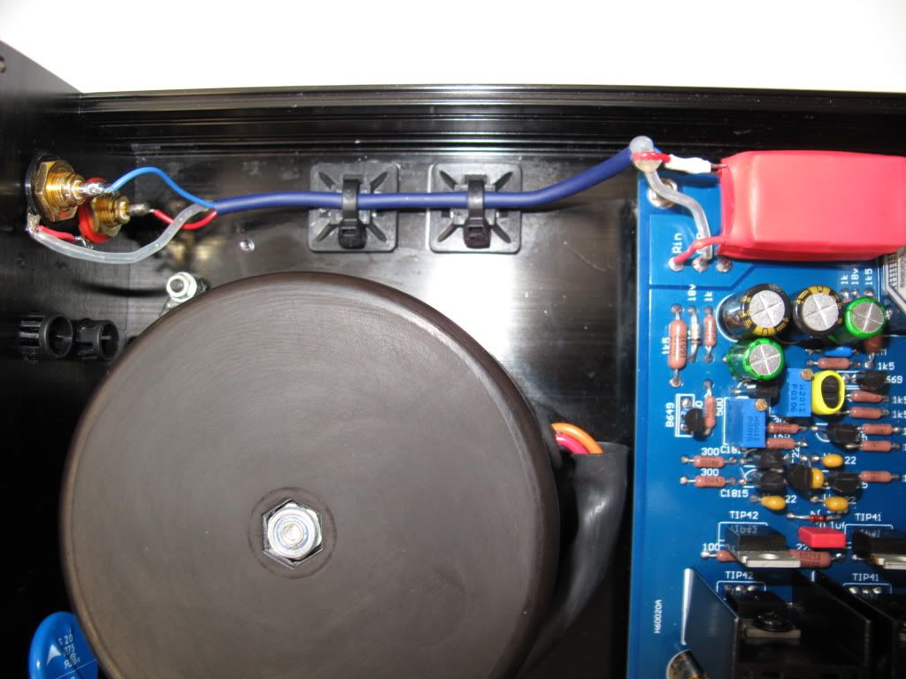 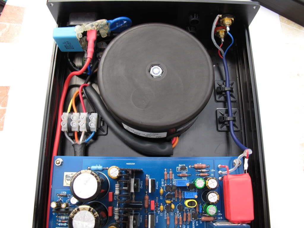 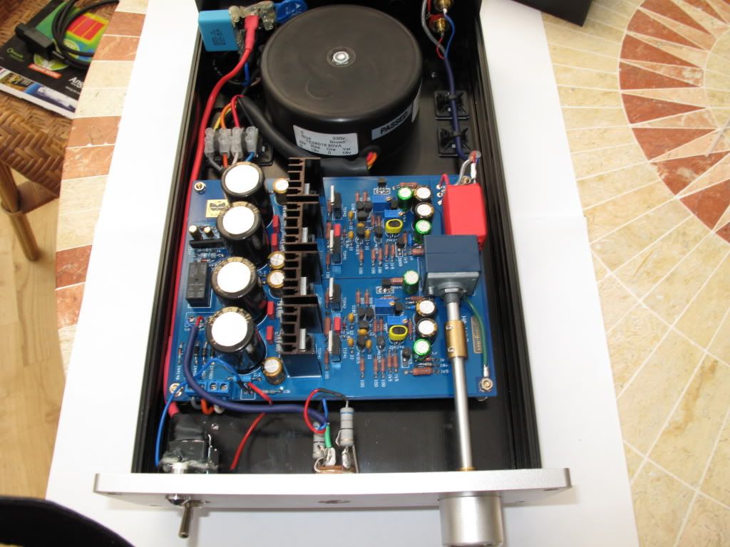 |
|
|
|
Post by PinkFloyd on Nov 6, 2010 15:37:35 GMT
|
|
|
|
Post by PinkFloyd on Nov 6, 2010 20:03:20 GMT
WOW! As per Fran's suggestion I have increased the voltage (501 trimpot) from 1.3V to 1.5V and there is even MORE grunt now! A definite improvement IMO  Turn both trimpots anti clockwise if you want to increase the voltage across the 1K5 resistors and recalibrate the offset when you have done this. I think you will agree, this definitely gives the Panda even bigger balls  |
|