Deleted
Deleted Member
Posts: 0
|
Post by Deleted on Oct 10, 2010 16:42:11 GMT
;D ;D ;D ;D
Brilliant!!
|
|
Deleted
Deleted Member
Posts: 0
|
Post by Deleted on Oct 10, 2010 17:57:23 GMT
I have my PCB assembled all went ok apart from a leg broke off one of the resistors with the coloured rings round them, it goes immediately in front of that rectangular black box and next to that small diode on the Panda logo edge of the PCB and is marked 5K on board. Has anybody got one i can have, or can tell me where to get one from.
Thanks.
Mick.
|
|
|
|
Post by PinkFloyd on Oct 10, 2010 18:16:00 GMT
I have my PCB assembled all went ok apart from a leg broke off one of the resistors with the coloured rings round them, it goes immediately in front of that rectangular black box and next to that small diode on the Panda logo edge of the PCB and is marked 5K on board. Has anybody got one i can have, or can tell me where to get one from. Thanks. Mick. I'll get one over to you on Tuesday Mick, no probs. Mike. |
|
Deleted
Deleted Member
Posts: 0
|
Post by Deleted on Oct 10, 2010 18:46:50 GMT
I have my PCB assembled all went ok apart from a leg broke off one of the resistors with the coloured rings round them, it goes immediately in front of that rectangular black box and next to that small diode on the Panda logo edge of the PCB and is marked 5K on board. Has anybody got one i can have, or can tell me where to get one from. Thanks. Mick. I'll get one over to you on Tuesday Mick, no probs. Mike. Cheers Mike, Its a pain in the backside trying to unsolder and move a component, in this type of PCB, or is it just me, that`s how i broke the leg off that resistor, i think i have the 100k and the 1k mixed up as well, my meter struggles to give a readable reading on these, have to be more careful removing and interchanging those  |
|
|
|
Post by PinkFloyd on Oct 10, 2010 19:29:38 GMT
I'll get one over to you on Tuesday Mick, no probs. Mike. Cheers Mike, Its a pain in the backside trying to unsolder and move a component, in this type of PCB, or is it just me, that`s how i broke the leg off that resistor, i think i have the 100k and the 1k mixed up as well, my meter struggles to give a readable reading on these, have to be more careful removing and interchanging those I'll send you 1k and 100K too  |
|
|
|
Post by PinkFloyd on Oct 10, 2010 19:53:23 GMT
Come on Mike ........... Is the lid on? Is the DC off set correct? Is it sounding the same as yesterday? Does it work? I've installed the fan, the triple glazing and the plastic 'sealing' sheets over doors. Thunderbirds are go.....  Lid not on yet, will get her packed up and ready to go tomorrow. Has been on 24/7 for 3 days now, there was slight fluctuation in the offset the first 24 hours but the last 24 hours it has remained stable @ 0.00mV (or as close as damn it) so I am happy that it is "good to go". Please also remember that it will take a good few hundred hours before giving it's "absolute" best... it will sound great straight out of the box but will get slightly "riper" with time. After firing her up allow 30 minutes or so for everything to heat up... it does sound better after warming up. No problems at all leaving this amp switched on 24/7/365 so, if you are one of these people who never switch their gear off then it's perfectly good to keep the Panda constantly powered up OR switch it off after listening to it. Some people argue that an amp will sound better in an "always on" state (Graham Slee being one of them).... his Solo, for example, takes an eternity to come on song which is why he recommends leaving it powered up. Do you have a set of hex / allen keys Ian? I want you to have a look under the bonnet as the pics only give you a 2D idea of what's going down.... have a look under the hood, get to know what does what.... you feed the bamboo shoots in through the headphone socket, it is pretty efficient and should only require 2 or 3 fresh bamboo shoots per day. You only have to unscrew the top two screws on the front and the top two screws on the rear.... you then lift the lid off. Warning, there are no edible parts inside so don't try to eat anything, also make sure the amp is unplugged from the mains before going in. Along with the amp I am including the 38ohm adaptor (which converts the output impedance to 120 ohm) and the parts list / schematic diagram. If I have time tomorrow I will make you up a nice mains lead to go with it. All the best, Mike. |
|
Deleted
Deleted Member
Posts: 0
|
Post by Deleted on Oct 10, 2010 20:19:08 GMT
I do Mike. I was thinking of taking one of those back 'blanks' out to allow people to see what the butler saw .... there's a pile of fools gold behind it.  |
|
|
|
Post by PinkFloyd on Oct 10, 2010 21:01:03 GMT
I do Mike. I was thinking of taking one of those back 'blanks' out to allow people to see what the butler saw .... there's a pile of fools gold behind it. Ah yes.... like a "peep hole" or one of those public toilets with a "glory hole"    What CDP will you be feeding her with? I have tried a buffer inbetween my CDP and the Panda and it is quite nice, definitely enhances the scale and granduer.... it will be interesting to hear what you think of it buffered V unbuffered. I'm sitting here listening to it right now and, again, have Touch yello playing away (at the 12 o' clock position on the volco) and it's really energetic and bouncy sounding.... very "polypropylene" in tonality, nice and rubbery, certainly not pedestrian and papery sounding. Ian..... I don't have any to hand at the moment BUT I can also fit a 3.5mm jack socket so you can use your ipod as source... this is VERY easy to do  |
|
Deleted
Deleted Member
Posts: 0
|
Post by Deleted on Oct 10, 2010 21:26:10 GMT
Source will be a Naim CD5i. When I can be bothered I hook the Ipod in via the bottom end, but it can be a bit lethal as far as sound goes, so I often use a portable setup in my armchair. A portable amp with Portapro or ES7. It's not as revealing then so MP3 is bearable.
I wonder whether Apple have got a monopoly on those stupid leads. Ferkin' difficult to solder and all that's available on general market are those awful one strand pieces of copper that wrap themselves up on a wheel arrangement or the Ipod version with an av plug as well.
I paid some guy in America stoooopid money for a dock cable which he wired backwards!!! As Alex said to you about the amp, turn the headphones round and it's fine. Then I found one for £6 I think it was. It's OK. To go into the amp I connect via a barrel into another lead with phonos. It's only mp3 after all!!
Other than that, you pay stupid money for an 8 inch (if you're lucky) piece of wire with 3 plugs that barely bends!!
I tend to use the posh amp for CD's with occasional Mp3 use or wav/lossless which is better.
|
|
|
|
Post by PinkFloyd on Oct 10, 2010 21:54:32 GMT
|
|
|
|
Post by PinkFloyd on Oct 10, 2010 22:56:31 GMT
|
|
Deleted
Deleted Member
Posts: 0
|
Post by Deleted on Oct 11, 2010 6:40:45 GMT
FAME! We're gonna live forever ..... remember, remember, RG member ...... FAME |
|
|
|
Post by Koolind on Oct 11, 2010 9:58:54 GMT
How many volts is the LED-output ? 12v?
|
|
Deleted
Deleted Member
Posts: 0
|
Post by Deleted on Oct 11, 2010 11:10:04 GMT
a LED is driven by a current, not a voltage.
There are LED's (indicator LED's) for use in cars that have internal resistors so they work fine on 12V.
The LED in this case may be any color you like and the voltage across it is not of importance and will vary from color to color.
The resistor that belongs with it is already mounted on the PCB right next to it.
The only thing you have to worry about is the polarity.
Connect it the wrong way around and it won't light up.
The voltages are not spectacularly high so mounting it the wrong way around doesn't need to result in failing of the LED.
Should you find the LED too bright (or too dim) you can change this by altering the value of the resistor connected to it.
be carefull with this, too low resistance values may destroy the LED.
|
|
|
|
Post by Koolind on Oct 11, 2010 12:26:42 GMT
Solderdude - Thanks.. I thought that LED's were pretty sensitive in that area.. As for the much talked about output resistors; Which type would be the best fit for the panda? And how many watts should they withstand? I saw that Mike was using a couple of 5w wirewound(i think?) ones. Is this sort of overkill, or does it serve a purpose using this large resistors? Apparently i dont know as much about electronics as i hoped  I am willing to learn though; This project will hopefully be both fun and educational for me. |
|
|
|
Post by PinkFloyd on Oct 11, 2010 12:37:59 GMT
Solderdude - Thanks.. I thought that LED's were pretty sensitive in that area.. As for the much talked about output resistors; Which type would be the best fit for the panda? And how many watts should they withstand? I saw that Mike was using a couple of 5w wirewound(i think?) ones. Is this sort of overkill, or does it serve a purpose using this large resistors? Apparently i dont know as much about electronics as i hoped I am willing to learn though; This project will hopefully be both fun and educational for me. 0.5 watt will do.... the ones I have used are not wirewound, they are Kiwame carbon film types. Full description as follows: "These are an excellent match for Hi-End Audio. Kiwame resistors are from Japan and characterized by lower noise than metal film resistors and a more natural sound. There is a growing enthusiasm for these carbon film resistors because they recapture the vintage tube sound without the drift of carbon comps. They are also very compact given their wattage rating. The resistance material is carbon film with coated silicon and finished in green. Since their first introduction in the audio industry they have managed to gain reputation and the respect of both manufacturers and worldwide diy-ers. In fact several manufacturers openly suggest Kiwame resistors along with the 'usual suspects' (quality capacitors etc.) for the upgrade of their products. Lately Kiwame resistors found another audio application, that of the step ladder attenuators used as volume potentiometers. Browsing internet audio forums and DIY discussion groups proves that Kiwame resistors really make a difference! Kiwame resistors are made of carbon film and their case is actually the first one for use is audio applications with superior specifications! Considerably low thermal noise levels, lower than metal film resistors! Lower distortion artifacts On the other hand they offer true 0.5% tolerance despite their nominal E24-series 5% label ! If you don't believe it a multimeter will certainly convince you. Their sonic character can be briefly described as follows : Effortless reproduction ('non fatique') subjectively perceived as an increase of headroom. Extensive neutrality. " |
|
|
|
Post by Koolind on Oct 11, 2010 12:52:38 GMT
Does the 5 watts give an advantage compared to 0.5 watt then?
And would you rather use a 0.5watt carbon film than ie. a 2watt metal film, 3watt wirewound or 3 watt metal oxide.
Its hard to make a qualified choice when the specifications are rather similar, but the construction ant material type is very different.
To a novice mind more watts and size seems appealing and "better" but i suspect that isnt the case here?
|
|
|
|
Post by dicky on Oct 11, 2010 13:32:10 GMT
Hi folks, this is my 'cherry' post - so please be gentle with me!  I've been lurking here for a while and must say you guys seem to be a great bunch and very knowledgable. I expect to pick up some great tips and get some education here and I've already learned alot (and spent a fortune :  - being a newbie to headfi. Anyhow, I've been following the Panda thread and have bought one - but I've been holding off building it until Mike has built Panda 3 - just so I don't damage any components or the board if any components need changing. So, in relation to changing components, if these Kiwame resistors are so good for audio use, why wouldn't one simply replace all the Panda resistors with like-for-like Kiwame equivalents? Would this be an even better sounding 'super-Panda'? I hope this isn't a blindingly stupid question!? |
|
Deleted
Deleted Member
Posts: 0
|
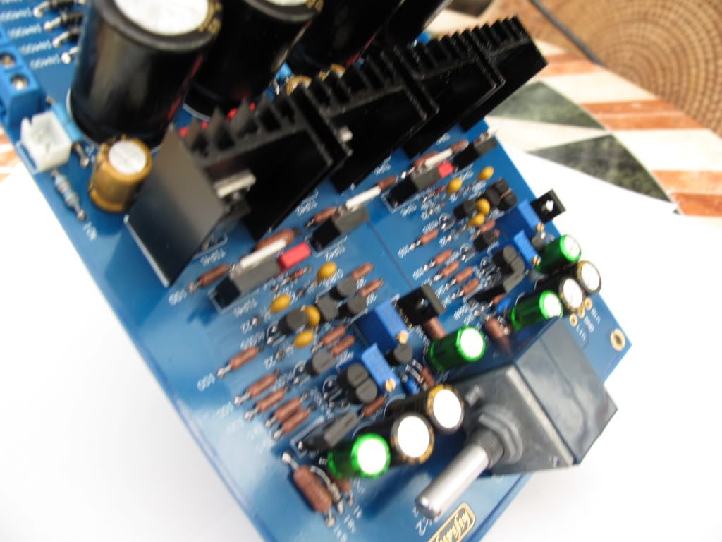
Post by Deleted on Oct 11, 2010 13:36:43 GMT
|
|
|
|
Post by Koolind on Oct 11, 2010 13:46:59 GMT
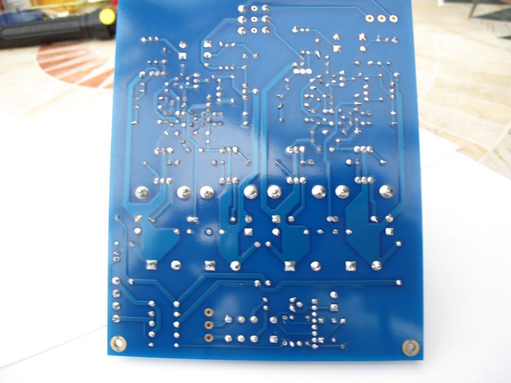
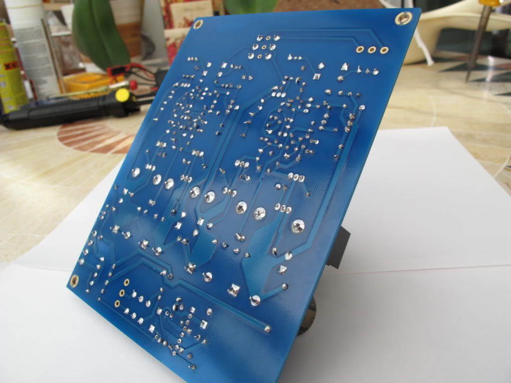
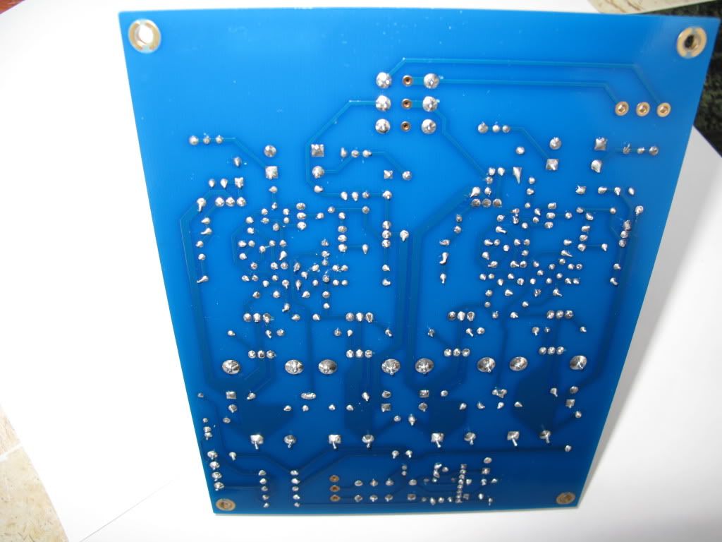
Heliharris - Nice job ! The soldering looks pretty good to me. I hope that i can manage to make my PCB as nice also I suspect that you have spent quite a bit of time on fitting the components nicely with the writing up and the same distance to the bends etc.. Very nice looking indeed! |
|
Deleted
Deleted Member
Posts: 0
|
Post by Deleted on Oct 11, 2010 14:16:04 GMT
Thanks Koolind, Yes took me all day yesterday to solder all the components( already had the resistors mounted but not soldered) . I am not an electrician and this is my first go at something "major" well to me anyway. The only thing, or "tip", ( if i may be as bold to say) i can pass on is to make sure that the components are the right ones and in there right place BEFORE soldering as two hrs was spent trying to remove three resistors and installing two where they should have been, very difficult in these through hole boards, i found. Mick. |
|
|
|
Post by PinkFloyd on Oct 11, 2010 14:25:26 GMT
Thanks Koolind, Yes took me all day yesterday to solder all the components( already had the resistors mounted but not soldered) . I am not an electrician and this is my first go at something "major" well to me anyway. The only thing, or "tip", ( if i may be as bold to say) i can pass on is to make sure that the components are the right ones and in there right place BEFORE soldering as two hrs was spent trying to remove three resistors and installing two where they should have been, very difficult in these through hole boards, i found. Mick. Just snip them off and solder new ones direct onto the pad on top of the board OR.... "form" the legs of the new resistor, heat the pad and push the leg of the new resistor in... this will force out the old leg OR.... heat the pad and pull out the old resistor with a pair of long nose pliers.... heat the pad again and when melted suck out the solder with a desoldering gun. |
|
Deleted
Deleted Member
Posts: 0
|
Post by Deleted on Oct 11, 2010 14:47:55 GMT
Yes that`s ok if you have replacements at hand Mike, but i had to re-use the old ones, so had to get them out in one piece, so i could resolder them in there correct position. Never mind i am pleased with my efforts anyway. Mick. |
|
Deleted
Deleted Member
Posts: 0
|
Post by Deleted on Oct 11, 2010 15:01:11 GMT
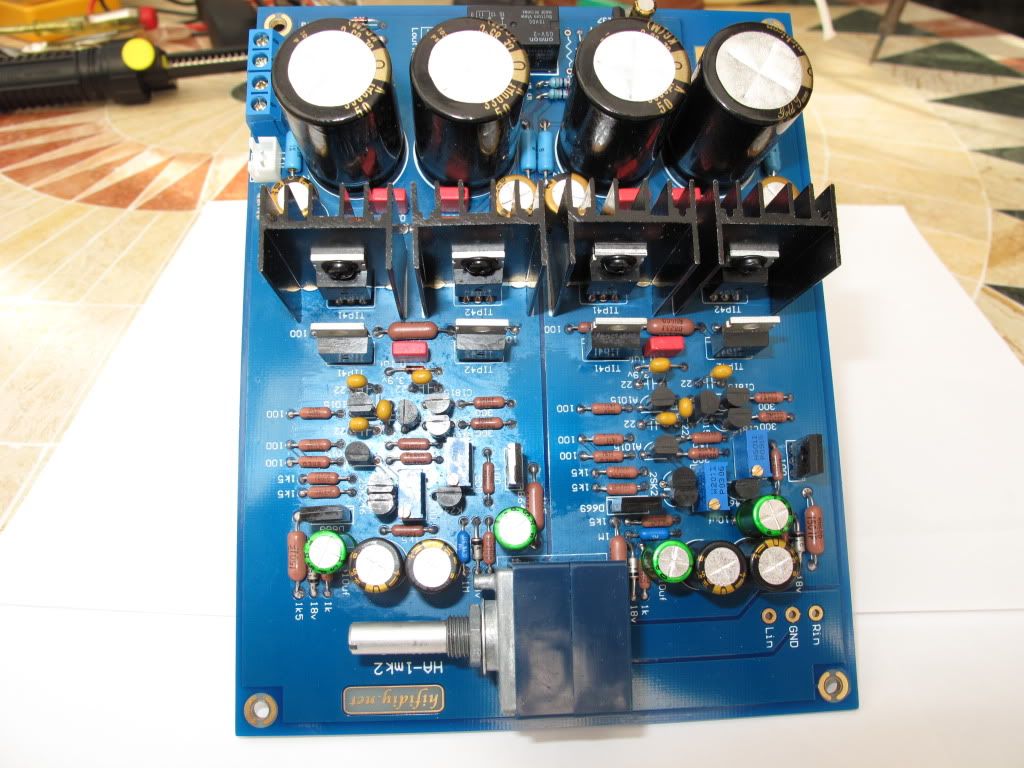
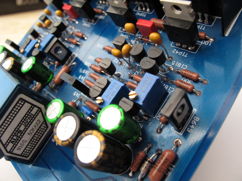
I noticed you mounted the ceramic caps rather high.
I would advice to mount them as close as possible to the board.
No need to mount them lower as they have been soldered already.
These ceramic capacitors have a tendency to break if you try to resolder them or reposition them when reheated.
For the smae reason: when mounting them don't 'force' them in the last bit.
Further the build seems fine... job well done
|
|
Deleted
Deleted Member
Posts: 0
|
Post by Deleted on Oct 11, 2010 15:12:05 GMT
Does the 5 watts give an advantage compared to 0.5 watt then? And would you rather use a 0.5watt carbon film than ie. a 2watt metal film, 3watt wirewound or 3 watt metal oxide. Its hard to make a qualified choice when the specifications are rather similar, but the construction ant material type is very different. To a novice mind more watts and size seems appealing and "better" but i suspect that isnt the case here? My answer would be: I would prefer 0.5W metal film or carbon composite or carbon film over wirewound as wirewound acts more like a coil (unless we are talking about special wound, so called bifilar winding, wirewound resistors) then the film or composite types. When you were to short the output of the amp and have a 68 Ohm resistor mounted and it would be putting out a continuous sinewave at maximum power the resistor would be dissipating 1.4 Watts. In practice with musical content and a headphone connected the dissipated power would always remain well below 0.5W. Your ears would be glowing before the resistors are with this power. With smaller resistor values of say 10 Ohms (recommend to experiment with those values as the Panda is quite capable of handling this) the recommended rating would be a 5W type for this one. There are ceramic power resistors that can handle these power and have almost zero induction, just like carbon composite. Shorting the output in this vcase and playing it full power will burn out the 10 Ohm emitter resistors in the output stage and possibly overheat the power transistors. Keep in mind that when fitted you can literally destroy low ohmic headphones with it, not high Ohmic (above 300 Ohm) though. |
|


 I am willing to learn though; This project will hopefully be both fun and educational for me.
 I've been lurking here for a while and must say you guys seem to be a great bunch and very knowledgable. I expect to pick up some great tips and get some education here and I've already learned alot (and spent a fortune :
 - being a newbie to headfi.