|
|
Post by clausdk on Aug 28, 2010 9:22:37 GMT
And a new car wouldn't be bad either. . . . . .
|
|
|
|
Post by PinkFloyd on Aug 28, 2010 9:42:38 GMT
Claus, I didn't use any of my 1N4001 so will send you all four of them.... anything else you need whilst I'm at it? Well come to think about it I will be needing a HPsocket and RCAsockets.. Anything else?  |
|
Will
Been here a while!  Ribena abuser!
Member since 2008
Posts: 2,164
|
Post by Will on Aug 28, 2010 9:44:37 GMT
Aaargh! This looks very interesting, and very good value! I'm getting very itchy fingers here. The only way to stop myself buying one is to look at the (growing) pile of incomplete projects I have on the go! The seller also had some Pass-inspired  amp kits a few weeks back, that also looked good value, any if what you guys have received is anything to go by, good quality as well. |
|
Deleted
Deleted Member
Posts: 0
|
Post by Deleted on Aug 28, 2010 11:54:09 GMT
Good idea Mike.
75 Ohms is a 'universal' value.
Some can's like 10 Ohms others 120 Ohms and others inbetween (sigh)
@ Claus
> What is strange to me, is that first we put in a component that makes sure that the current only flows one way, which is probably because the caps and other parts will be harmed by current in the wrong diretion ??
Capacitors will blow their hat off and transistors en other parts end up in smoke and all you'll hear is a very loud hum if the diodes weren't there (replaced by a piece of wire) and a transformer is connected.
> But putting the snuffercaps on top, gives the current a loophole, so if current is running the wrong way, would it not take the "capway" and make havoc ??
Only very high frequencies will travel though the caps as if they were not there, but as they are all connected together these currents run only through the caps) and are 'shorted'.
That's what they effectively do.
The lower the frequencies the higher the reactance (sort of a resistance but with a phase shift between voltage over it and current through it).
For 50Hz a 100nF is about 30kOhm to give you an idea.
> It seems like a oneway street, where convertibles are allowed to go in the wrong way.
More like a oneway street where cars go in one direction and tiny mosquitos may travel in both directions.
They won't influence the direction and speed of the cars.
|
|
|
|
Post by PinkFloyd on Aug 28, 2010 12:18:22 GMT
Claus, I didn't use any of my 1N4001 so will send you all four of them.... anything else you need whilst I'm at it? Well come to think about it I will be needing a HPsocket and RCAsockets.. OK, I've sorted you out a Neutrik head socket, some RCA chassis mount sockets, a 275V varistor, a class X2 EVOX suppression cap, 2 x class Y suppression cap, 4 x 1N4001 and a selection of output resistors (22R / 30R / 39R / 47R / 75R / 80R / 100R / 120R) this should keep you entertained  |
|
|
|
Post by PinkFloyd on Aug 28, 2010 12:23:35 GMT
Yup, it's hard to justify a "new project" when you see so many half built things piled up in a corner.... thing is, some of them you "want" to complete... others you put on the backburner for a rainy day... it pishes down every day here but I still don't manage to get round to them  This project, on the other hand, is quite a simple one (especially if you buy the matching / pre-drilled enclosure) just a case of slotting it all together and, hopefully, "Bob's your Uncle...." you will plug it in and listen to your favourite songs..... That's the theory anyway  |
|
Deleted
Deleted Member
Posts: 0
|
Post by Deleted on Aug 28, 2010 13:25:55 GMT
I will soon put paid to that theory Mike!!  ;D |
|
|
|
Post by clausdk on Aug 28, 2010 18:38:05 GMT
Well come to think about it I will be needing a HPsocket and RCAsockets.. OK, I've sorted you out a Neutrik head socket, some RCA chassis mount sockets, a 275V varistor, a class X2 EVOX suppression cap, 2 x class Y suppression cap, 4 x 1N4001 and a selection of output resistors (22R / 30R / 39R / 47R / 75R / 80R / 100R / 120R) this should keep you entertained  Thank you so much.. I am really looking forward to hear the finsihed thing.. |
|
|
|
Post by PinkFloyd on Aug 28, 2010 19:20:55 GMT
OK, I've sorted you out a Neutrik head socket, some RCA chassis mount sockets, a 275V varistor, a class X2 EVOX suppression cap, 2 x class Y suppression cap, 4 x 1N4001 and a selection of output resistors (22R / 30R / 39R / 47R / 75R / 80R / 100R / 120R) this should keep you entertained  Thank you so much.. I am really looking forward to hear the finsihed thing.. Claus, In the meantime it would be a good idea to double check everything and then double check it again. Do you have a photo of the underside of your board? Mike. |
|
|
|
Post by PinkFloyd on Aug 28, 2010 19:58:00 GMT
Frans,
You mentioned shielded cable from the pot pads on the board to the chassis mount pot.... is this really necessary? It will be a very short run, maybe around 4 inches.... surely silver plated copper PTFE would be fine for this short run? If push comes to shove I could shield the wires in aluminium tape and connect the tape to ground.
|
|
|
|
Post by clausdk on Aug 28, 2010 20:25:30 GMT
My wife took the camera when she left . . . . .
For a vacation, so no pictures in a couple of days..
|
|
|
|
Post by PinkFloyd on Aug 28, 2010 20:51:29 GMT
Actually Frans.... just had a dig about and found a couplier extension kit.... I knew I had one somewhwere  It's got a 350mm (6mm dia) rod, L shaped bracket, front panel mounting bush and two rectangular cutouts so looks like the pot WILL be board mounted after all  I don't remember where I got this extension kit from but will have a hunt around the net to see if I can find one that's the same..... cuts down on wiring AND places the pot closer to the source input.... it can only be good  |
|
Deleted
Deleted Member
Posts: 0
|
Post by Deleted on Aug 28, 2010 22:32:29 GMT
Was out all day and evening...
Volpot where it is now (on board) with extension rods is preferable over extension with wires.
Like you say it can only be good !
If I had to put the pot in the front (in case I did not have extension rods and it's easier to solder some wires on then make a good extension rod (Mick will think the other way around and make an extension rod before picking up the soldering iron I reckon) I would have used screened cable, even for short distances because even at 10k it can still pick up hum.
When using toroids and short wiring this may not be a problem, but personally I am focussed on, and hate, hiss and hum.
Simply because I know it can be avoided.
For those who don't have an extension rod they can use short pieces of unscreened wire and see if there is no hum.
If there isn't any hum and you have a (grounded) metal housing then you don't need screened wiring at all.
|
|
|
|
Post by PinkFloyd on Sept 2, 2010 20:32:18 GMT
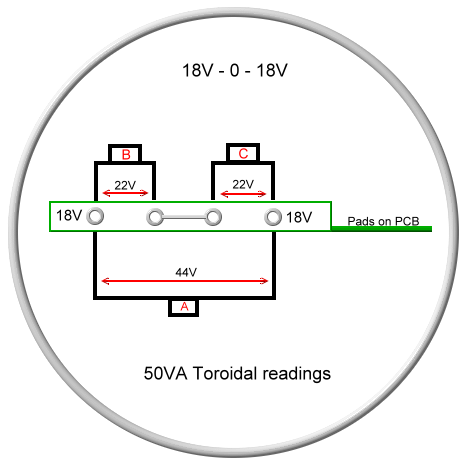
Postman was here today and told me I owed him £13.50.... I told him he had already got his tip at Christmas!  Anyways, turns out this "£13.50" was a duty charge on a package from abroad..... I scratched my head and couldn't think of anything I'm waiting for that would have 17.5% worth £13.50.... he then tells me that Royal mail impose an £8 handling charge! Eight quid?!! yet another prime example of this RIP OFF country we are living in. I said "ok then, bring the package in".... oh no, not as simple as that, you have to pay first then they deliver it the next day! What a scam! £8 to the Royal Mail and £5.30 to the customs. I don't mind the £5.30 but the £8? an absolute disgrace if you ask me. The postman is the nicest guy on the planet and really looks after me where mail is concerned but nothing he could do about this one  Sooooooo.... looks like the enclosure will be here tomorrow  The courier arrived an hour later with a box of 50 transformers and a few 18V "samples"  (50VA / 80VA/ 100VA ) Nice looking toroids, very smartly put together. I think that 50VA will be more than enough for this project and this is what I will start with. Connecting the thing up: This can be daunting if you have never set eyes on a toroid before but actually it's quite easy as I'm going to tell you how to do it for a 230V toroid. Primary side there is a brown and a blue wire.... blue goes to neutral and brown goes to live on your 230V mains supply. On the secondary side there are four wires.... Yellow, orange, red and black.... these are the wires that go to the amp's power input pads (18V in) it says 16V on the board but we are using 18V instead. I am NOT going to confuse you with technobabble, instead I will show you what wire goes where.... simples   Hopefully, if I've got this right the thing won't go up in a puff of smoke but I will confirm these connections when I make them tomorrow  That's all you need to know to connect the toroid. Let's take it slightly further though.... the connection on the board is centre tapped which means we are realising more in the region of 44 volts between the two outer wires (not 18V as you may think!) so when / if you measure between 18 / 18 and 18 / 0 you are likely to get these actual readings:  You may think "22V? that's awfully high!" don't worry, this will drop to 18V, or thereabouts, under load. Basically, all I am saying here is that you will NOT get a measurement of 18VAC even though the transformer says it is "18V".... expect 22V between B & C and 44V between across A. I really hope I have read that Chinese diagram correctly or I will be squirting a fire extinguisher on this thing tomorrow  Will keep you posted  |
|
Deleted
Deleted Member
Posts: 0
|
Post by Deleted on Sept 3, 2010 9:50:26 GMT
Still waiting for my PCB and components, enclosure is supposed to be on its way also, i expect to be stung for the tax as well then Mike, i have never paid tax on anything from Hong Kong before!! strange.
Mick.
|
|
Deleted
Deleted Member
Posts: 0
|
Post by Deleted on Sept 3, 2010 10:15:30 GMT
> I really hope I have read that Chinese diagram correctly or I will be squirting a fire extinguisher on this thing tomorrow This comical note triggered a serious reminder for those that care..  IF you have to use a fire extinguisher (hope you never need to) preferably DO NOT use a powder extinguisher. These are the cheap ABC fire thingies for in the home and car !  besides that it will give you the runs on the toilet after you scuirted one the salt particles will ruin every electrical part in the room (including the connections and wiring in wall sockets e.t.c)  If you intend to buy a fire extinguisher then go for a foam extinguisher instead.  Don't put electrical fires out with water for obvious (conducting of current mains) reasons b.t.w.  The powder things do put out a fire (if not too big and just starting) but ruin everything electric that is is the same room afterwards (not immediatly but after some time)  (have taken a course in firefighting and safety, that's where I stumbled onto this info) |
|
|
|
Post by clausdk on Sept 3, 2010 10:38:18 GMT
> I really hope I have read that Chinese diagram correctly or I will be squirting a fire extinguisher on this thing tomorrow This comical note triggered a serious reminder for those that care..  IF you have to use a fire extinguisher (hope you never need to) preferably DO NOT use a powder extinguisher. These are the cheap ABC fire thingies for in the home and car !  besides that it will give you the runs on the toilet after you scuirted one the salt particles will ruin every electrical part in the room (including the connections and wiring in wall sockets e.t.c)  If you intend to buy a fire extinguisher then go for a foam extinguisher instead.  Don't put electrical fires out with water for obvious (conducting of current mains) reasons b.t.w.  The powder things do put out a fire (if not too big and just starting) but ruin everything electric that is is the same room afterwards (not immediatly but after some time)  (have taken a course in firefighting and safety, that's where I stumbled onto this info) A blancet will do just fine throw it over when the fire starts, we are not talking forrest fires here.. If I should use "proffesionel gear" I would go for a CO2 thing no residue, no cleaning.. |
|
Deleted
Deleted Member
Posts: 0
|
Post by Deleted on Sept 3, 2010 11:41:53 GMT
a fire blanket that is...  As long as it can put out class B fires it'll do. Disadvantage of CO2(class B) over foam (class AB) is you can't use it to extinguish people on fire as the low temperatures also cause burnwounds, doesn't put out some class A fires neither.  For only electrical fires and B type fires CO2 is the better choice indeed.  The 'warning' was only for powder (Class ABCD) extinguishers as they ruin everything electrical. Try to claim your expensive equipment 6 months or so after a small fire was put out with one of those. |
|
|
|
Post by clausdk on Sept 3, 2010 11:44:03 GMT
|
|
Deleted
Deleted Member
Posts: 0
|
Post by Deleted on Sept 3, 2010 11:46:16 GMT
That must have been a lot of fun. ;D I used to blow fuses with a wallplug that was shorted inside to interrupt the lessons. Ofcoarse I got caught rather soon as it was obvious who would do such a thing.  the thread is drifting again.. Let's hope Mike 'fired it up' without setting any fires  and gives us an impression soon  |
|
|
|
Post by clausdk on Sept 3, 2010 12:14:35 GMT
Can I use the torrodial from my Andante with this amp ?? It is 15 volts. It is going to be pretty frustrating having an amp. standing ready and no way of using it   The powderthing was NOT funny afterwards  |
|
Deleted
Deleted Member
Posts: 0
|
Post by Deleted on Sept 3, 2010 14:42:59 GMT
That's probably true for a lot of practical jokes..  2 X 15V AC might just be enough. Also you must measure the AC voltage of the transformer before it is connected to the amp. Very likely it will measure 16V or maybe even 17V. It will need to have 2 windings (separate or CentreTap). If they are separate windings then check after having connected 1 wire from one winding to one wire of the seond winding if the voltage between the 2 still unconnected wires is double the voltage of a single winding. If it is, then you have connected it the right way. IF you measure between the 2 unconnected wires and get 0V, the transformer coils are connected in counterphase and you must unconnect the wire between winding 1 and 2 and connect the same wire from winding 1 to the other wire of winding 2. Then check if the total voltage is 2x the single voltage of 1 winding. If all is well connect the transformer to the amp and measure the DC voltage on the big capacitors. If it is above 20V (and below 30V) you can use this 15V transformer without much problems. |
|
|
|
Post by PinkFloyd on Sept 3, 2010 20:02:59 GMT
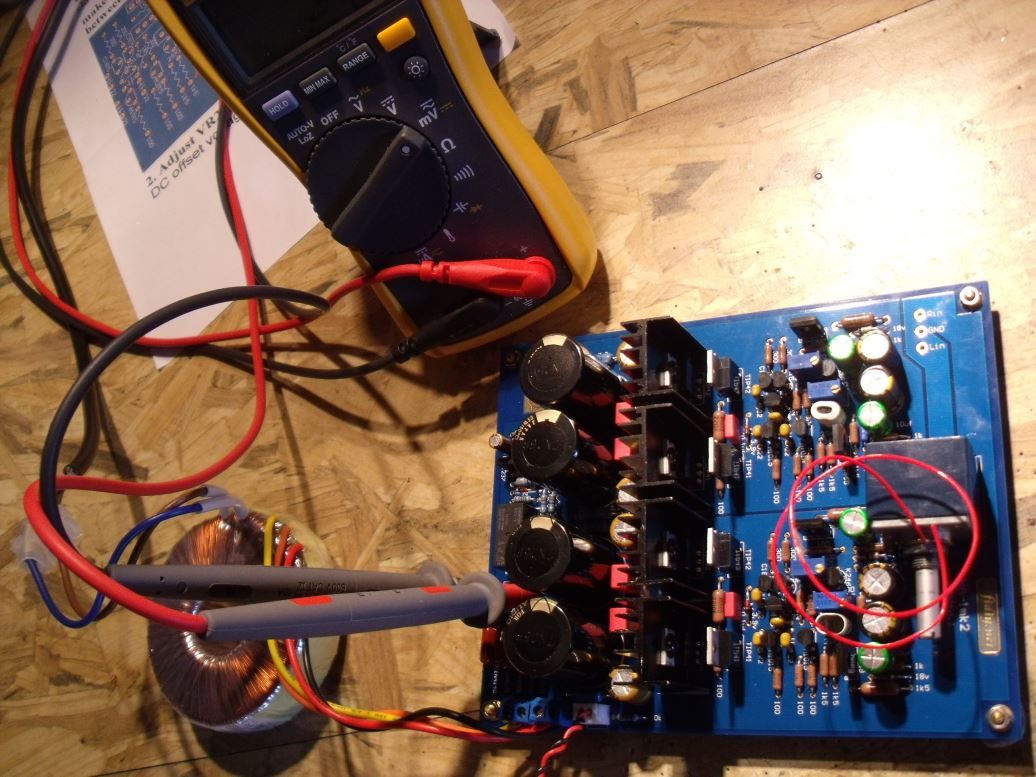
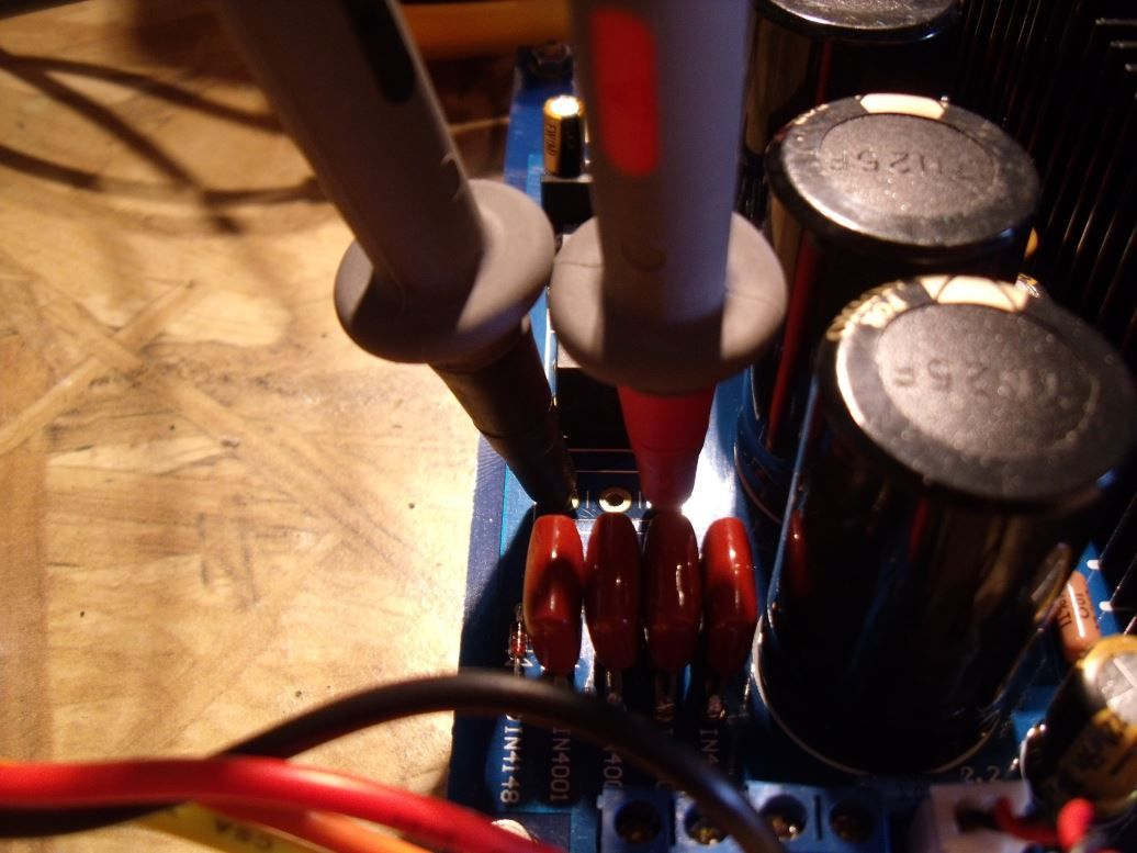
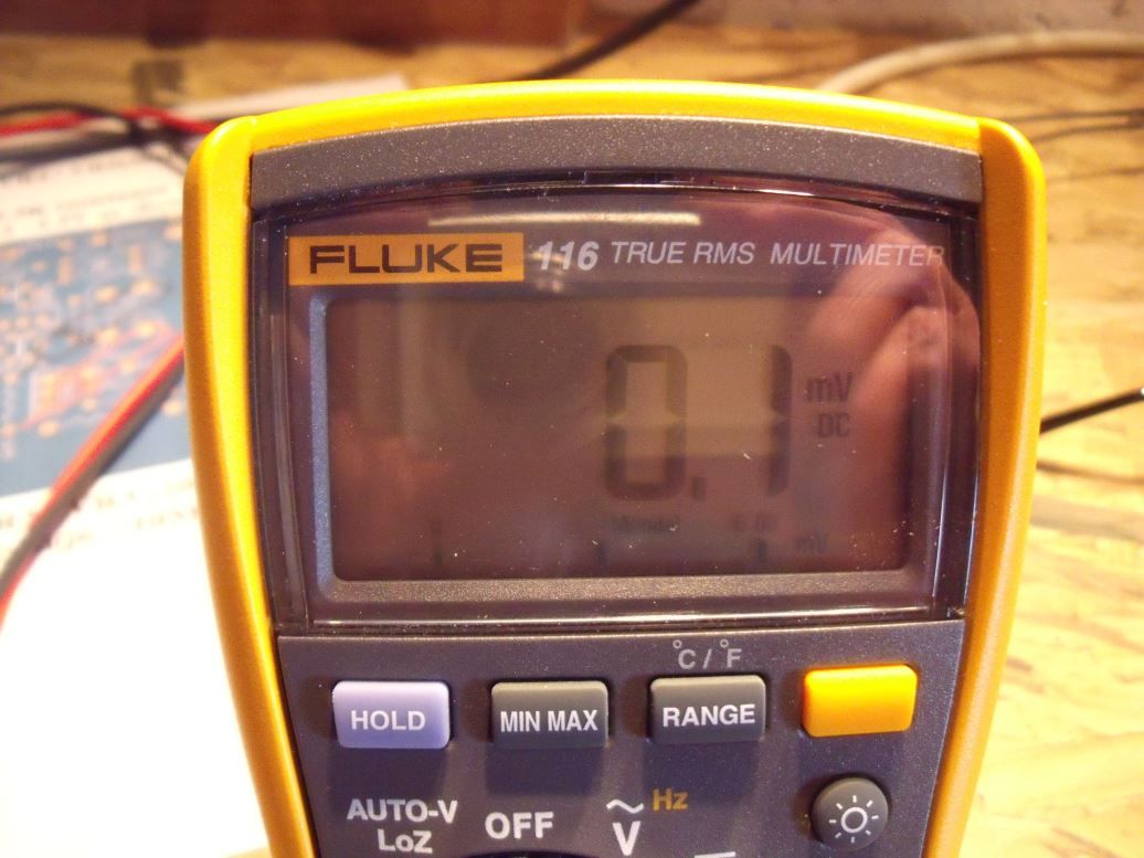
Frans, The voltage over the power caps is 28V. I got the amp all setup ready to slot into the new enclosure today.... postman arrives, hands me over the package that had duty on it and, guess what? It was a Pinkie from a customer who forgot to declare "returning to the UK no commercial value".... argh!! So... no enclosure from China today  Anyways, the transformer connections were exactly as I posted previously. Setting up the amp was a DODDLE! I set both 1k5 resistor voltages to 1.3V (by using the 500R trimpots) took about 10 seconds per side..... set the DC offset on both sides to 0.01mV ( you may get it to 0.00mV but it will usually fluctuate between 0.00mV - 3.0mV once the amp fully heats up. I set both sides to 0.00mV and left it running for 2 hours... when I re-checked it had gone up to 1.3mV and 2.1mV respectively which is more than good enough  I'll wait till everything is fitted in the enclosure and re-calibrate with everything in final position.    Measurements are pretty consistent from side to side and stable which is a very good sign.... nothing runs hot in this amp, the transistors with sinks attached pass the "finger on top for 10 seconds" test. Seems a damned good design to me and also shows that the parts are indeed "precision" parts.... no wide fluctuations from side to side.... measurements almost identical! Hopefully the enclosure will arrive tomorrow, I am itching to get this boxed up and have a good listening session.... I've left it on overnight with a 3kW fan heater blowing on it... it's about 70C flowing over it so as good a soak test as any  The day of reckoning is drawing closer and I "reckon" this is going to be one helluva good amp  |
|
leo
Been here a while!  Team wtf is it?
Posts: 3,638
|
Post by leo on Sept 3, 2010 20:48:38 GMT
Look forward to the updates, interesting design supplied with what looks to be a nice selection of parts so hopes are high it has the performance to match .
|
|
Deleted
Deleted Member
Posts: 0
|
Post by Deleted on Sept 3, 2010 21:09:50 GMT
28V is excellent.
In fact anything between 24V and 30V will be close to ideal and should not make much of a difference.
It can be a this wide a range because the amp has internal voltage regulators insuring proper operation of the whole amp over a wide voltage range.
IF the amp also runs at low temperatures in a closed enclosure you could even increase the current in the output stage a little.
I believe it will run hotter in an enclosure anyway because the dissipated 'warmth' is trapped inside and it will warm itself up.
So I guess there will be little room for increasing the output stages current.
Should you want to increase the current in the output stage (I guess it would be between 60-80 mA, Ur21 = 0.6V to 0.8V over 10 Ohms as it is now) you can replace DZ2 and DZ4 for 4.1V or 4.3V types or decrease the emitter resistors in value somewhat (R21,R22, R39,R40) but reckon the current configuration is fine and it will run in class-A for most HP's all the time even at high output levels.
|
|