|
|
Post by PinkFloyd on Sept 30, 2010 2:51:50 GMT
The Panda IS the Dog's bollocks..... no doubt about it, this is one VERY classy headphone amp. I reckon , if it was fully built up and on sale in an audio boutique you are EASILY looking at £750 minimum.
This is the best kit amp I have ever come across ..... it is pure class and I'd go as far as to say it is headpohne Nirvana.
Mike.
|
|
|
|
Post by bizzie on Sept 30, 2010 8:09:53 GMT
Well you've done it talked me into it I've ordered the kit ;D
The transformers coming from Rapid and I have a case I can use already so looking forward to getting the it, how long have they been taking to arrive mine was posted out yesterday?
|
|
Deleted
Deleted Member
Posts: 0
|
Post by Deleted on Sept 30, 2010 9:31:22 GMT
I have a new 30 VA 18v toroidal. Is that suitable or should I get a 50VA or 80VA?
Thanks
Syd
|
|
Deleted
Deleted Member
Posts: 0
|
Post by Deleted on Sept 30, 2010 9:34:27 GMT
Well you've done it talked me into it I've ordered the kit ;D The transformers coming from Rapid and I have a case I can use already so looking forward to getting the it, how long have they been taking to arrive mine was posted out yesterday? My case took 10 days but a further 3 days on and the kit hasn't arrived. They seemed to be posted at the same time. Syd |
|
Deleted
Deleted Member
Posts: 0
|
Post by Deleted on Sept 30, 2010 9:40:07 GMT
I have a new 30 VA 18v toroidal. Is that suitable or should I get a 50VA or 80VA? Thanks Syd Syd 30VA would appear to be ideal, as it uses 10ohm emitter resistors in the output stage.30VA may even sound better? Alex. |
|
Deleted
Deleted Member
Posts: 0
|
Post by Deleted on Sept 30, 2010 10:53:46 GMT
That's great Alex, thanks. I'm all set now, just need the kit to arrive!
Syd
|
|
Deleted
Deleted Member
Posts: 0
|
Post by Deleted on Sept 30, 2010 12:21:38 GMT
I know this is getting really sad BUT, I found one for Mick, once he's finished.....  Thanks Chris, that would do nicely, where did you get it from, unable to install it from your image. PS my super solder has just arrived so will make a start on the soldering on Tuesday as i am going away today for the rest of weekend. Mick. |
|
Deleted
Deleted Member
Posts: 0
|
Post by Deleted on Sept 30, 2010 12:38:43 GMT
Hi Mick
Just right click on the image and save it, its a jpeg
Syd
|
|
|
|
Post by PinkFloyd on Sept 30, 2010 14:23:00 GMT
I know this is getting really sad BUT, I found one for Mick, once he's finished.....  Thanks Chris, that would do nicely, where did you get it from, unable to install it from your image. PS my super solder has just arrived so will make a start on the soldering on Tuesday as i am going away today for the rest of weekend. Mick. There you go Mick  |
|
Deleted
Deleted Member
Posts: 0
|
Post by Deleted on Sept 30, 2010 15:24:57 GMT
Rock Panda's grotto.  |
|
|
|
Post by PinkFloyd on Sept 30, 2010 19:18:42 GMT
|
|
Deleted
Deleted Member
Posts: 0
|
Post by Deleted on Sept 30, 2010 19:30:08 GMT
Looking at how close those solder joints are makes me go sweaty, Mike. I would need a telephoto lens to see it.
I would imagine that those really close ones in particular could cause people problems ensuring that they don't touch or some debris doesn't bridge them,
|
|
|
|
Post by PinkFloyd on Sept 30, 2010 19:53:18 GMT
Looking at how close those solder joints are makes me go sweaty, Mike. I would need a telephoto lens to see it. I would imagine that those really close ones in particular could cause people problems ensuring that they don't touch or some debris doesn't bridge them, Ian, Unless you are really ham fisted it's pretty much impossible to solder two separate joints "together" as the surface of the board will not accept solder (only the pads will)..... of course, if you poured a bucket of molten solder over the board things may be different  The panda pads are pretty large.... try soldering SOIC chips, they are really small  |
|
|
|
Post by PinkFloyd on Sept 30, 2010 19:55:27 GMT
BTW..... that photo is quite deceptive, it looks like I have used too much solder but I haven't.... must be the lighting  |
|
|
|
Post by PinkFloyd on Sept 30, 2010 20:01:38 GMT
Looking at how close those solder joints are makes me go sweaty, Mike. I would need a telephoto lens to see it. I would imagine that those really close ones in particular could cause people problems ensuring that they don't touch or some debris doesn't bridge them, Toothbrush and isopropyl alcohol..... scrub the arse off the board with plenty of this (when you have finished soldering the PCB) until all debris is removed.... then soak some kitchen towel (the paper stuff) in isopropyl and rub it across the board.... it will automatically "shred" when the joints cut it to ribbons but this is good.... keep rubbing. Finish off with some dry kitchen towel and then a dry toothbrush (this will remove all the bits of paper)...... The entire board should look shiny clean. |
|
|
|
Post by clausdk on Sept 30, 2010 23:57:46 GMT
Looks very good Mike nice job..
I have enjoyed the Pandas company a couple of hours tonight and it still sounds awesome, to me it has a signature like the V8 but with a higher degree of detail/precision in the presentation, a bit deeper bass and also a blacker sourrounding than most amps on 230 volts..
It is clear that it just graps the driveres and control them so well it is hard to believe, It has been left on for some days now I hope that is ok as burnin ??
I really like the way Siblans has just gone on a hike.
|
|
Deleted
Deleted Member
Posts: 0
|
Post by Deleted on Oct 1, 2010 7:21:30 GMT
Claus, it's funny you mentioned the V8. I'm intending to compare the two. Mike has warned me that it could change my views on the X-Cans!!! (That worries me because I am really fond of the V2 in particular)
I wasn't that keen on the 'tone' from the V8 on the K701's at first when I put the buffer in line but with time, either my ears became accustomed, the buffer settled down or I was mistaken.
I felt that the bass still wasn't quite right for me but after a while, I was listening and it suddenly struck me that actually, this is a 'transparent' sound and the bass actually IS there. It just blends well with the rest of the spectrum.
I've stuck with this combo ever since I wired up the buffer so that I'm really accustomed to it before the Panda arrives. If it's better, I'll be over the moon. It sounds as though it is extremely good and I'm really grateful to Mike 'cos he's working his socks off up there. (Although he hates not having them on, I know!!)
|
|
Deleted
Deleted Member
Posts: 0
|
Post by Deleted on Oct 1, 2010 11:41:44 GMT
Thanks Chris, that would do nicely, where did you get it from, unable to install it from your image. PS my super solder has just arrived so will make a start on the soldering on Tuesday as i am going away today for the rest of weekend. Mick. There you go Mick  Thanks Mike, the solder has arrived will get my board populated by this time next week. Helipanda. |
|
Deleted
Deleted Member
Posts: 0
|
Post by Deleted on Oct 1, 2010 12:02:07 GMT
Looking at how close those solder joints are makes me go sweaty, Mike. I would need a telephoto lens to see it. I would imagine that those really close ones in particular could cause people problems ensuring that they don't touch or some debris doesn't bridge them, Toothbrush and isopropyl alcohol..... scrub the arse off the board with plenty of this (when you have finished soldering the PCB) until all debris is removed.... then soak some kitchen towel (the paper stuff) in isopropyl and rub it across the board.... it will automatically "shred" when the joints cut it to ribbons but this is good.... keep rubbing. Finish off with some dry kitchen towel and then a dry toothbrush (this will remove all the bits of paper)...... The entire board should look shiny clean. Funny enough i purchased some PCB cleaner with my solder, so will finish off as above when all components are in situ. Mick. |
|
|
|
Post by PinkFloyd on Oct 1, 2010 20:01:59 GMT
There you go Mick  Thanks Mike, the solder has arrived will get my board populated by this time next week. Helipanda. All the best with the build Mick, you'll be fine  I'm just awaiting the second enclosure to arrive and then I'll get cracking with Ian's Panda. Seems the kits arrive pretty fast but the enclosures take a bit longer..... I may try a different layout with Ian's, with the transformer at the front and the PCB towards the back.... much shorter input leads but of course the output leads will be longer, what you gain on the swings you lose on the roundabouts. |
|
|
|
Post by PinkFloyd on Oct 1, 2010 20:27:56 GMT
Toothbrush and isopropyl alcohol..... scrub the arse off the board with plenty of this (when you have finished soldering the PCB) until all debris is removed.... then soak some kitchen towel (the paper stuff) in isopropyl and rub it across the board.... it will automatically "shred" when the joints cut it to ribbons but this is good.... keep rubbing. Finish off with some dry kitchen towel and then a dry toothbrush (this will remove all the bits of paper)...... The entire board should look shiny clean. Funny enough i purchased some PCB cleaner with my solder, so will finish off as above when all components are in situ. Mick. There's a great place up here in Wick.... called the Caithness Chemical company..... they sell everything from concrete cleaner to grafitti remover, you name it they have it..... a real old fashioned company too with hand written receipts (not a computer anywhere).... anyways, I get a 5 litre bottle of Isopropyl from them for £3.99 !! Yep, £3.99 ! Buy it in a chemist (IF they'll sell it to you) and it'll cost you a fiver for 500ml.... buy it in an "audio boutique" relabled as "tape head cleaner" and it'll cost you a fiver for 50ml of the stuff  You really cannot beat the stuff, it cleans beautifully and evaporates in seconds.... it's also nice with coke and ice (joke)..... just like butyl rubber tape, the isopropyl is something I couldn't live without. Mick, you may not "think" you need butyl rubber tape but, trust me, a roll of this stuff will last you for YEARS and it will be something you reach for almost every day of your life.... this gear will adhere to WATER.... I use it for everything, mounting SOIC chips, waterproofing solar lights, deadening speaker enclosures, hanging things on the wall (this stuff will hold a giant mirror in place on a wall!)..... hundreds of uses.... the only thing it won't stick to is your skin, the more you work it in your fingers the stickier it becomes but it never sticks to your skin. WD40 was heralded as a "must have" back in the day. I agree, WD-40 is good stuff but I use it maybe twice a year... the butyl rubber tape I use almost every day..... fantastic stuff! At the moment it's only really known by people who fit windows but I'm sure the magical properties of this stuff will be realised by some entrepreneur who will sell it for big bucks in a small package calling it a wonder substance.... it's only a matter of time  You can buy a GIGANTIC roll of the stuff (19 metres) from reddiseals for under a fiver www.reddiseals.com/acatalog/glazing_tapes_butyl_sealant.html If I ruled the world I would supply every home in the land with a roll of this gear.... it is the most indispensable item you didn't know you need! Has, literally, hundreds of uses and quite a few most suited to audio equipment  Sorbothane feet? bin them! Roll up some of this gear into balls and place under the feet of your equipment you will be amazed  |
|
|
|
Post by Koolind on Oct 2, 2010 12:13:13 GMT
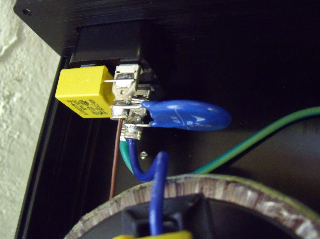
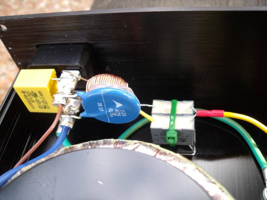
 Shoved a 275V EPCOS varistor and a 470nF class X2 cap across the line. I will be adding a class Y2 between L/E and N/E tomorrow...  What is the purpose of these additional components? To "filter" the power input? |
|
|
|
Post by PinkFloyd on Oct 2, 2010 13:52:46 GMT
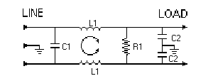
More of a belt and braces type effort.... the class X2 cap across the line (L/N) suppresses noise and the 275V MOV varistor basically offers a bit of surge protection. You can also add class Y2 caps between live and earth and neutral and earth they basically add protection where failure could lead to electric shock if the ground connection were lost. You can also fit a 1M bleeder resistor across the line (L/N) and a 22mH common mode choke....  C1=0.47 uF (the X capacitor) C2= 22nF (the Y capacitors) L1=22 mH common-mode choke R1=1M ohm bleeder resistor The above diagram does not show the 275 MOV varistor. |
|
|
|
Post by PinkFloyd on Oct 2, 2010 13:56:53 GMT
 Just the bleeder resistor to be fitted. None of this is necessary and quite a few people frown at using filters.... I just like the belt and braces approach  |
|
Deleted
Deleted Member
Posts: 0
|
Post by Deleted on Oct 2, 2010 14:20:43 GMT
 Just the bleeder resistor to be fitted. None of this is necessary and quite a few people frown at using filters.... I just like the belt and braces approach  Mike Are you going to encase it in heatshrink after you are satisfied that you have optimised it ? 230VAC is very unforgiving in inexperienced hands. (not yours !) Alex |
|