Deleted
Deleted Member
Posts: 0
|
Post by Deleted on Feb 5, 2011 9:22:40 GMT
I just wondered if anyone here has tried the new Panny FR series caps.
They are supposed to have longer life than FMs (10,000 Vs 7,000 hrs @ 105ºC), have same ESR & impedance values (FRs in some models a tad better) and are smaller for the same uF so a 1,200uF FR is 12.5mm x 25mm ie exactly the same size as a 1,000uF FM or a 1,000 uF FR is 5mm shorter than same value FM.
Difference in price is very small, at least at Farnell's site. Only problem is you have to order them in 5s.
|
|
XTRProf
Fully Modded
Pssst ! Got any spare capacitors ?
Posts: 5,689
|
Post by XTRProf on Feb 5, 2011 22:55:04 GMT
I just wondered if anyone here has tried the new Panny FR series caps. They are supposed to have longer life than FMs (10,000 Vs 7,000 hrs @ 105ºC), have same ESR & impedance values (FRs in some models a tad better) and are smaller for the same uF so a 1,200uF FR is 12.5mm x 25mm ie exactly the same size as a 1,000uF FM or a 1,000 uF FR is 5mm shorter than same value FM. Difference in price is very small, at least at Farnell's site. Only problem is you have to order them in 5s. If it's cheap, just order them and try. No need to wait for any comments on them as most Pany are very good value for it's price. Just make sure they are a continuation from the FM and FC series which are grouped togather in the Pany catalogue under low ESR category. The only "highend" Pany that I know is the XP series which is supposed to be better than the FM and FC series. The XP is in the same category as the Nichicon Muse. But usually the Pany sounds better than any Nichicon according to reviews. I have not done a side by side audition on the XP with other similar yet. So far the highend E-CAPS IN DESIGN that I know are the Mundorf, Elna Cerafine and Silmic, BG and Sanyo Oscon. Have done a pow-wow on some of them and I rate, according to my ears, the Elna Cerafine the highest follow by the BG and the Oscon last. Will be trying the Silmic later. Mike can definitely chip in on this as he has extensive experiences on using many e-caps. But now he is enjoying his "CNY holidays" for about a week before he is back next Monday.  Fyi. |
|
|
|
Post by PinkFloyd on Feb 6, 2011 1:18:56 GMT
They look pretty good, not dissimilar to the Panasonic NHG range. There is also the Panasonic FK which are slightly smaller than the FM series.... I would never overlook Panasonic capacitors, they are excellent quality. The extended lifespan is a big plus, I may buy a few of these and try them out....
|
|
Deleted
Deleted Member
Posts: 0
|
Post by Deleted on Feb 6, 2011 9:53:30 GMT
Thanks to both for for your answers. I think I'm going to order 10 x 1,200uF to replace all 1,000uFs on PS board. 20% extra capacity, same size and 50% longer life for an extra 2 € sounds good to me (1.01€ Vs 1.21€). As I'm a total noob I've been reading a lot about caps and I think I'm starting to get the picture but just that, starting. Most people seem to agree that boutique caps make no sense in PS coupling but may show benefits in audio path. I've checked here: industrial.panasonic.com/www-ctlg/ctlg/qABA0000_WW.htmlAnd can't find the XP series, do you have a link where I can read about them? Now the homework for Mr. Floyd when he gets back...  or anyone who can help: I had a great time reading almost all post in the 20 pages of this sub forum and sure I did learn some but now I have some questions for the experts. In another thread Mike posted this about X-Cans V1: -"In the PSU board Fit Panasonic 1200uF, a couple of Panasonic FM 100uF, Six UF4007 ultrafast diodes and replace the 470nF orange film cap with an EVOX PHE426 polypropylene. On the bottom board replace all of the 10uF electrolytics with non polar types (10uF), replace the 4 x 100uF with Panasonic FM, remove R115 / R225 and fit 32 ohm resistors here, remove the 4 x orange 470nF film caps and replace with EVOX PHE 426, fit Dip 8 sockets and roll in 2 x OPA2134 and you will be in heaven. LM4562 will also be fine here."- Upper board:When I changed the valves I saw that two of the caps (the two 1,000s that are closest to the two 100s) have bulged so maybe all of them are somewaht deteriorated further than regular aging (+10 years) and use. 1) Is it OK to replace all caps (1,000 & 470) with 1,200? or having too much capacity can have a negative side (ie 1,200s slower than 470s) and I should stick to 470uF? My Q's are: Lower board:2) Would it make sense to use Silmic II (or any other reasonably priced boutique cap) instead of Pannys to replace the 100uFs? 3) What about Nichicon Muse ES (non polar/bipolar) for 10uF? 4) I've only read once Mike recommend changing R115/R225 from 47 to 32 Ohm, is this still valid or experience made you reconsider? 5) In most V2 and V3 removal of input caps (mmmhhh... or was it output? or both?) if there is no DC present on source output. My current source is a Musiland Monitor 02, which for the £73 I paid including shipping is a fantastic piece of kit, and I read at headfi that a user of a different Musiland kit had some DC present so I have to check my 02s but if there is none present could a relace any of the caps for 0 Ohm links/ferrite beads? which ones? 6) I want to do some opamp rolling (already ordered some free samples from TI - OPAs 2107, 2111 & 2132) and wondered why Mike dislikes so much de LM4562/LME49720 - he always recommends 2134 or 2107 - in the X-Cans and also if a double AD797 on a browndog adapter could be used in this position, it has a great reputation for its SQ but also of being a difficult chip to implement. Are the differences in sonic signature between these really so small in the V1? 7) In one of the V8 threads Mike commented about MF's "Tuning service" so I checked it out for V1 - Realign volume control (I'll replace it with Alps mini) - Replace all audio path electrolytics with low ESR, high temp. type (just like Mike says) - Replace bypass caps from ceramic to polycarbonate/polyester ((just like Mike says) - Pure copper noise nulling screen fitted to PSU caps (WTF) - Bypass PSU electrolytics with polycarbonate/polyester type (just like Mike says) - Replace ceramic bypass caps with polycarbonate/polyester type (just like Mike says) -Replace regulators with selected premium types (any thing to be gained out of this?) - Precision re-bias (making sure nothing's wrong?) - Replace PSU caps with low ESR high temp type (just like Mike says) - Replace 2x ECC88 tubes with precision matched pairs (just like Mike says, make it matched 6N23P-EVs please) - Heater current, audio characteristics and transconductance matched (same as above) - Replace 4x medium power output transistors with precision matched pairs (worth it?) - Log owner name, model and serial number in Musical Fidelity archives (what an honor!!) - Issue certificate signed by Antony Michaelson(I'd frame it and hang it above the fire place) - Soak test for 48 hours (making sure nothing's wrong for the second time?) |
|
|
|
Post by PinkFloyd on Feb 6, 2011 12:17:31 GMT
Javier, I will answer all these questions later on.... I'm in the middle of painting @ the moment  |
|
|
|
Post by PinkFloyd on Feb 6, 2011 16:13:27 GMT
I have just bought 500 of these and it is great news as the 35V /1800uF FR are the exact same dimensions as the 35V / 1200uF (12.5 x 35mm) so now we can fit extra capacitance to the V1 / V2 boards and it will fit comfortably! The PSU board on a V2 (for example) comes with 10,000uF (10 x 1,000uF).... with the 1200uF FM caps that increased to 12,000uF.... the 1800uF FR caps will give us a whopping 18,000uF, PLUS an even longer lifespan than the 1200uF FM's. More capacitance is definitely better on the PSU board.... I have tried a V2 with 2200uF caps fitted and it sounds AWESOME, unfortunately there is no way of cramming 10 x 2200uF into the can, it just won't fit due to the sheer size of the capacitors. The 1800uF FR caps will fit PERFECTLY! Great news for V1 / V2 owners!  |
|
|
|
Post by PinkFloyd on Feb 6, 2011 16:16:03 GMT
By the way..... I appear to have bought up all of RS components stock  they only have two 1800uF / 35V FR's left  Just bought another 150 from Farnell  |
|
Deleted
Deleted Member
Posts: 0
|
Post by Deleted on Feb 6, 2011 16:37:46 GMT
By the way..... I appear to have bought up all of RS components stock  they only have two 1800uF / 35V FR's left  Just bought another 150 from Farnell  wow!!! 650 caps in one go!!! Hope that paint job doesn't take too long and, please, don't buy all Farnell's stock too. PS. I just saw the 1,800 are 35mm tall, will they fit in V1 or v2? |
|
Deleted
Deleted Member
Posts: 0
|
Post by Deleted on Feb 6, 2011 17:05:37 GMT
By the way..... I appear to have bought up all of RS components stock  they only have two 1800uF / 35V FR's left  Just bought another 150 from Farnell  Piggin' 'ell Mike! I just had a quick wazz around Farnell global. As far as I can see, they have 45 units left in the UK (which = ALL for europe!) and another 150 in Singapore. Get 'em quick Chong, Mike's buying the world  |
|
Deleted
Deleted Member
Posts: 0
|
Post by Deleted on Feb 7, 2011 14:52:59 GMT
Mike, While waiting for your answer I've been googleing trying to learn a little and found this: www.allaboutcircuits.com/vol_2/chpt_11/3.html3rd paragraph starting from the bottom says: -"It should be noted that too much capacitance in an AC circuit will result in a low power factor just as well as too much inductance" Supposing too much inductance is not desiable (haven't got a clue 'bout this), isn't going from 8 x 1,000 + 2 x 470 (V1) = 8,940uF to 10 x 1,800 = 18,000 considered "too much capacitance" (201% increase)? wouldn't 10 x 1,200 be a safer middle ground (134% increase)? Cheers |
|
|
|
Post by PinkFloyd on Feb 8, 2011 20:09:08 GMT
The X-CAN Power board is DC  In this particular application MORE capacitance is better... in fact, a few years ago the guy who designed the X-CAN told me that it's not the "quality" of the capacitance that matters it's the "amount".... due to the "size" of the V2 enclosure all they could cram in was 1000uF caps.... ideally they would have used 2200uF but couldn't fit them onboard..... X-CAN V3 used (you guessed it) 2200uF caps  ...... V8 also used 2200uF but I upped that to 3300uF in my mods with MOST desirable results ( V8 mods here)..... so, MORE capacitance is BETTER on the V1 / V2 power boards. The Panasonic FR arrived today: 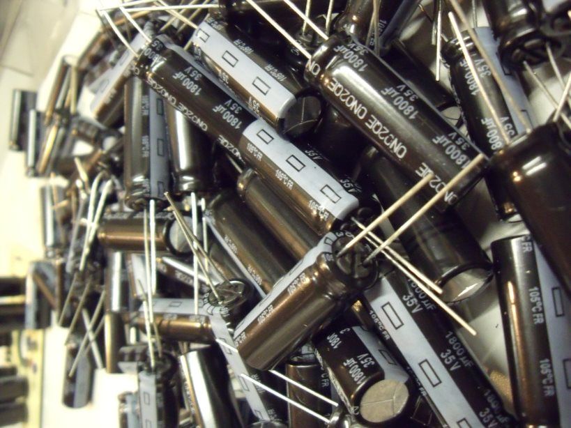 They are black with a grey stripe running down the neutral side.... they are a bit longer than the 1200uF but the same width: 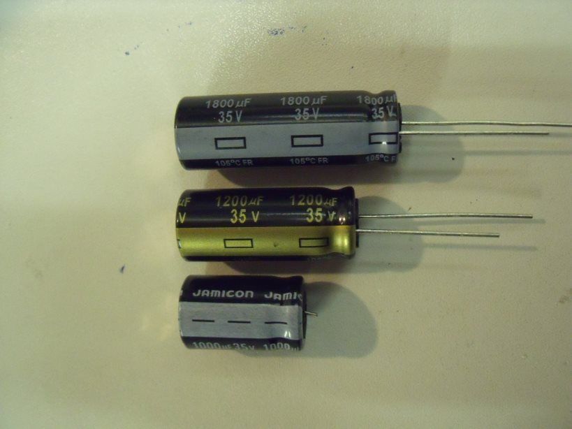 Bottom is stock Jamicon 1000uF, middle is panasonic FM 1200uF, top is Panasonic FR 1800uF. I was a bit worried that they may be a bit too tall for the V1 / V2 so I cracked open one of my stock V2's for a measure up.... they all seemed as if they would "just" fit so I decided (while I had the V2 apart) to put them to the test  As you can see... there is literally only 1mm to play with in parts so these 1800uF Panasonic FR caps must be mounted flush to the board... if you mount them straight they are a PERFECT but TIGHT fit.... just what the Doctor ordered! 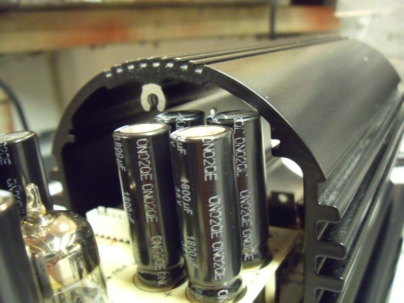 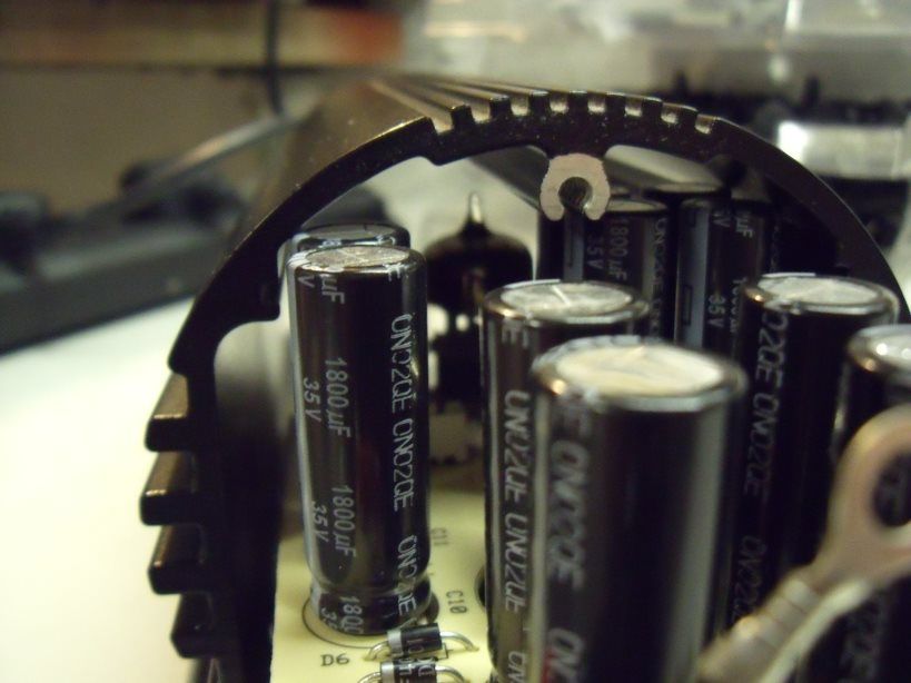 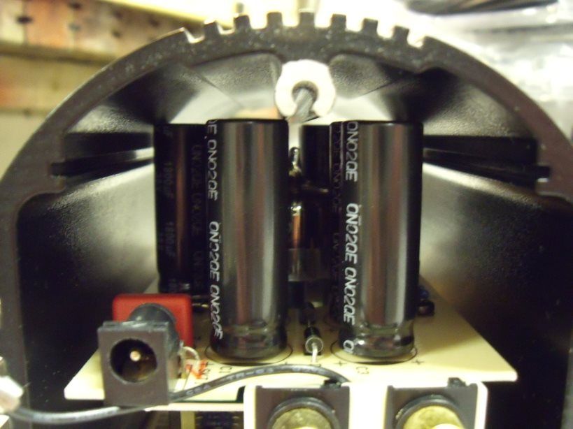 See what I mean by a tight fit?  OK, no point doing half a job so I also fitted UF4001 (ultrafast) diodes to the PSU board.... UF 4001 are even faster than UF4007 (50ns V 75ns) and these are what I supply with my kits now. The bottom board was fitted out with 10uF MUSE non polar input caps, 1000uF MUSE non polar output caps, Panasonic FM 100uF, Ceramic valve sockets, Jalco Pro head socket, ALPS potentiometer, new quad phono socket and a pair of UBER fantastic 6N23P-EB Russians: 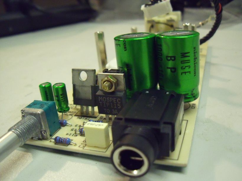 Jalco, MUSE, ALPS pot 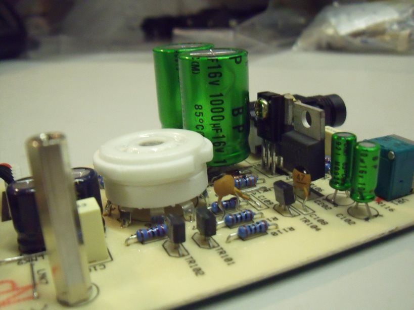 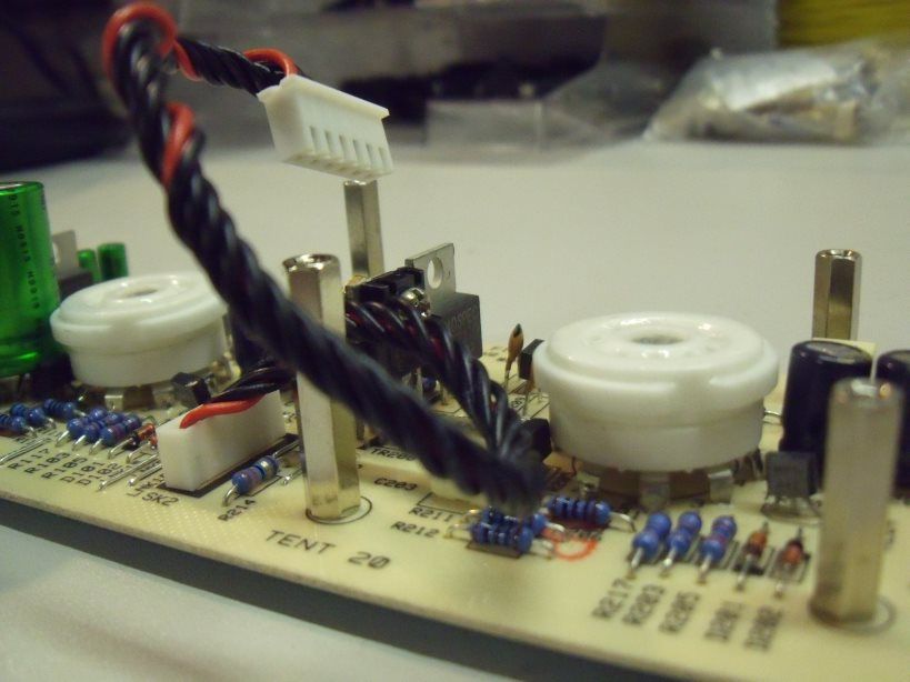 Ceramic valve bases 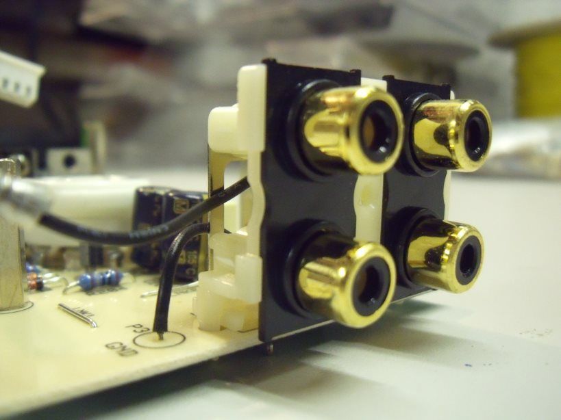 Quad phono socket 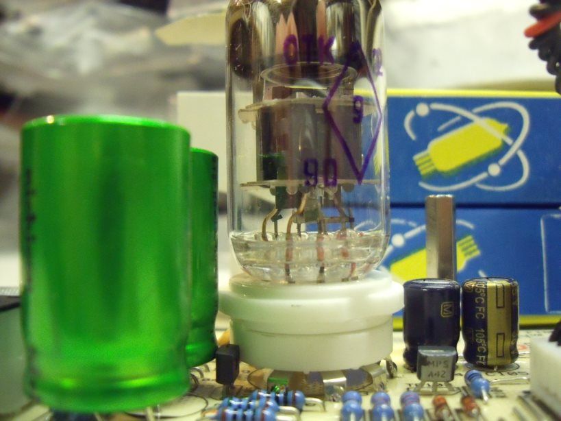 6N23P-EB fitted 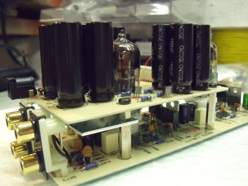 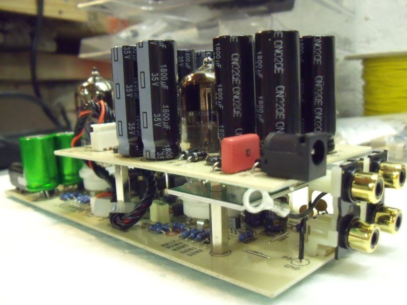 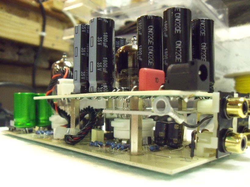 Both boards connected 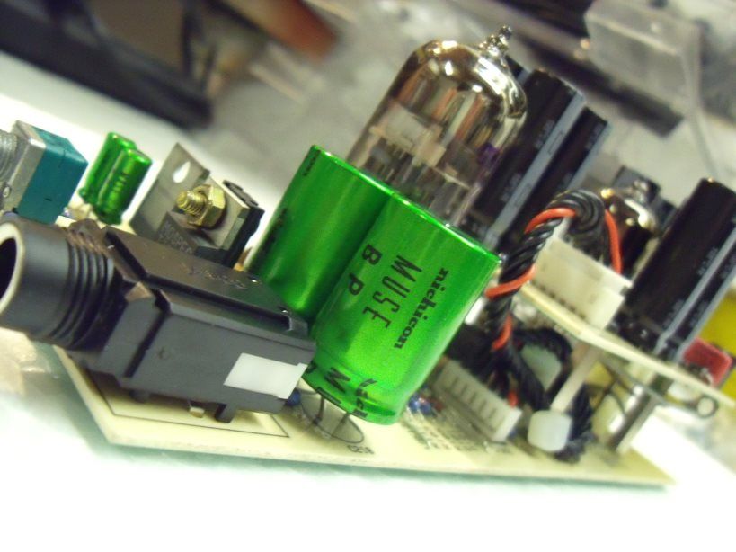 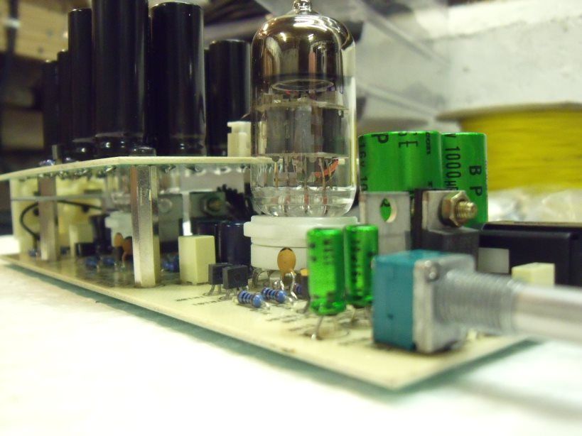 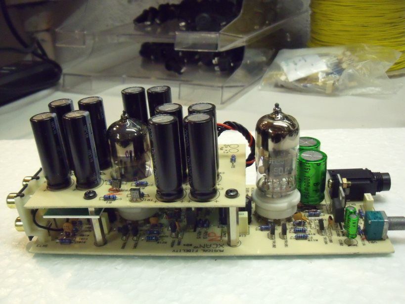 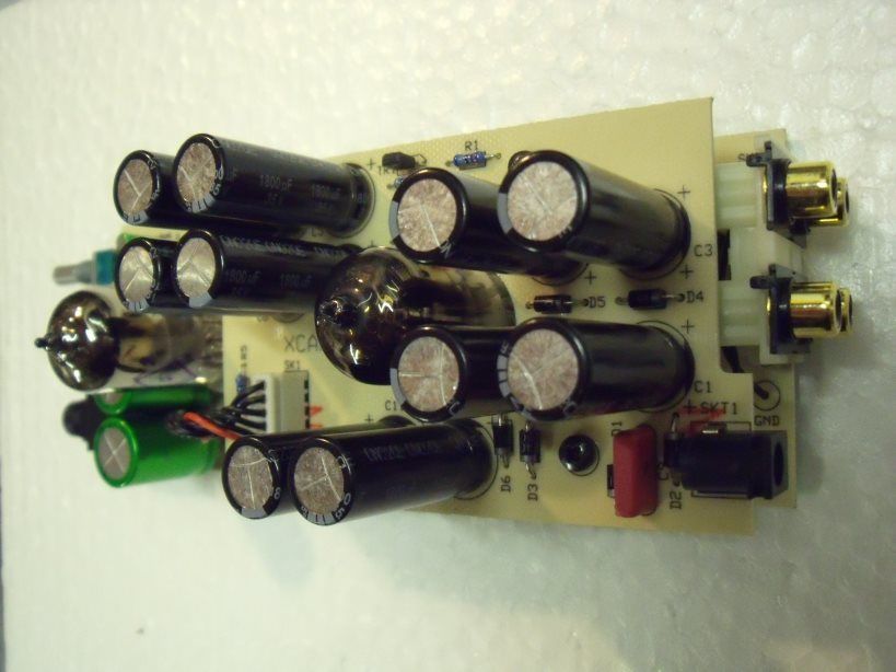 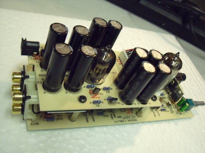 A few more random shots 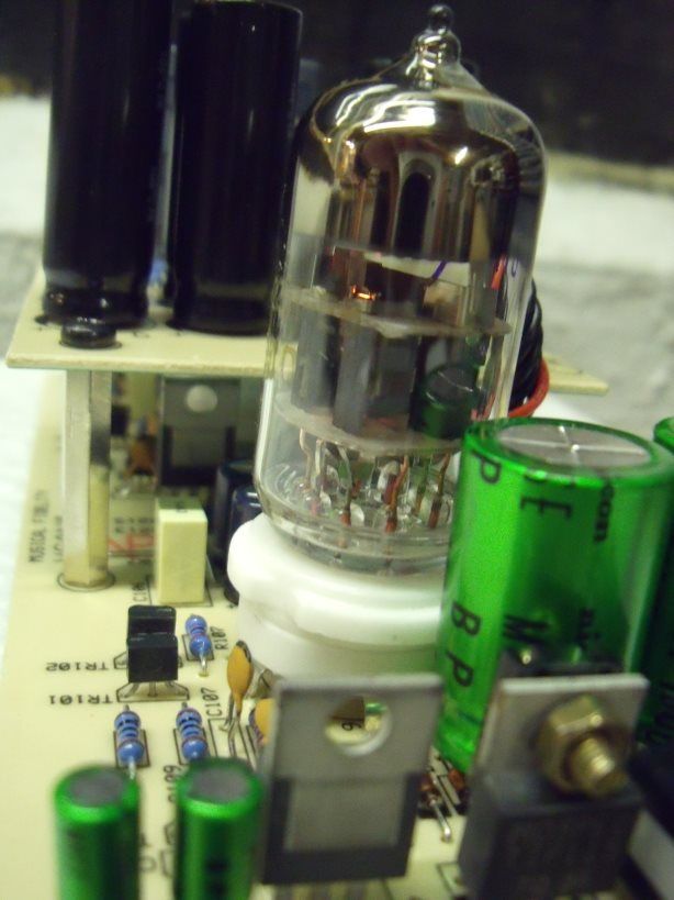 Powered up ready to go! Just as before, when I experimented with 2200uF in the V2, there is a VAST improvement in dynamics, spaciousness, bass response, width, depth.... you name it, it is clearly better across the spectrum and it's only been fired up for the last two hours!! Absolutely fantastic!  |
|
|
|
Post by PinkFloyd on Feb 8, 2011 20:30:57 GMT
I think I'm going to order 10 x 1,200uF to replace all 1,000uFs on PS board. 20% extra capacity, same size and 50% longer life for an extra 2 € sounds good to me (1.01€ Vs 1.21€). Yup, that is the way to go... more capacitance = better here  Low ESR caps are best here and the panasonic FM is pretty much as low as they go PLUS you have the added benefit that they are 105C temp. rated so, NO, you would be wasting money fitting boutique jobs here. Perfectly good, these are the non polars I use, they work very well in the X-CAN amps. Use your ears on this one... you will note a "small" but noticeable difference, all depends on what you like..... resistors cost pennies so this is not an expensive area to experiment with  If you are certain there is no DC on your source's output then you can remove the two 10uF caps adjacent to the headphone socket.... jumper over the pads with either a wire link or an axial ferrite bead.... Fran's reckons the ferrites do nothing "technically" but I think they do  I would not use the AD797 unless you know how to implement it correctly, it is not a direct "roll in" replacement for the 5523. The 2132 / 2134 and 2107 are pretty much bullet proof and you are safe to roll these in without having to optimise the surrounding circuitry.... you could also try the OPA 2227 ( a lovely smooth sounding chip) but stay clear of the OPA 2228 as it is slightly more cranky. LM4562 is also fine but I, personally, don't like it's signature in the V1.... way too neutral for my taste. Apart from the signed certificate and the copper thingway all I can say is.... erm.... looks very similar to the mods a certain chap has been doing for many years  From what I can gather the low ESR / high temp. caps they use are from the well known "Jamicon" stable  |
|
|
|
Post by PinkFloyd on Feb 8, 2011 23:16:37 GMT
Javier,
I will crack open a V1 (X-CANS) tomorrow and perform the same mods on it just to ensure that the 1800uF are a comfortable fit inside it, I will let you know (with a few pics).... I'll mod the V1 from the ground up and hopefully this will help you with your mods.... I will take pics of each stage of the operation.
The V2 fitted with the 1800uF Panasonic FR caps has been playing on loop for about 5 hours now and it is sounding stunningly good! There is a certain grandiose to the presentation now, a greater sense of scale, more fluidity in the mids and, overall, a lovely mellifluous tone.
Dynamics are smack you in the face good.... the pace rhythm and timing just spot on.... I'll leave her playing away overnight and will report back tomorrow.
|
|
mrarroyo
Been here a while!  Our man in Miami!
Posts: 1,003
|
Post by mrarroyo on Feb 8, 2011 23:35:17 GMT
I hate you Mike! Not really, I need to put an order for a few of the Russian tubes so I might as well order a set o these larger caps for the V2 and V1 I have here that you modded. I will wait until you test them fitting inside your V1 and also for your feedback on the sound improvements.
|
|
|
|
Post by PinkFloyd on Feb 8, 2011 23:39:03 GMT
Not a lot! I usually buy 1,000 x Panasonic FM at a time.... if you buy 1 capacitor it costs you £0.89 pence (not including VAT) if you buy 1,000 they are £0.37 pence each.... a BIG difference! Of course, if you only "need" one then there is no point in buying 1,000 but if you go through a lot of them then it is sensible to buy in multiples of 1,000. Unfortunately neither RS or Farnell had 1,000 in stock or I'd have bought 1,000 of them  |
|
|
|
Post by PinkFloyd on Feb 9, 2011 0:30:51 GMT
|
|
|
|
Post by PinkFloyd on Feb 9, 2011 8:09:19 GMT
Javier, You may also be interested to learn about the lifespan ratings of a capacitor. When it says 10,000 hours at 105c this means the capacitors lifespan will be 10,000 hours operating at a temperature of 105C. Now, lets say the capacitor is only subjected to, say, 35C ambient temperature you can expect the capacitor for many many years within spec.... I don't know the exact formula for working it out but these capacitors in an X-CANS (for example) will possibly be good for 15 - 20 years! The 10,000 hour figure ONLY applies if the capacitor is subjected to 105C constantly.... maybe Frans would like to chip in here? I do have chart somewhere which tells you how long an 85C capacitor will last when operated at 75C / 65C / 55C /45C / 35C / 25C etc. etc.... I must look it out. One thing is certain, fit these in your X-CANS and they will be good for MANY many years. Another fantastic long life capacitor (which I also use in X-CAN amps) is the Samwha VA series... rated @ 130C with a load life of 4,000 hours they will probably last as long as the FR caps... the extra +25C over the FR will add to their lifespan if operated at relatively low temperatures (35C - 55C)... they are low impedance too. If you want a "sexy" looking cap then look no further than the Samwha VA, it is sheathed in a lovely gold wrapper.... IMO there is not a lot in it between an FM and a VA, the FM being slightly more liquid and the VA slightly more organic sounding.... The VA seems to have been overlooked in the audio circles and I don't know why.... low ESR, 4000 hour load life @130c, nice sounding and relatively cheap... ie: you can pick up a 35V / 100uF for 10 pence each or 6 pence each if you buy 500. RAPID stock a few values and, for some reason, seem to be gradually phasing them out of their capacitor range.... I got in fast when they were phasing the 50V / 1000uF out and bought 500 of the bastards for something crazy like £100! Always keep a look out on these sites, when they start clearing stock you can get some good bargains! Righty ho!.... I promised you last night that I would do a step by step guide in modding a V1 so I better get my skates on and get to work on it.... I'll do a total stripdown and take pics of each step, will post the pics later on (unless I am distracted by something else).... Wednesday is my day off / paerwork day but I'm sure I can squeeze an X-CANS (V1) mod into my day  Mike. |
|
|
|
Post by PinkFloyd on Feb 9, 2011 8:10:50 GMT
I hate me too! Never satisfied mate, always searching for the last "nth" of SQ... it's a never ending battle  |
|
mrarroyo
Been here a while!  Our man in Miami!
Posts: 1,003
|
Post by mrarroyo on Feb 9, 2011 11:31:58 GMT
You do a fine job mate, glad you do all the "leg work". Thanks.
|
|
Deleted
Deleted Member
Posts: 0
|
Post by Deleted on Feb 9, 2011 17:29:42 GMT
I've been trying to post all day but they just won't let, I'm the IT guy of the company and today is being one of "those" days... I'll just say a huge THANKS to Mike (      ) and I'll try to post when (or IF) I get home tonight. |
|
|
|
Post by PinkFloyd on Feb 9, 2011 20:26:49 GMT
I modded the V1 this afternoon and all went well with the 1800uF caps, I will have to upload pics tomorrow as I haven't slept for almost two days.... Night night  |
|
Deleted
Deleted Member
Posts: 0
|
Post by Deleted on Feb 10, 2011 14:47:46 GMT
So far I've replaced diodes with UF4004s, fit DIP sockets, replaced all 1,000 & 470 with FR 1,000uF (it is just 15min drive to RS's warehouse in Spain), all 100s with FR 100uF and 10s with 10uF FC. I asked a very nice fellow from the Asset Management Dpt. I knew to be into DIY to bring his iron to the office and teach me how to use it. He did the opamp removal from the board (they both survived and work fine) and put socket for opamp rolling as we agreed that it was too complicated for a first timer. He also did 1 cap and 1 diode so I could see how it was done. I grabbed an old broken PS from a PC and practiced a little desoldering and resoldering back some caps. After half an hour practice I had enough condifence to try on X-Cs. All went fine with a “minor” incident. I damaged a track when trying to remove of the diodes. One of its legs was bent real hard against de board so I used a fine screwdriver to try to separate it but lifted the track along with the leg. My friend came to rescue me and soldered of the new diodes legs directly to the leg of the cap that was next along the same track and it works just fine. So all in all my "first time" soldering went quite well, I did 23 of the 24 caps plus 5 of out 6 diodes. The most important part is that I actually enjoyed working with the iron and will be happy to do it again. When I finished the working and went for the fun part I thought the improvement in SQ would be there, subtle but easy to hear. Mate I was wrong. I’m using a Musiland Monitor 02 US USB DAC as the main source the other being a Rotel RCD971, and my cans are AKG K 501 and 601 (use the 601 most of the time). For starters now my X-Cans are louder than before. I always listen to music at low to moderate levels. Before modding I never went beyond 10 o'clock and most of the time I would listen with the knob between 7 and 9. After the modding I even find 9 o’clock loud, is this normal? Will it go back to the way it was before with a little burn-in? As to the rest… well I’m not good with adjectives but the change is BIG. Yesterday I listened with the original NE5532s to check the effect of the upgraded caps and diodes. The bass was better, faster and tighter but I think the bigger improvement was in the mids and highs, adding sweet “sparkly” detail and depth that weren’t there before. Most probably the original caps were already too degraded (some of the upper board had bulged tops) so even if replaced with the same value now the circuit is back to new condition and that explains why such a difference even the most die hard “level matched xxxxxx all sound the same” would have to admit. Forgot to mention that I’m not using the MF walwart that was burned by a surge, I’m using a cheap (<20€) but heavy (900g) and powerful 1200mA unit with a E type trafo (or whaterver it is called). As I write this I’m listening with the LM4562 opamps and so far I’m very impressed but as I’ve changed too many things in too little time (valves, caps, diodes and opamps) is hard to tell which one contributes more. This weeked I’ll try the 2134s and see if I can find out why Mike likes them so much. I've already mailed Mike asking for some more parts to change/upgrade, once you start it is hard to stop  . Now, some more questions. 1. Is it pointless to replace 4 x med power trannies and all regulators for higher quality/specs ones? (As in MF's fine tuning) 2. I can’t find R225 on the board but there is R215 beside R115, did you mean that Mike? Is this the same “gain mod” as in the V2, because I wouldn’t mind a little more usable travel for the knob. 3. Mike, how does your newly modded V1compare to a SS like the Panda? |
|
|
|
Post by PinkFloyd on Feb 10, 2011 20:05:37 GMT
Javier, As promised here is the info on using the Panasonic FR 1800uF with the V1. Only one minor snag on the PSU board with one of the caps and I'll cut straight to the chase.... you have to bend one of them over to get the PSU board to fit back into the enclosure. I don't like funky angling of any component, I always like to do a neat job so here is my workaround. First off remove R2 and TR1 and mount them on the bottom of the board: 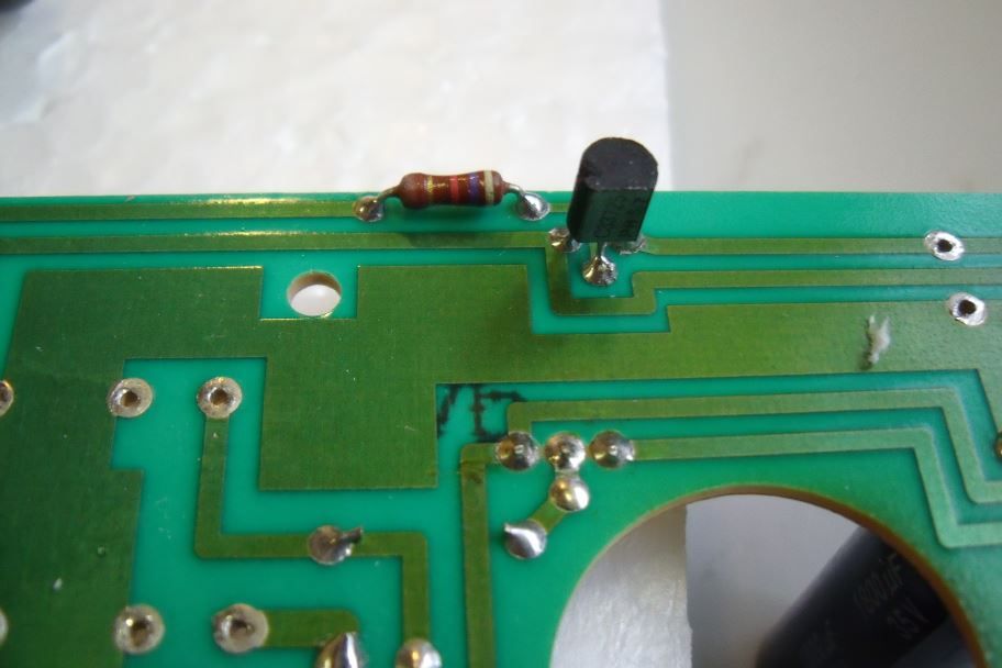 We are going to lay the cap flat on it side, now we have a nice flat bed to lay it on... next thing is to fix some double sided sticky tape into position: 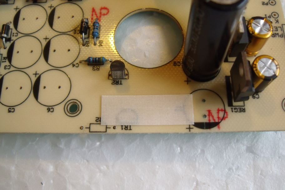 Peel off the top layer: 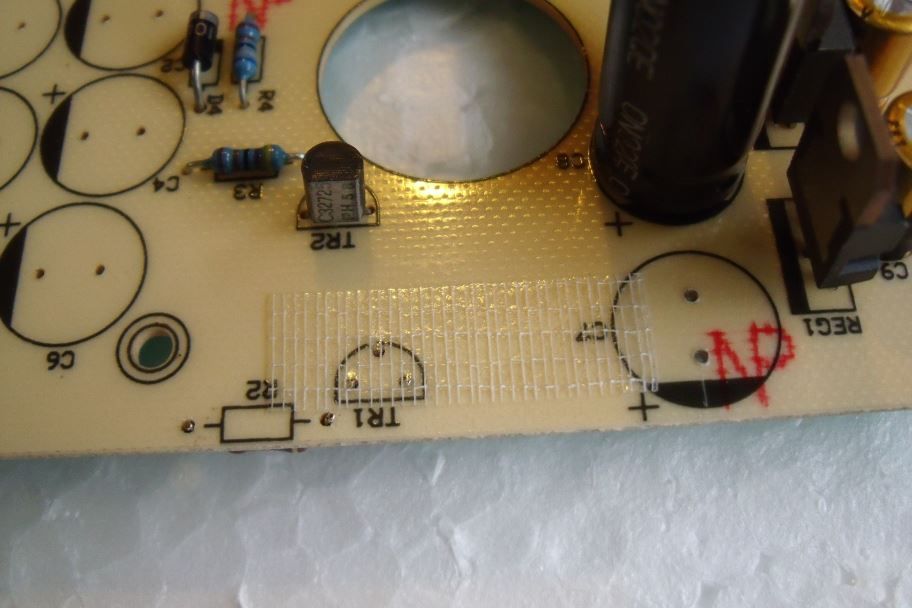 And stick the cap onto the board (bend and fit legs through holes at the same time) : 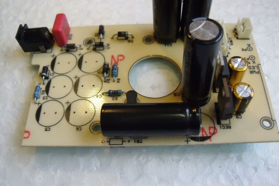 Voila! one neatly mounted cap..... the rest of the Pana FR 1800uF fit perfectly! OK, from the beginning on the PSU board. Here is what it looks like as stock: 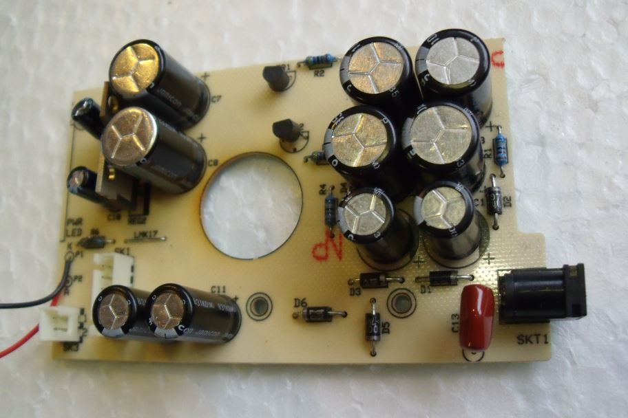 OK, strip all that crap off the board (caps and diodes) and it will look like this: 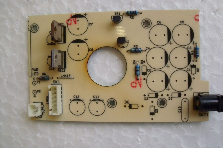 Start off by fitting the UF4001, ultrafast, diodes:  Then fit the polyester cap (I have fitted a WIMA 1uF here): 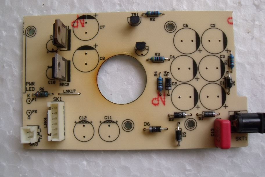 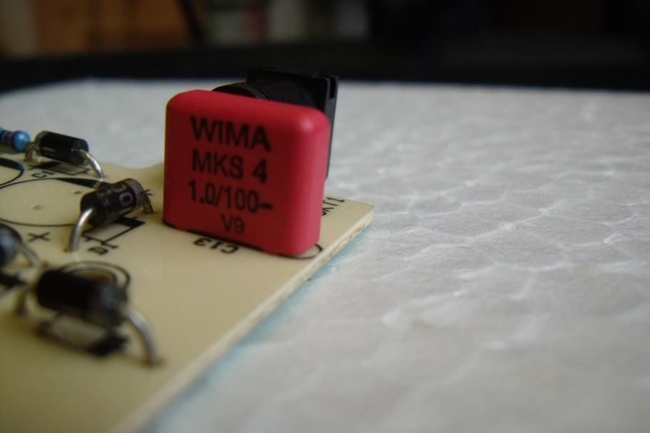 Next, fit the 100uF next to the regulators. I have fitted 135C Samwha VA series here as the regulators get hot... it is not advisable to fit 85C types here: 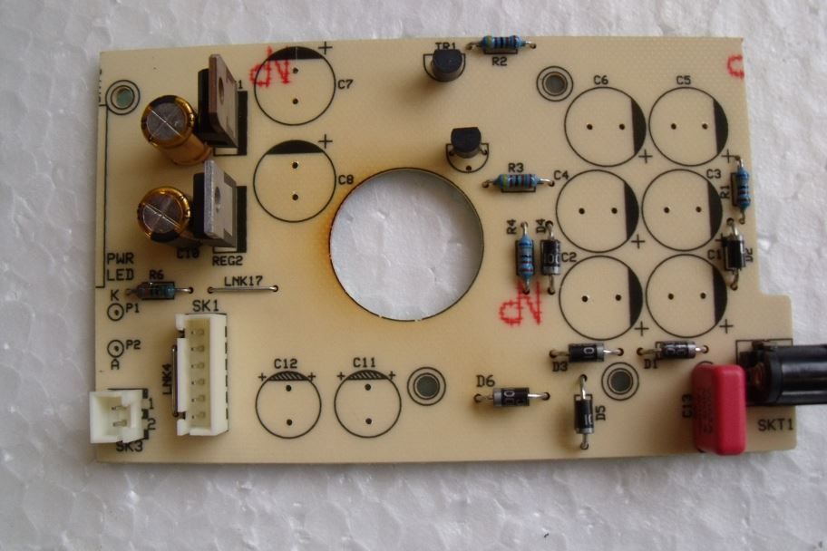 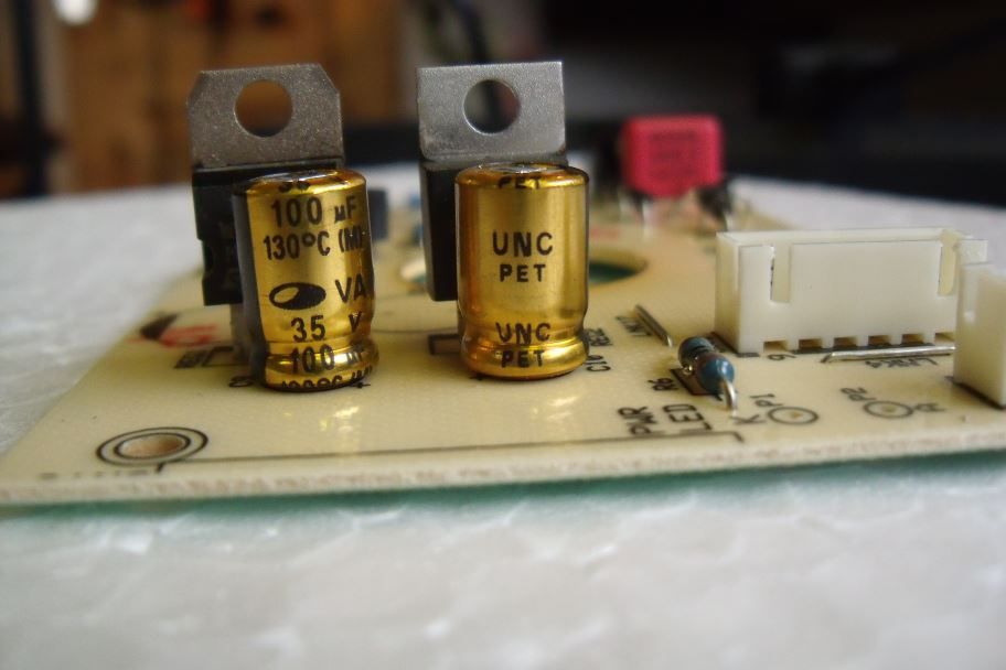 Now all that's required to complete the PSU board is fitting all of the Panasonic FR 1800uF (remembering about the flush mounted one I mentioned above): 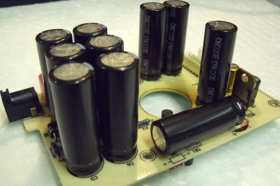 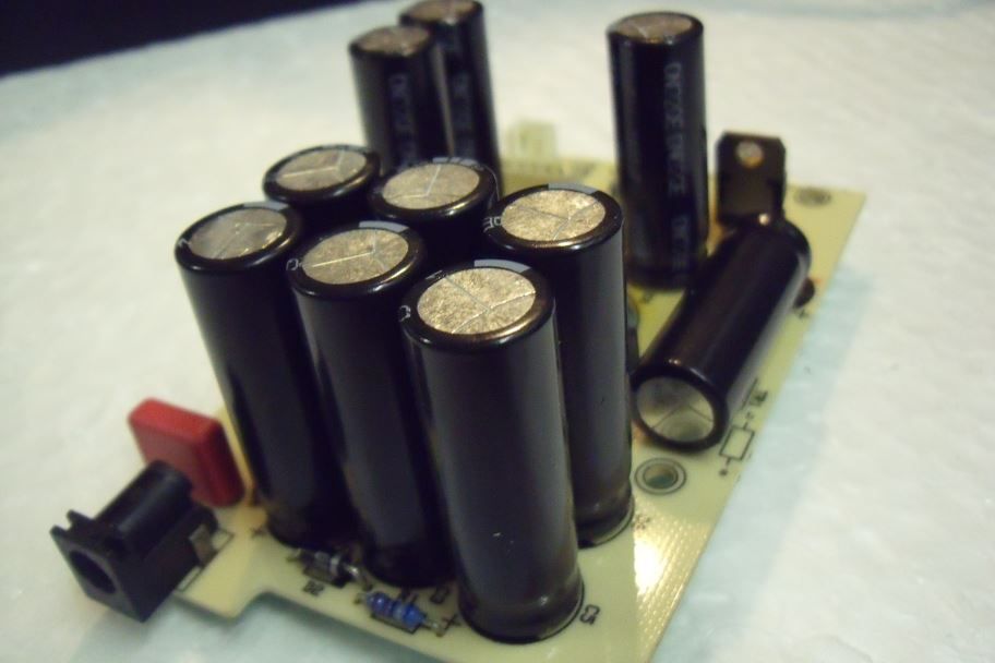 Time to do the bottom board. I had already fitted a new ALPS pot and a Jalco socket but here is the rest of the stock board ready to be stripped: 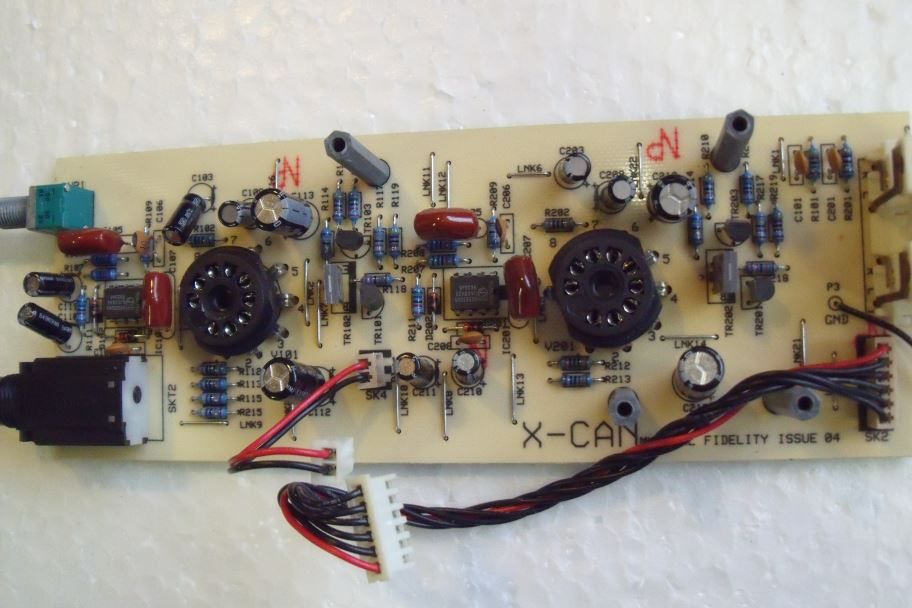 Stripped: 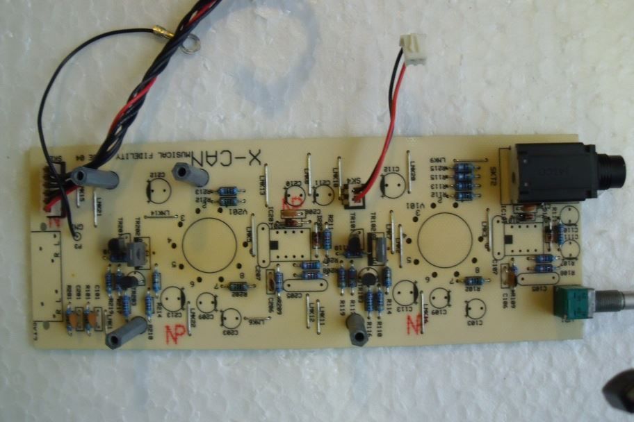 Let's start by fitting the turned pin dip8 sockets: 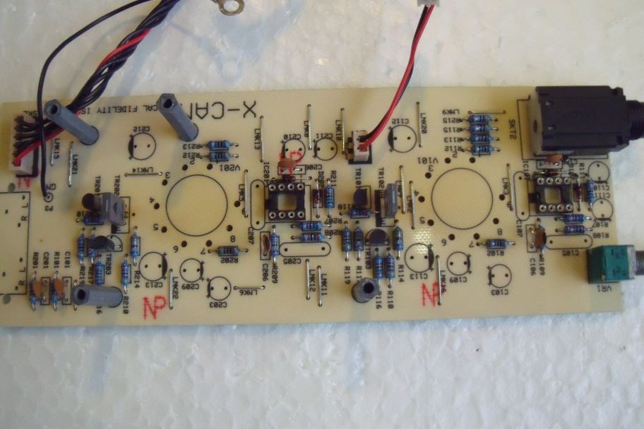 Next we add 4 x 1uF WIMA (MKS4) film caps: 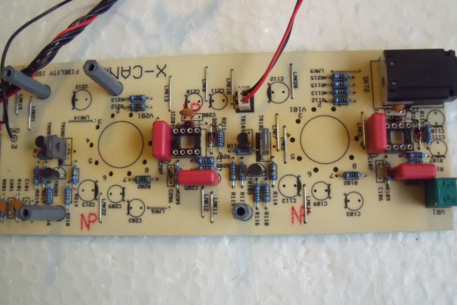 Throw in a couple of nice tasty ceramic valve bases:  Add in a sprinking of caps (10uF MUSE non polars and 100uF Pansonic FM): 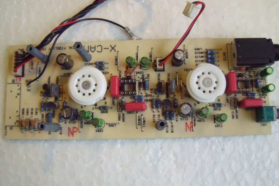 Give it a nice gold tail (new gold plated quad phono socket) : 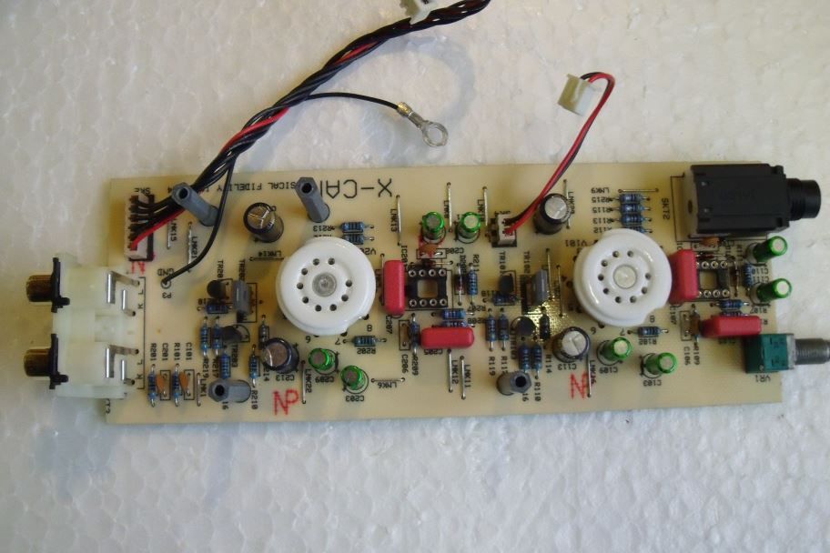 Gently roll in in a couple of nice Burr Brown OPA2227 opamps: 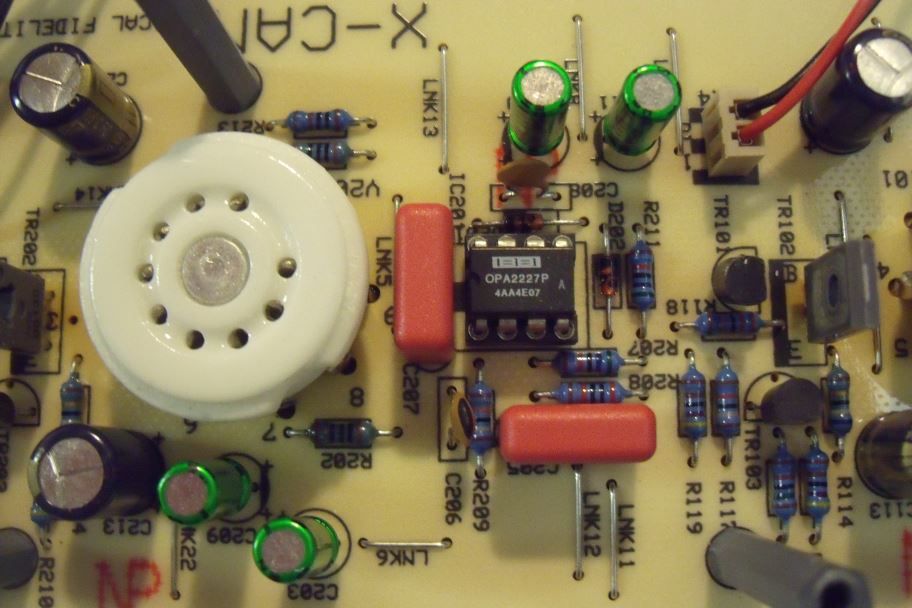 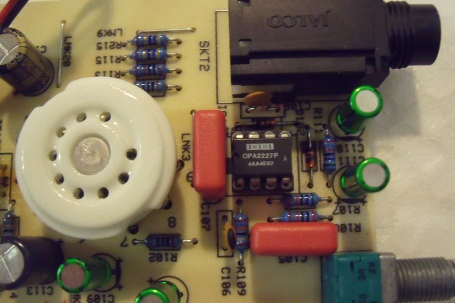 And finish off with an eargasmic pair of NOS 6N23P-EB valves:  Fit the PSU and mainboard back together and admire your work: 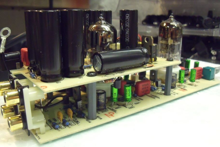 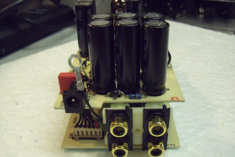 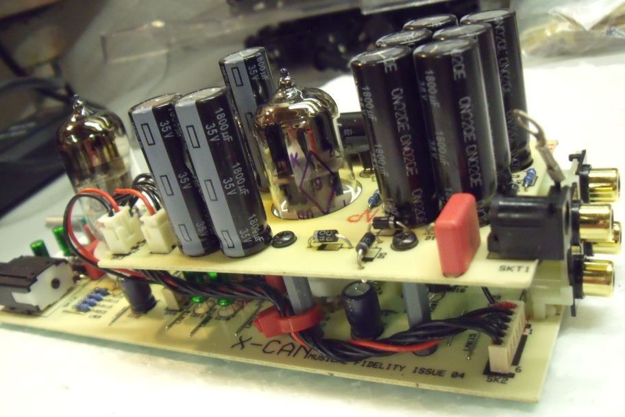 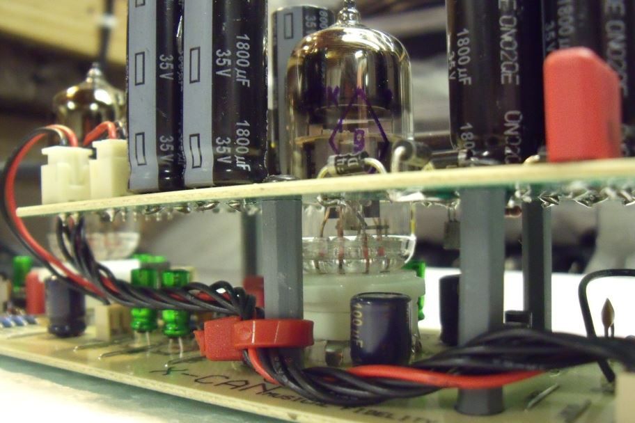 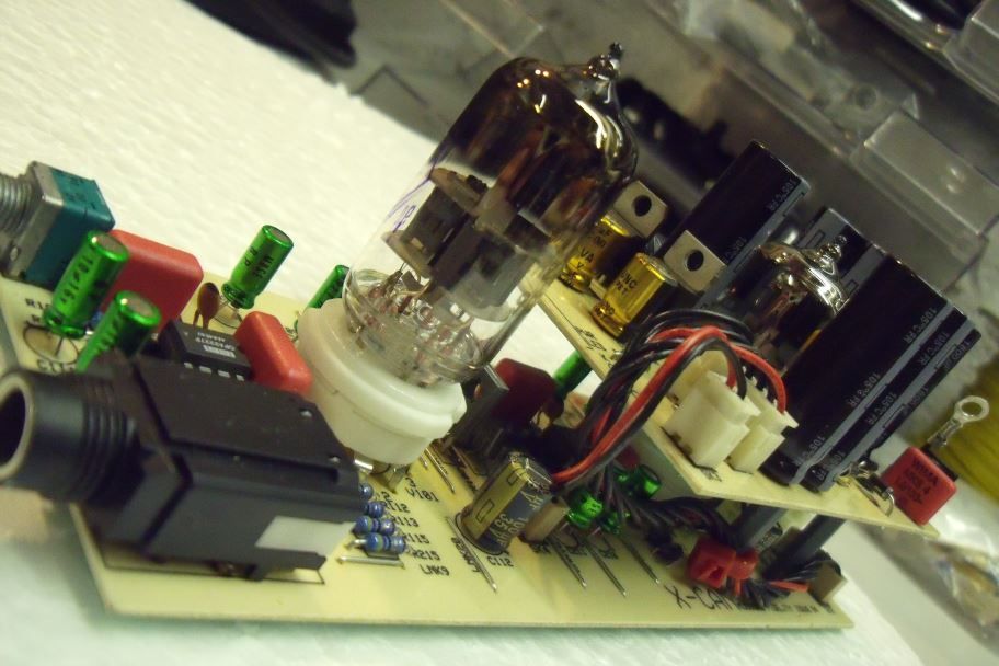 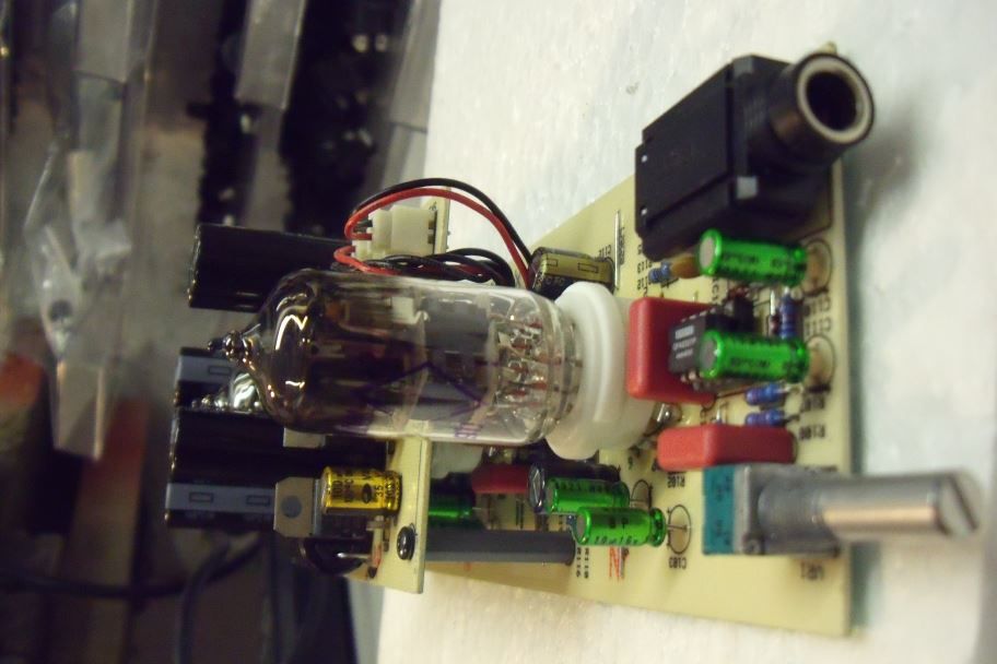 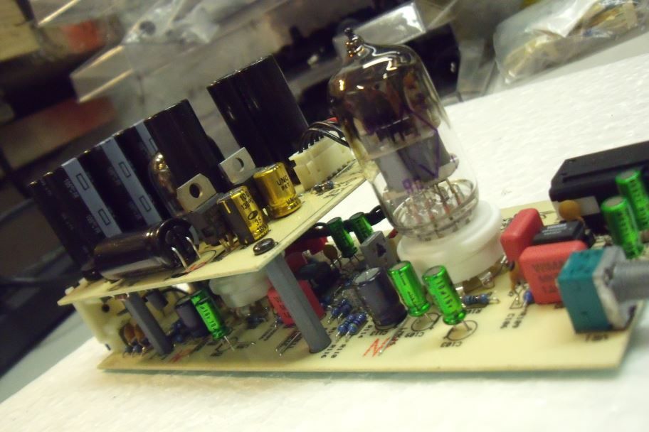 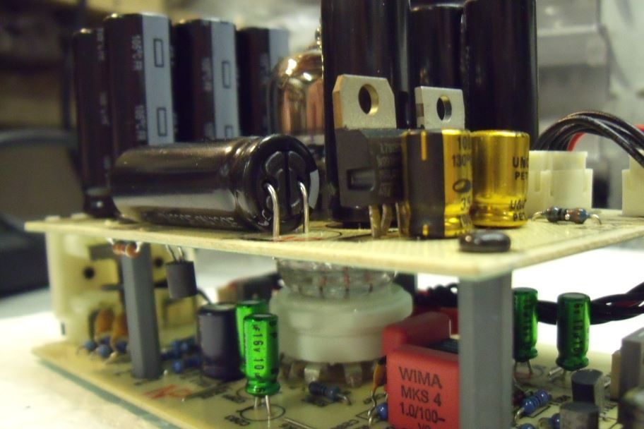 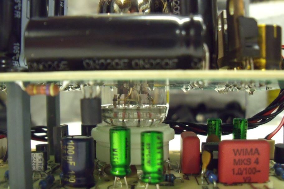 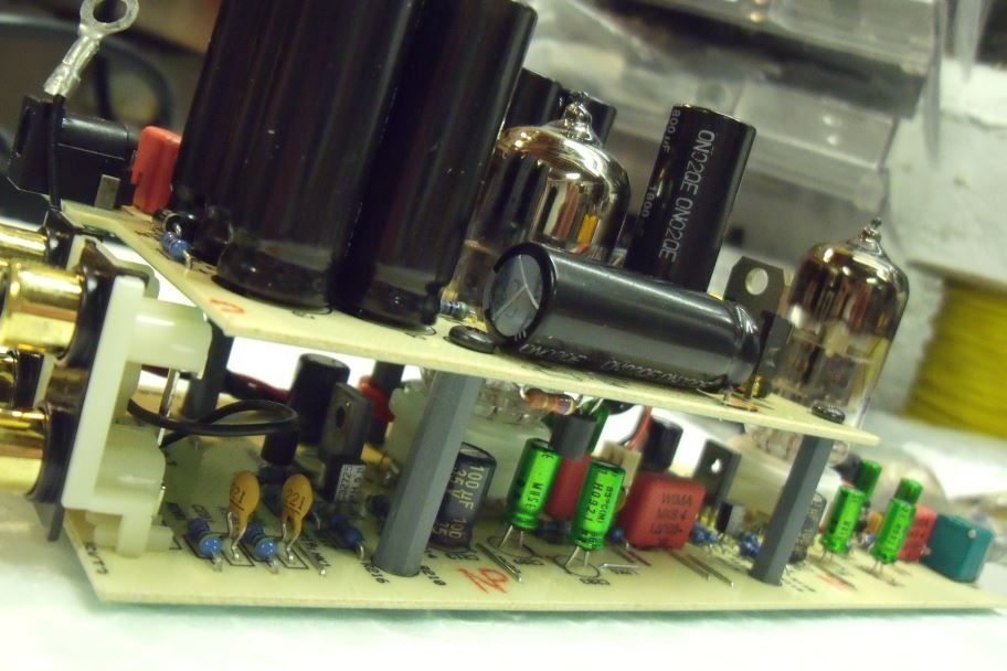 Oh yes....... very sexy  Question is....... does she work? Turn her on and have a look: Houston..... we got a hot one!  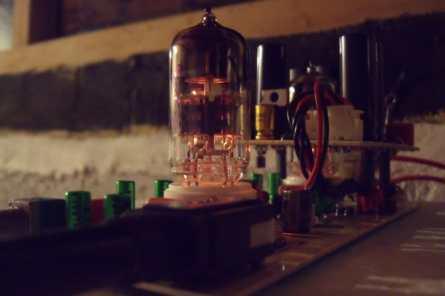 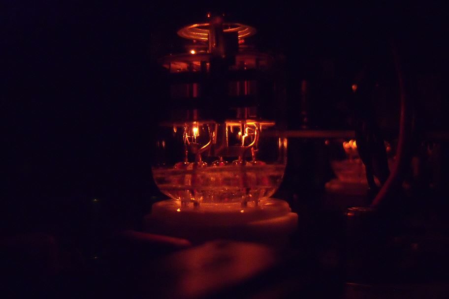 Sooooooooooo..... there you have it, as easy as pie  Here's two I made earlier (a V1 and a V2) Night night children  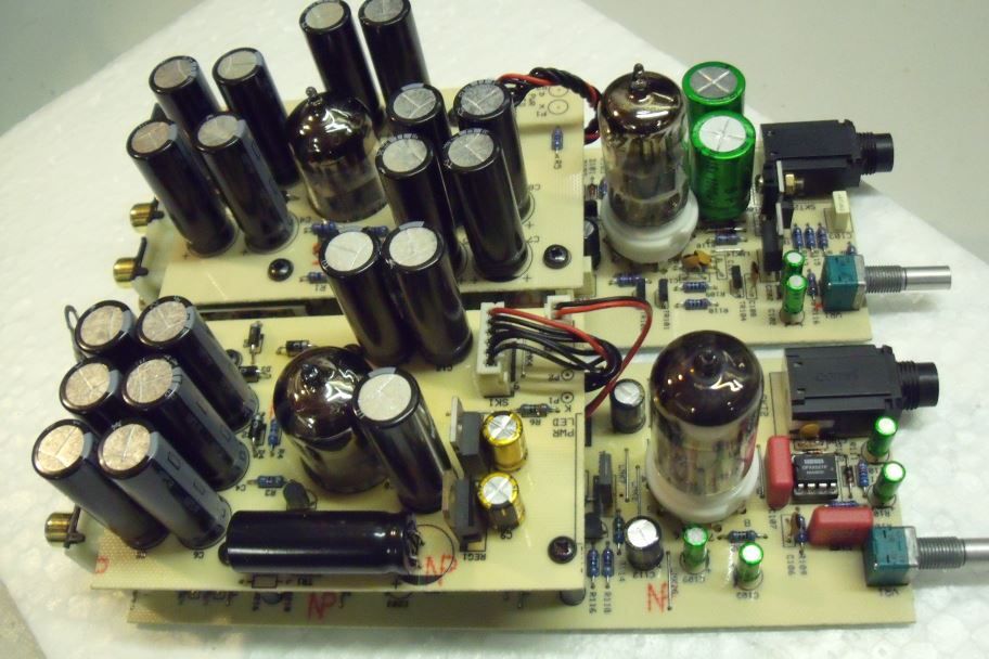 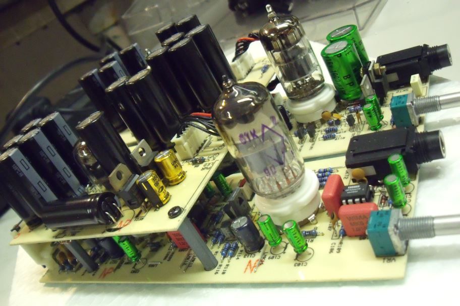 |
|
Deleted
Deleted Member
Posts: 0
|
Post by Deleted on Feb 10, 2011 21:11:13 GMT
Thanks for those fantastic pics (I think you should put a sticky with a step-by-step guide for each X-Cans version)
|
|
|
|
Post by PinkFloyd on Feb 11, 2011 10:13:41 GMT
Thanks for those fantastic pics (I think you should put a sticky with a step-by-step guide for each X-Cans version) There are a few here somewhere gathering dust and it would be faster to just do new guides and "sticky" them as you suggest  Let me just write this down so I can copy it into the X-CANS guide when I do it...... I have a head like a sieve! Javier was a bit concerned that I was using only 16V rated capacitors (the 10uF ones) here is why..... The 10uF capacitors. You can use either 16V or 25V types (whatever you have handy)... the max that will ever go through some of them is 14.5V and two of them have 0V (ZERO) volts across them. C111, C110, C211 and C210 all have 14.5V across them. C109 and C209 have 2V across them. C103 and C203 have 0V (ZERO) volts across them. C103 and C203 can be removed (and the pads on the PCB jumpered over with a wire link) if you are certain there is no DC present on the output of your source.... there will be a slight improvement in SQ with these removed from the circuit, they are "bullet proof" caps and there as protection incase there is any DC present on your source output.... most good quality sources do not have DC on their outputs but it always worth checking first before removing these caps. |
|