Deleted
Deleted Member
Posts: 0
|
Post by Deleted on May 13, 2010 22:11:36 GMT
Chaz,
talking about naff postal services, have you received those little feet I sent for your G2?
Ian got his ages ago......
Chris
|
|
Deleted
Deleted Member
Posts: 0
|
Post by Deleted on May 20, 2010 12:55:39 GMT
Here are some photo`s of the caps Mike sent me installed in my G2, the two i have just fitted underneath the pcb, with bias set to 14v, has improved the SQ still further, given more punch to the Bass, and clarity across the whole spectrum to my ear, sounding great with my new 160gb iPod classic,( both have about 15hrs on them now) hooked up to the Senn 250`s. 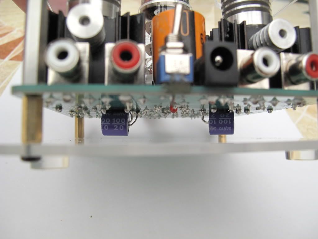 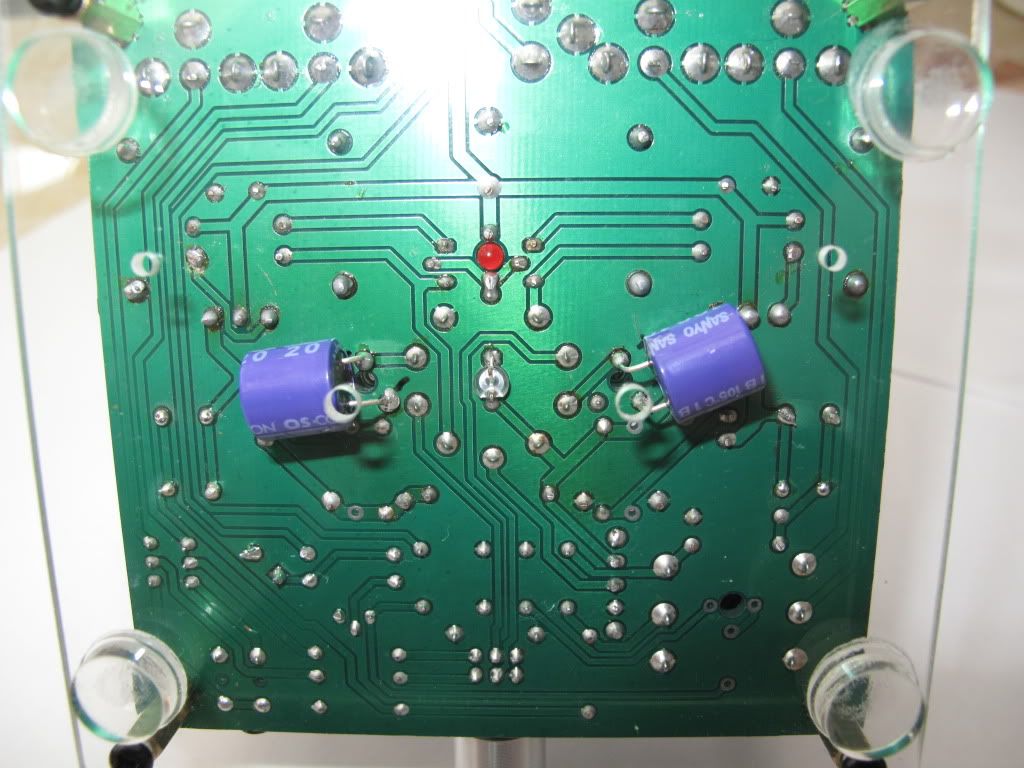 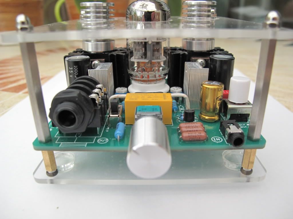 This photo just shows where i have relieved the heat sink of some metal directly behind the right(red) RCA input so that centre pin on my "Chord" connector can not make contact with heat sink again when fully inserted.  A new knob is in the making, the extra ground clearance allowing a larger dia replacement.  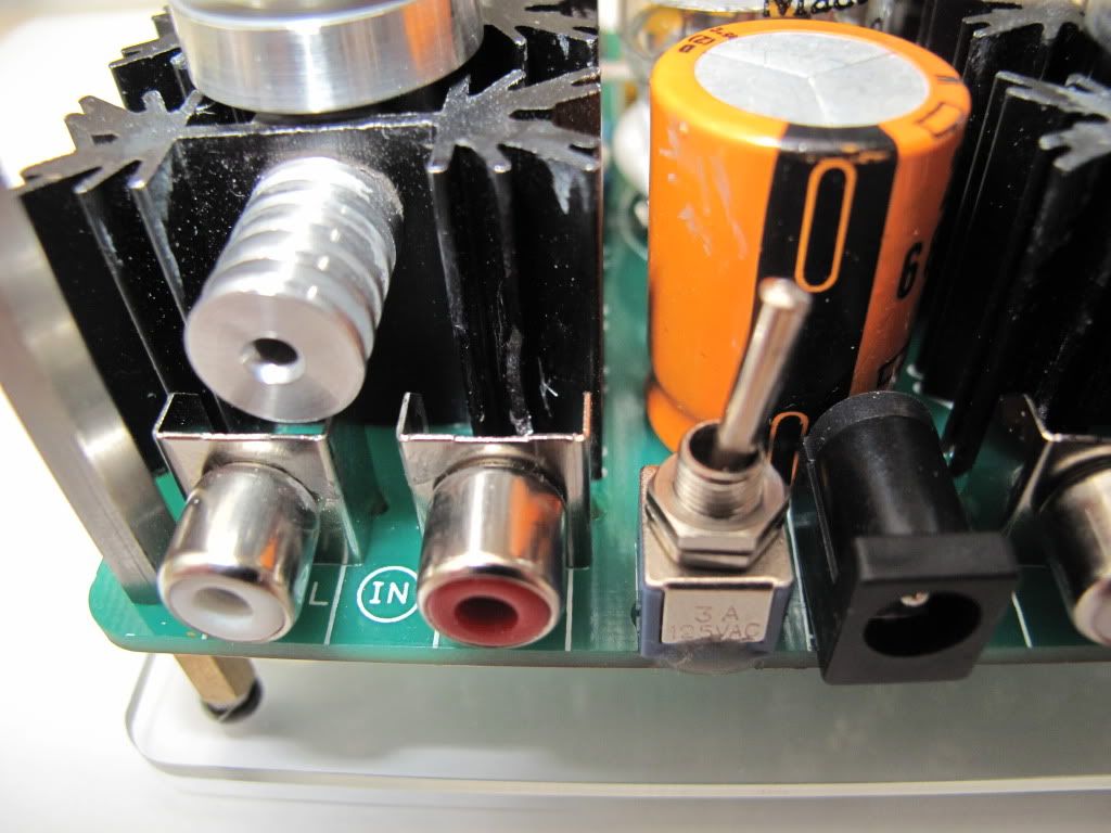 Mick. |
|
Deleted
Deleted Member
Posts: 0
|
Post by Deleted on May 27, 2010 16:57:47 GMT
I have just added a 35v 6800uf 105deg Panasonic Cap to the input, you are a bit restricted in that area, in both Dia (has to fit between heat-sinks 22mm being the maximum available with out touching), also the cap has to be raised to clear PSU socket and components around red LED. I used a 19mm Dia 12mm thick block of Tufnol, drilled to suit Cap terminals, block secured to PCB with s/glue, Cap secured to block with Silicon, and a 24mm hole in top cover, which has been raised from 30-40mm with longer pillars, to open the inside up more. Working well, sounding good  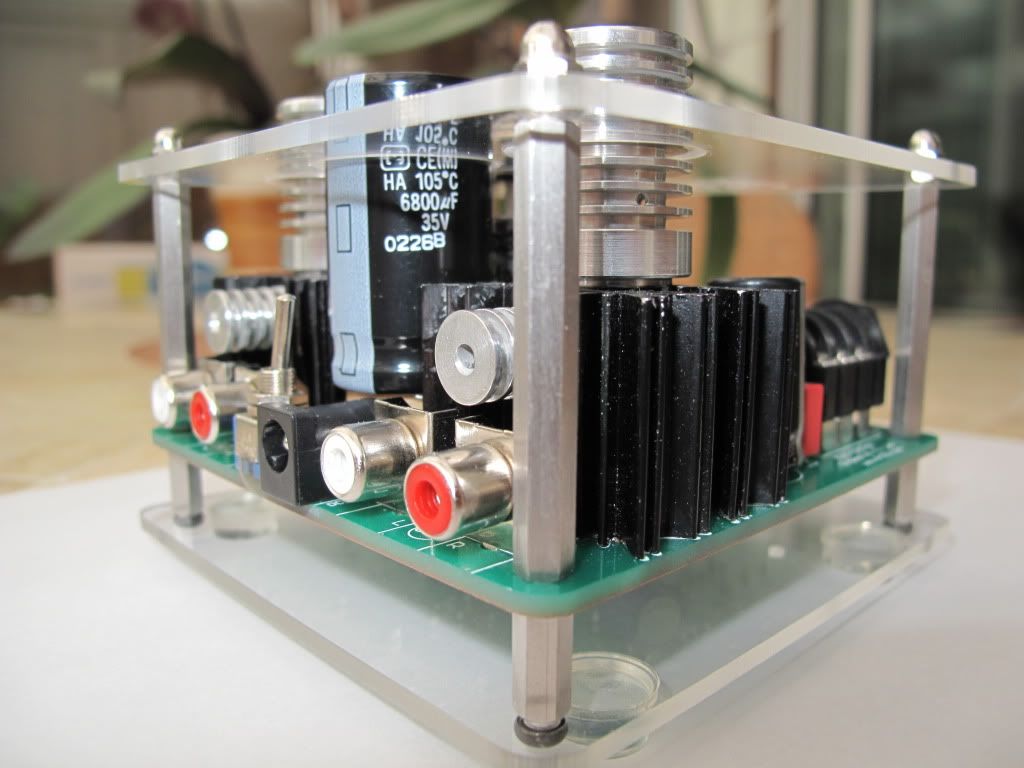 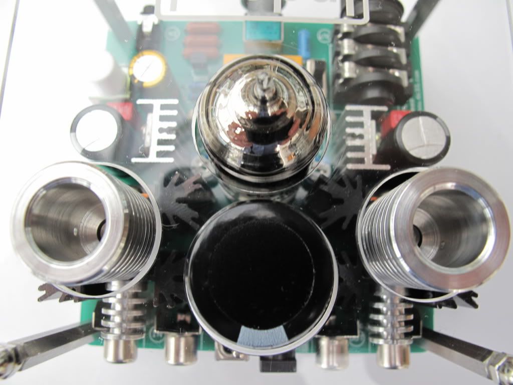 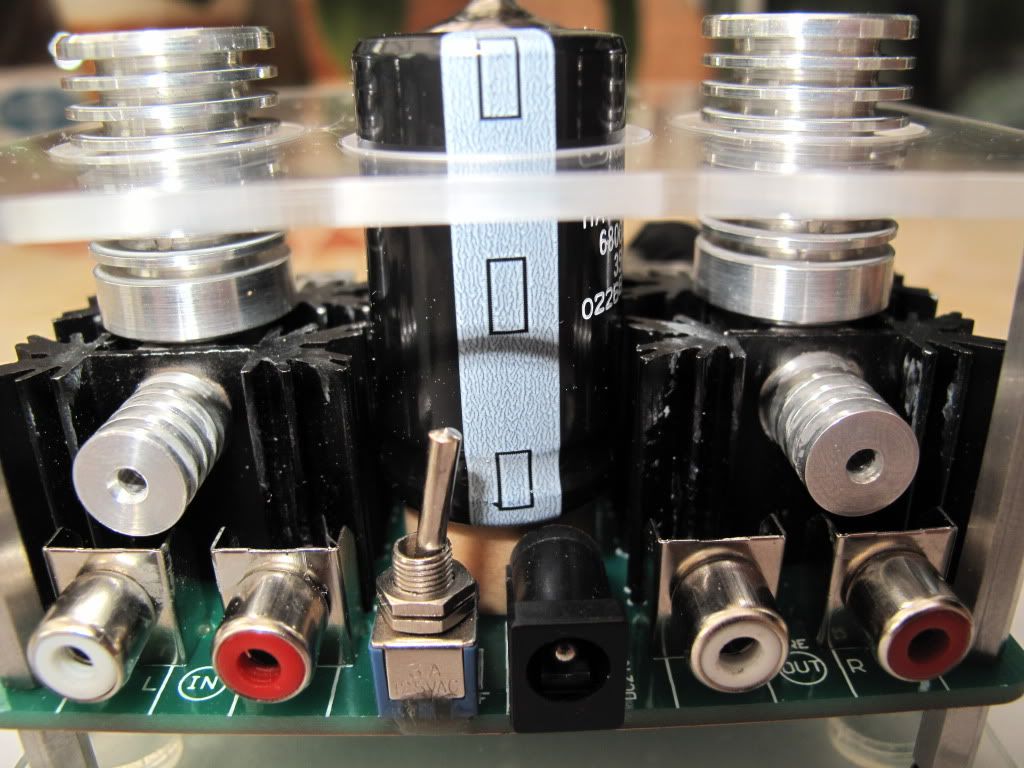 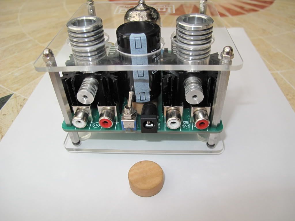 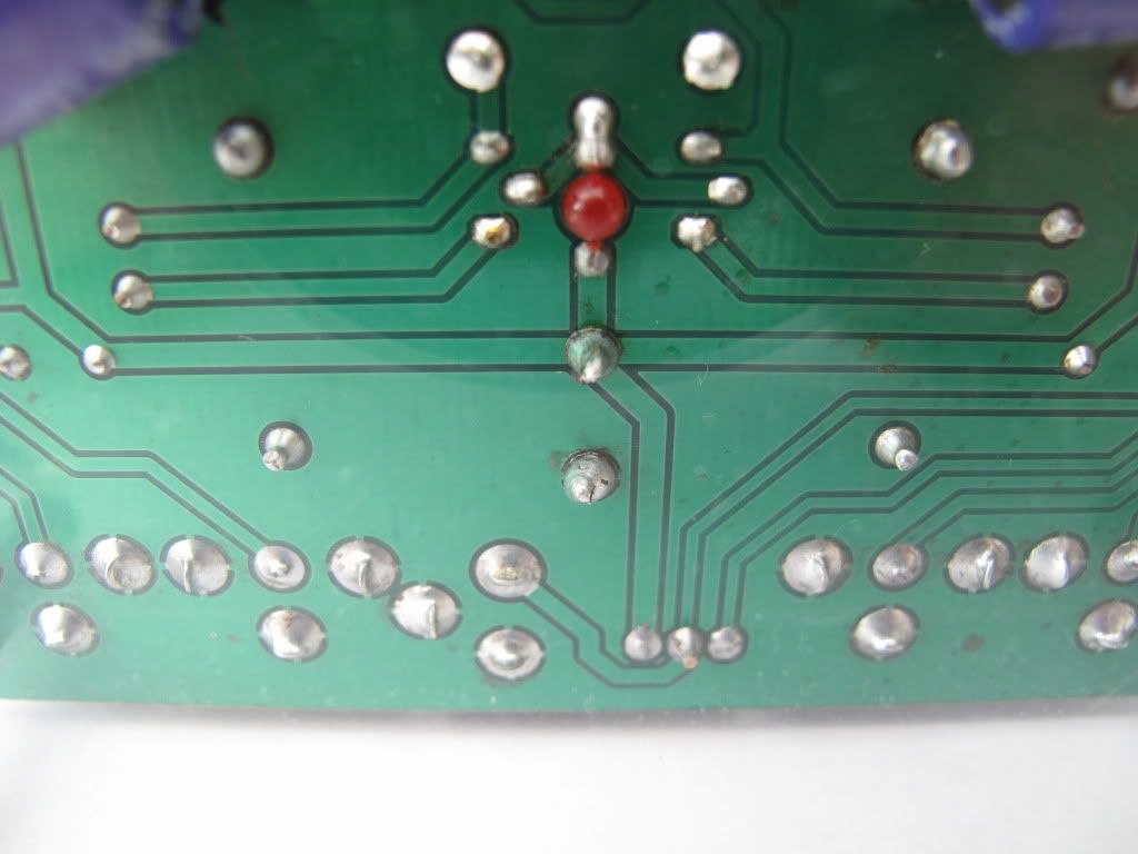 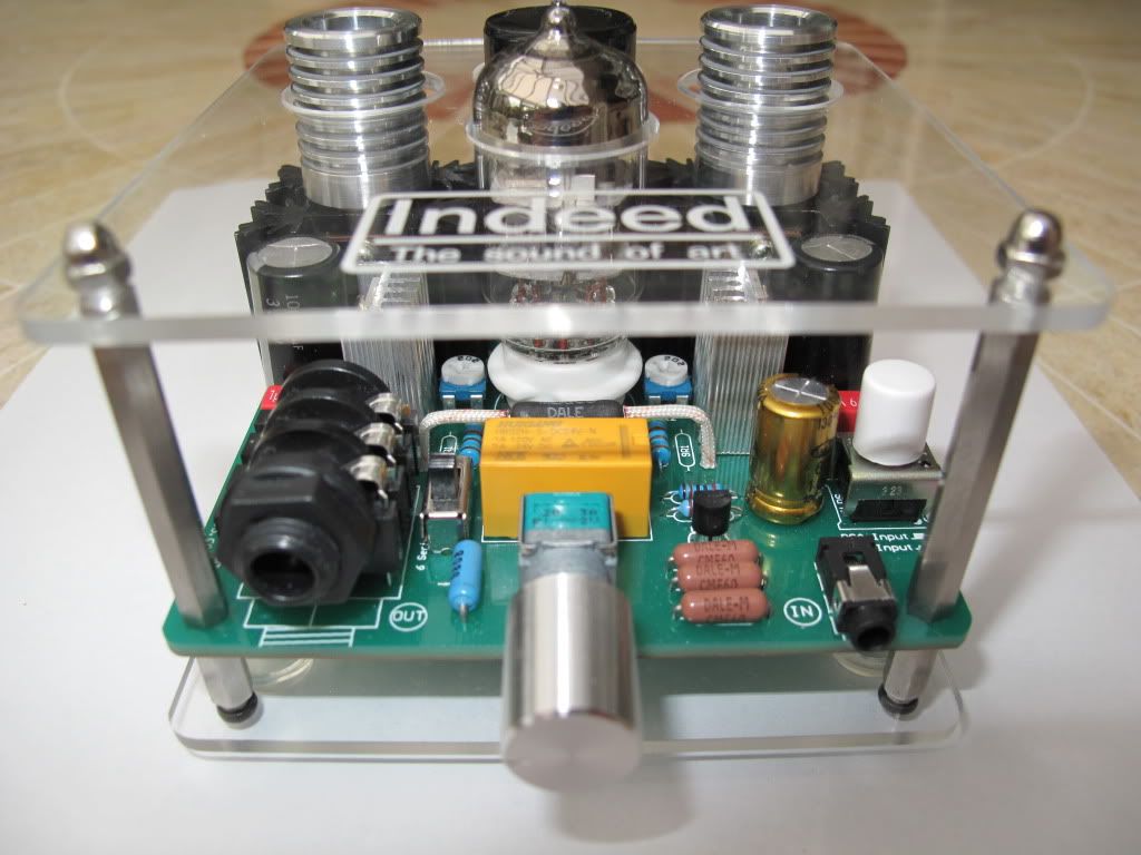 |
|
Deleted
Deleted Member
Posts: 0
|
Post by Deleted on May 29, 2010 16:49:48 GMT
|
|
Deleted
Deleted Member
Posts: 0
|
Post by Deleted on May 29, 2010 18:33:41 GMT
Mick, with those cooling pillars, it's starting to look like the inside of a tardis!! Presumeably, the heat has reduced now with thos bolted on? It looks really good.  |
|
Deleted
Deleted Member
Posts: 0
|
Post by Deleted on May 29, 2010 19:23:47 GMT
Yes Ian,
the more retro the better, sounds pretty damn good though with the upgrade caps installed, in fact just got the 681`s out again been a while since i tried them, hooked them up to the G2, sounds great, nice to have a swap around now and again, proves a point, different is not always better, the two are often confused i think.
Mick.
|
|
|
|
Post by clausdk on May 29, 2010 20:28:27 GMT
Looks gooood Mick
I like the going all out thing..
Now you just need some weels and headlights, then you can take it out in the traffic.
It is an amp. ?? ohhh my bad ;D ;D
|
|
Deleted
Deleted Member
Posts: 0
|
Post by Deleted on May 29, 2010 20:57:30 GMT
A propeller and some wings would suit me better Claus, far less traffic to deal with  |
|
|
|
Post by resetter on May 29, 2010 21:13:40 GMT
Should redo the logo, The Art of Sound. Its looking like an abstract thing you put in the middle of a large piano black table  |
|
Deleted
Deleted Member
Posts: 0
|
Post by Deleted on May 30, 2010 9:13:29 GMT
Should redo the logo, The Art of Sound. Its looking like an abstract thing you put in the middle of a large piano black table  Not far out on that, stands on a small piano black table when not in use, all my design changes have made functional improvements, mostly with regards to cooling. |
|
|
|
Post by Judge Buff on Jun 1, 2010 0:48:48 GMT
Indeed is now shipping the G2 with IRF510s as of 28 May.
|
|
Deleted
Deleted Member
Posts: 0
|
Post by Deleted on Jun 3, 2010 8:07:24 GMT
Can someone that owns a G2 post pictures of the G2 from above, i.e. component side (top plate off preferably) and the bottom of the PCB (the PCB copper traces) I can draw/post the schematics for this amp in this case.  I might bother the poster with some questions regarding the writing on some parts (values/part numbers) afterwards..  |
|
|
|
Post by clausdk on Jun 3, 2010 8:45:38 GMT
Can someone that owns a G2 post pictures of the G2 from above, i.e. component side (top plate off preferably) and the bottom of the PCB (the PCB copper traces) I can draw/post the schematics for this amp in this case.  I might bother the poster with some questions regarding the writing on some parts (values/part numbers) afterwards..  You can borrow mine if you wish and if you feel like making it better be my guest   |
|
Deleted
Deleted Member
Posts: 0
|
Post by Deleted on Jun 3, 2010 10:31:57 GMT
For now I only need 2 pictures to extract the schematics.
the higher res the better.
If you are willing you can mail me the 2 pictures.
At this moment time is very limited for me.
|
|
Deleted
Deleted Member
Posts: 0
|
Post by Deleted on Jun 3, 2010 11:54:59 GMT
Frans,
underside only sent.
|
|
Deleted
Deleted Member
Posts: 0
|
Post by Deleted on Jun 3, 2010 13:36:38 GMT
The basic schematic of the G2 is the same as the earlier versions. There are few differences though. 1: being obvious, ground-plane instead of ground-wires. 2: the 3.5 input and line in are now switched so you can attach 2 different sources at the same time and switch between them. Alas now you can't use the 3.5 socket for input and line-in as throughput but who cares. 3; Another improvement being the power switch, better quality. 4: The relay that is to prevent pop on switch at power up by making a delayed relay 'free' the outputs after a period of time. I say is to because as it is designed it only seems to have this function when the powersupply is already on (for at least a few seconds) and the amp is switched on later using the power switch on the amp itself. When you power-on the amp with the powerswitch already in the 'on' position by inserting the SMPS into the wall socket the delayed action relay does not do anything (you can still hear the on 'pop') 5: another (big) improvement being able to roll more tubes by adding the 6-12V switch. Since the output relay is NOT in the audiopath (it only shorts the output to ground at power-up) this cannot affect the sound. What's different in the sound-path are 3 things. 1: They added a 100nF bypass cap in parallel to the 1000uF output cap. 2: They increased the class A current from 160mA to 280mA (almost doubled it) Now it get's even hotter (hence the extra cooling) and it can drive lower impedances easier. 3: Output resistor has changed from 47 Ohms to 30 Ohms. (influences the EQ/SQ) The extra current compared to the earlier versions is dissipated into even more heat by the 2 big resistors next to the tube. Funny thing being... they designed the board to have a LED shine through the HP out socket as soon as the relay 'frees' the output. The LED can't shine very bright due to how it was designed so it is left out probably for that reason. I doubt it would be clearly visible anyway unless they intended to use another HP socket. The thought was fun though. Schematics:  |
|
Deleted
Deleted Member
Posts: 0
|
Post by Deleted on Jun 16, 2010 19:36:59 GMT
The G2 is modded and has become unrecognizable.. Specs (frequency range e.t.c.) are similar to the modded Miridiy (see pdf in Bravo Indeed thread) Only the class-A current is higher and output resistance is 30 Ohms instead of 47 Ohms. I don't care for the blue led so changed it for orange, it appears to me more red though. It has better cooling (40oC) and I don't like the see through from the front so put a grill in front of it.   Schematics:  |
|
|
|
Post by PinkFloyd on Jun 16, 2010 20:08:31 GMT
Holy crap frans..... it looks like it's going to take flight!  Nice work man, it certainly looks "different"  Panasonic NHG coupling caps? I've got a thousand of those puppies (1000uF / 35V) so can recognise them quite easily  Good to see you are having fun with it, the schematic looks superb too. All the best, Mike. |
|
|
|
Post by Judge Buff on Jun 16, 2010 20:55:53 GMT
Frans, that is a great looking piece of electronic derring-do! Are those cathode bias caps on the pots? With the HS revamping, you've opened up the entire board! I'm going down under like leo did and I'm buying standoffs for down below and topside.
Gents, when I broke-out my electronic calipers to measure the threads/diameter, the battery was dead. I had to use the low-tech scale on the side and I don't trust it. According to it, the threads are 2.5mm and the "column" is 4mm. Can anyone take a quick measure for me? I'd appreciate it.
Regards,
Buff
|
|
|
|
Post by PinkFloyd on Jun 16, 2010 21:12:38 GMT
Whatever they are on the pots they are deffo Panasonic FC types (I can tell just by looking at them)..... my preferred value would be in the region of 100uF to 470uF with 220uF being my value of choice in this application. Frans will, no doubt, explain all when he publishes his "modded" version of the schematic....... The Chinese manufacturers (indeed / Bravo / Miridy) are watching this thread closely..... I just hope, when they introduce the "MKlll" that they give all the guys at Rock Grotto (Particularly Frans) some credit...... we have done a full frontal on this amp (free of charge) and the best brains in Europe have come together to get the best out of this design..... Helliharis, Frans, Leo and all the other guys.... a big thanks for your efforts  Mike. |
|
Deleted
Deleted Member
Posts: 0
|
Post by Deleted on Jun 17, 2010 8:14:56 GMT
I went down under too (with posts = M3 thread)
On the bottom of the PCB the heater's power supply is mounted directly below/onto the power capacitor.
The caps are Panasonic 470uF/10V types and are in parallel to the pots.
The coupling caps are Panasonic 2,200uF/25V/105oC types
The power cap is replaced by Mike's 1,000uF/35V/105oC Nichicon cap
I really don't like high temperatures and the LM317 desperately need more cooling when IRL's are fitted.
|
|
Deleted
Deleted Member
Posts: 0
|
Post by Deleted on Jun 19, 2010 8:47:37 GMT
|
|
Deleted
Deleted Member
Posts: 0
|
Post by Deleted on Jun 21, 2010 17:08:08 GMT
Cheers Frans,
Good detailed work/instructions there. I look forward to getting mine fired up again so I can tinker.
|
|
Deleted
Deleted Member
Posts: 0
|
Post by Deleted on Jun 21, 2010 19:25:10 GMT
even more detailed now.  I have elaborated on the heater power supply part so It will be easier to do. Just download the pdf again ...  |
|
Deleted
Deleted Member
Posts: 0
|
Post by Deleted on Jun 26, 2010 12:40:29 GMT
My new SMPS arrived yesterday and all is well  I can now have a serious look as Frans' mods and see how far I can take it. Regarding which.... Frans, do you think the case I've used would be sufficient heat sinking, via small aluminium billets, if I was to go the whole hog? as posted hereIncidentally, I earthed the casework to the board like Frans suggested, with my mobile phone on the same small table there is no interference at all  I'm also still looking for a cost effectiveway of putting a linear psu together, any thoughts? |
|