|
|
Post by PinkFloyd on Mar 22, 2007 10:38:19 GMT
|
|
|
|
Post by PinkFloyd on Mar 22, 2007 10:41:53 GMT
And here they are! Extreme Modifications to the Musical fidelity X-DAC V3. By Alex Kethel (forum member sandyK)Part 1 These modifications will take the sound quality of the X-DAC V3 up to, or better than, the sound from respected DVD players such as the Marantz SA-11. WARNING : Do not attempt these modifications unless you are an advanced hobbyist, or have a professional repairer perform them for you. The X-DAC V3 has very fine copper tracks and may be severely damaged if you are not experienced in these areas. Using the optional Musical Fidelity power supply instead of the supplied plugback, will make a worthwhile improvement to the X-DAC V3, The X-DAC V3 does not have any voltage regulators supplying the analogue section. A substantial improvement may be made by feeding the X-DAC V3 with well regulated + and - 15V DC from an outboard power supply. STAGE 1. A 30 or 50VA Toroidal transformer with 15-0-15V AC windings may be used to feed a regulated power supply PCB using LM317 and LM337 voltage regulators. Silicon Chip magazine has designed a suitable power supply PCB. 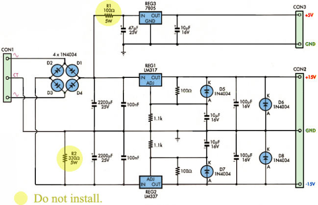 Diagram 1 Jaycar Electronics stocks this kit for AU$17.95 as cat.KC5418 (diagram 1) Other suppliers will also have suitable modules available. Build the toroidal transformer, Regulator supply PCB and other components into a suitable enclosure. 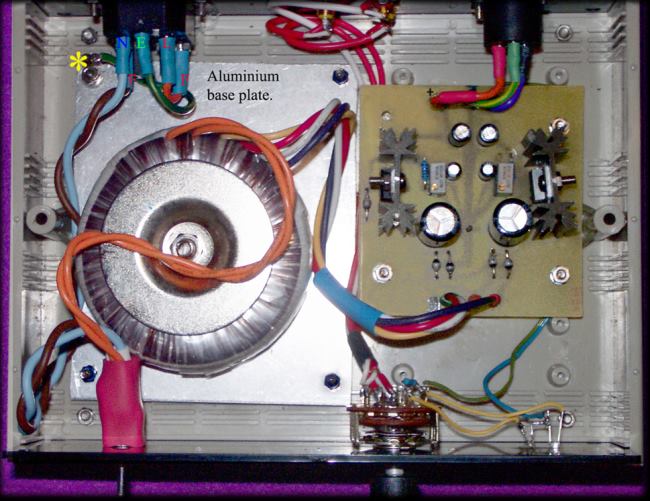 Diagram 2 A male IEC chassis mounting fused mains socket should be used.Install a M205 500mA rated fuse. Make a suitable power supply lead with a 3 pin DIN plug fitted at the X-DAC end. The 0 Volts from the power supply connects to the center pin of the 3 pin DIN plug. Ensure that this plug's + and -15VDC polarities match the X-DAC 's PCB polarity markings. This is essential if the X-DAC bridge rectifier is removed and bypassed. The X-DAC V3 will perform better with this DC power supply than with the optional Musical Fidelity power supply, and may be used without modifying the X-DAC.. STAGE 2. Remove the circular bridge rectifier near the front panel and connect 2 wire links straight across where the bridge rectifier was previously. Double check with a Digital Volt Meter that the +VE marking for the bridge rectifier on the X-DAC PCB , will connect to the +VE supply from the DIN plug when inserted. The -VE supply from the DIN plug should also connect to the X-DAC PCB's -VE marking via the other fitted link. Remove the 2 x 2,200uF capacitors which are connected to the PCB traces from the bridge rectifier . Replace with 2 x 100uF 25V electrolytic capacitors.Ensure that the marked polarities of the new capacitors match the markings on the X-DAC PCB. Be very careful when replacing these capacitors, as they are glued to the PCB. Carefully remove the goo first ! The X-DAC will now have a full + and -15V regulated supply feeding the analogue section.There should be a further improvement in the perceived sound quality from the X-DAC. Attached is a photo of my Regulated power supply (diagram 2). The selector switch is used to switch 2 SPDIF sources, and is not needed for this application.Note that ALL mains wiring, and the mains ON/OFF toggle switch is covered by heatshrink tubing for safety reasons.Mains earth from the IEC socket is connected to the aluminium base plate. IEC Fused Mains sockets vary in their number of connections and pin assignment. A single pole mains switch could also be used.- connect one side of the transformer primary winding direct to the N terminal of the mains socket. The other side of the primary winding still goes to the switch contact.The other switch contact is connected to the fused side of the mains socket. All mains wiring must be in accordance with local standards. END -Part 1. (Part 2 will cover analogue I.C. replacement, as well as other component changes/additions.) DISCLAIMER. This information is given to stimulate interest in upgrading X-DAC V3. The author accepts no responsibility for any damage to equipment, or any injury or death, resulting from these suggested modifications. |
|
|
|
Post by PinkFloyd on Mar 22, 2007 10:45:37 GMT
Extreme Modifications to the Musical fidelity X-DAC V3. By Alex Kethel (Rock Grotto forum member sandyK) Part 2 These modifications will take the sound quality of the X-DAC V3 up to, or better than, the sound from respected DVD players such as the Marantz SA-11. WARNING : Do not attempt these modifications unless you are an advanced hobbyist, or have a professional repairer perform them for you. The X-DAC V3 has very fine copper tracks and may be severely damaged if you are not experienced in these areas. STAGE 3. 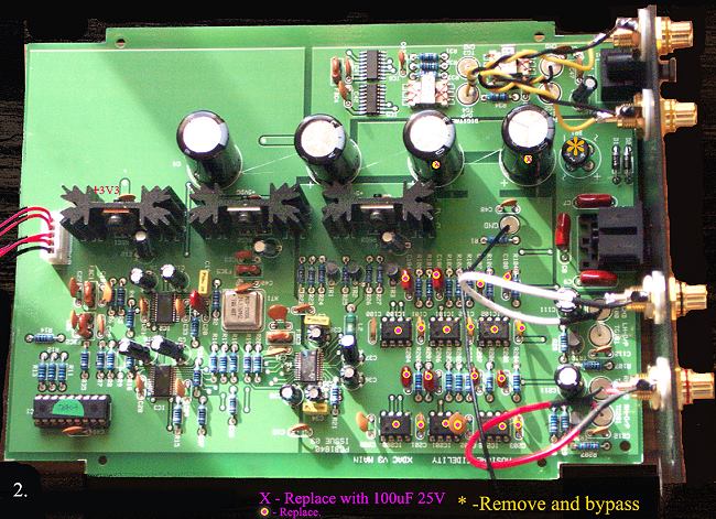 All components marked are replaced. The NE5532 I.Cs are replaced by OPA2134. The 100nF ceramic bypass capacitors (close to the I.C.s) are replaced by normal 100nF 63V polyester types. Do not replace the 2 ceramic bypass capacitors that are not marked. Other polyester capacitors around the NE5532s are replaced by polypropylene types of the same value if obtainable. The circular bridge rectifier near the front panel is removed, and 2 wire links fitted. 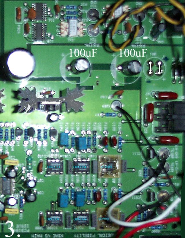 Photo 3 Be very careful removing these components, as the PCB is double sided, and many of the tracks around the I.Cs are very thin and easily broken.If in doubt, get an experienced person with the appropiate equipment to replace these components !After replacement, check the PCB carefully with a magnifying glass for any dry joints, or short circuits between tracks etc. Check that the OPA2134 supply pin voltages are correct.(pin 8 = +15v, pin 4 = -15V - Pins1 and 7 should have low voltage readings ! ) If everything appears to be O.K. , audition the X-DAC again. There should be a further noticeable improvement in soundstage and resolution. STAGE 4. To obtain maximum resolution, fit AD8066 SOIC modules in place of the output OPA2134 I.C.s SEE PHOTO 3. (again) Before fitting the AD8066 modules, the supply rails must be reduced to + and -12V. 78L12 and 79L12 voltage regulators are fitted under the PCB as shown: 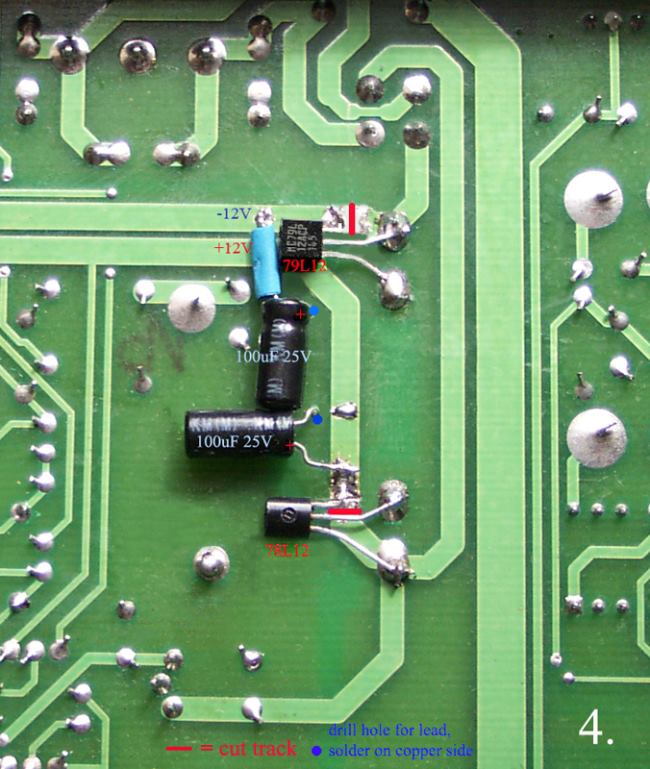 The AD8066 should now be completely stable WITHOUT the need to fit ceramic 100nF capacitors adjacent to the supply pins. The conventional wisdom of fitting ceramic capacitors at this location when using these devices will cause a "hardening" of the sound. Carefully check all work again as previously, and ensure that the supply pin voltages of the AD8066 are + and -12V. The output pins that connect to the output coupling capacitors should read only several millivolts. If all work has been performed correctly, the X-DAC V3 should now sound vastly improved, compared with the unmodified version. If the DC Out is a couple of mV or less, the capacitors C111 and C211 may be bypassed with a wire link. I suggest that if connecting a DVD player with a switchmode power supply to the X-DAC V3, that the 4 high voltage diodes in a bridge rectifier configuration (e.g. 1N4007 etc) near the mains input lead ,and connecting to the large high voltage electrolytic capacitor, be replaced by Vishay BYV26C (600V) diodes , which are fast, slow recovery types. These diodes are available on order from RS Components. They work out at about 31 cents each (AU) when 50 purchased. Approx. 1 month delivery time is average. Fit a 100nF 630V polyester capacitor across this electrolytic capacitor. Sticking adhesive sound deadening foam inside the cover, but not directly over the transport mechanism when the cover is back on, as well as under the chassis to reduce vibration, will also help. ONLY DO THESE MODIFICATIONS IF YOU ARE AN EXPERIENCED CONSTRUCTOR ! LETHAL VOLTAGES EXIST IN THIS AREA!!The result is normally cleaner sounding audio, and a glossier, more 3 dimensional picture. Replacing the diodes, and fitting the 100nF 630V capacitor to a DGTEC HD STB,also gave similar improvements to audio and video. These mods were brought to you by forum member sandyK. |
|
Fergus
100+
Done a David Ike and is now known as Godkin 
Posts: 197
|
Post by Fergus on Mar 22, 2007 17:13:11 GMT
You're right to get someone professional to do it, Miguel. As SandyK says, there are very fine copper tracks, especially around the small DAC chips. I simply won't go near these, my soldering abilities are not up to it. I'll look around and see if I can get someone to do it for me, maybe somebody local.
|
|
|
|
Post by ungawa on Mar 23, 2007 2:00:19 GMT
Wow - more upgrade work to mull over... Great Piece, Great Timing!
.. and thanks to Alex - and Mike for posting !!
Replacing the 2 2200uF 35V caps with 2 100uF 25V ones is a curious move - Is that related to the replacement of the op amps to AD8066 SOIC ?? Or can it be done irrespective (as the piece implies...) ?
Gee - once all these multiple mods have been done - this thing is gonna launch rockets !!
Cheers - Brent
|
|
Deleted
Deleted Member
Posts: 0
|
Post by Deleted on Mar 23, 2007 4:26:19 GMT
Ungawa
Voltage regulators are in essence feedback amplifiers. Using large value filter capacitors slows down their response.
Looking at most audio equipment, where a voltage regulator is adjacent to the analogue audio I.C.s, the usual capacitor value is between 10-100uF. The main objective is to create as low an impedance source for the I.C.s as possible , without any major dips or peaks in the supply impedance. Otherwise you will get some audible colouration somewhere in the frequency response. The large value electrolytics are normally at the input to the regulators (digital circuitry too) and the smaller value electrolytics across the output of the regulator are primarily for stability of the regulator.
sandyK
|
|
|
|
Post by PinkFloyd on Mar 23, 2007 11:03:26 GMT
|
|
|
|
Post by ungawa on Mar 24, 2007 1:34:26 GMT
Yes - Sorry Sandyk - I'm pretty new to this, without the experience of circuit modding others here will no doubt have. I agree with Mike that this is an "extreme" mod in that I would be modifying the unit past my usual point of component swap-outs and so on. Did you try many other op-amps before settling on the 8066 ? Thanks again ! - Brent |
|
Deleted
Deleted Member
Posts: 0
|
Post by Deleted on Mar 24, 2007 3:35:59 GMT
Brent
The 8066 was chosen mainly on technical merits such as bandwidth,distortion etc. Many favourable discussion group comments, as well as Soundlabs comments ,were also taken into account. A couple of us have also fitted them to DVD-A /SACD players with good results. I have been fortunate to be able to compare the results against a friends Marantz SA11 as well. I am also using the AD8066 in a modified Silicon Chip designed Headphone amplifier. (Jaycar cat.KC5417) This allows me to get maximum quality from PC headphone audio ( LPCM Music Videos etc.) via a Soundblaster X-FI card. Having them available as complete modules from Soundlabs Group enabled us to evaluate them , before buying larger quantities of the basic I.C. and adaptor boards.
B.T.W. I noticed quite a few comments about the possible removal of the output capacitors in the X-DAC V3. If OPA2134 is used in all 6 locations, the resulting DC output voltage is normally 2 milliVolts or less. This allows the removal, or short circuiting of these capacitors, with a minor audible improvement.
I also mentioned replacing the switchmode bridge rectifier diodes in DVD players,STB etc with Vishay BYV26c diodes. These 600V rated diodes have a reverse recovery time of only 30nS . This is less than half the recovery time of diodes such as the UF4007 (1,000V) which has a recovery time of 75nS. A very favourably reviewed Oppo upsampling DVD player was modded with these recently. There was even a noticeable visual improvement when using HDMI !
SandyK
|
|
Deleted
Deleted Member
Posts: 0
|
Post by Deleted on Apr 1, 2007 21:31:33 GMT
A friend of mine who has just successfully completed the full modifications, reminded me that I had not mentioned C112 and C212 . These are 100pf ceramic capacitors adjacent to the RCA output jacks. I had forgotten to replace these ceramic capacitors with either polypropylene or polystyrene types. Whether to leave the muting circuit intact, or remove it, is more a matter of personal choice. However, I have had a Dolby Digital Decoder, and a VHS HI-FI Recorder ,both develop a problem due to a muting transistor. This affected channel balance.Replacing the transistors in the offending channel rectified the problem.
SandyK
|
|
|
|
Post by ungawa on Apr 29, 2007 3:40:49 GMT
Sandyk
Having been appreciating the swap out part of your upgrade (very much) - I'm getting to the point of wanting to try out the AD8066 Mod you kindly offered up to us ....
I have a couple of questions before ordering some parts .. Is the AD8066 is on a converter of some kind ? Do you have any info on where I could find them ?
Also in pict 4 - Can you further explain the Blue markers - they are points for drilling through the board - and soldering onto the copper on the other side of the board - is that right ?
Cheers - Brent
|
|
|
|
Post by ungawa on Apr 29, 2007 4:26:05 GMT
.... also - I can't find any 79L12 greater than 14V input - are they ok ?
Sorry - Soldering I'm good at - Working out replacement part compatabilities I'm not so good at ......
Cheers - Brent
|
|
Deleted
Deleted Member
Posts: 0
|
Post by Deleted on Apr 29, 2007 9:00:06 GMT
Brent Initially I used AD8066 modules from www.soundlabsgroup.com.auThey cost AU$32 each. Later on, a few of us used the I.C.s on little PCB boards made for us by RCS Radio. Seeing you only need 2, best to get them ready assembled from someone like Soundlabs. The "blue" holes are drilled with a 1mm PCB drill, and the copper around the holes on the top side carefully scraped bare for soldering the capacitor leads. The 78L12 and 79L12 are available from Altronics (and others) These voltage regulators have an absolute maximum input voltage of 35V. Did you use I.C. sockets for the OPA2134 ? I didn't, but a friend did, and he is now able to directly plug in the new, raved about LM4562 . Bummer ! BTW,Digi-Key now has stocks of the SOIC AND DIP8 versions of the LM4562. I ordered a few of both types, but the SOIC version wasn't in stock when they despatched my DIP 8 version. THe SOICs arrived in stock the next day, (26th April) so they sent 2 packages , and I had to pay 2 lots of P&P. We can't all get free samples, can we Brent ? Only jealous, Mike! Alex |
|
|
|
Post by PinkFloyd on Apr 29, 2007 10:24:12 GMT
You'll get the Browndog SO-8 to DIP-8 adapter from Tangent tangentsoft.net/shop/ ($3 each) piece of cake to solder the 8066 onto these if you're handy with a soldering iron. Mike. |
|
Deleted
Deleted Member
Posts: 0
|
Post by Deleted on Apr 29, 2007 11:03:27 GMT
Brent
I should have mentioned that you can also buy the AD8066 and converter boards separately from Soundlabs, if you want to save a few dollars. Thanks to Mike for mentioning Tangent. They look like a quality product at a very reasonable price.
I think Soundlabs must be charging an arm and a leg, just because their modules are silver soldered. WOW !
Mike, I found their WIMA 6.8uF 50V capacitors very interesting. Offhand, do you know the spacing of their pins ?
Alex
|
|
|
|
Post by ungawa on Apr 29, 2007 12:04:31 GMT
Wow ! Thanks guys - Making things a lot easier to get going ..
Should have asked first instead of spending hours looking and wondering ..
I'll let you know how I go !
Cheers - Brent
|
|
|
|
Post by PinkFloyd on Apr 29, 2007 13:07:32 GMT
Tangent (Warren Young) is superb Alex, I have bought from him on many occasions and he accepts Paypal too which is excellent. The convertors he sells are the genuine Brown dogs from Cimarron Technology. As to the Wima caps what series are they Alex? Just looked, Soundlabs are selling the Browndogs for AU $6 which works out at about $5 US so two dollars a pop more expensive than Tangent. I have a few AD8066 kicking around so if anyone's interested let me know. I also have tons of AD8620 which I mounted on Brown Dogs one day when I was bored  |
|
|
|
Post by PinkFloyd on Apr 29, 2007 18:35:54 GMT
|
|
Deleted
Deleted Member
Posts: 0
|
Post by Deleted on Apr 29, 2007 20:41:25 GMT
Mike
The caps I was referring to were the Wima MKS-2 6.8uF 50V shown in the photo on that link.
These days we are lucky to get even 1.5uF radial polys from the majors over here. Although RS probably has them. The only problem with getting the Browndogs from one place, and the I.C.s from another place is 2 lots of overseas postage.Those 2 lots of LM4562 that I mentioned previously have cost me an extra US$25 for good old U.S. postal service ,so that the place that has both (at a higher price) may actually end up costing you less!.
Perhaps you should consider making and selling converter boards with "flavour of the month" I.C.s fitted when the only version available is the SOIC.?
Alex
|
|
|
|
Post by ungawa on Apr 29, 2007 22:55:16 GMT
Alex / Mike -
Can I ask another lazy question ? Before cutting tracks on my X-DAC - I thought I should at least try out the LM4562 - that is if there aren't any mods that have to be done to the board to accomodate it as in the AD8066 .. Do you know if this is true?? - can it be just dropped in as per the OPA2134 ?
Otherwise - I'll go forward with the 8066 ...
Cheers - Brent
|
|
Deleted
Deleted Member
Posts: 0
|
Post by Deleted on Apr 30, 2007 1:19:53 GMT
Brent
No wukkin furries ! I would still fit the LM78L12 and LM79L12 afterwards though, as it is the very low impedance of those regulators closer to the opamps, that helps to ensure a more neutral tonal balance. It also ensures that "hotter" devices " like the AD8066 remain stable.
You can always remove the regulator addons later , and bridge the cut tracks again, if you feel there is no advantage. IMHO, virtually ALL PSUs, whether Power Amp or Preamp(regulated or unregulated), add some colouration somewhere in the audible frequency range.
Even replacing the "adjust" capacitor" in a LM317/337 regulator circuit with a tantalum capacitor alters the sound, usually for the worse. That is also why adding smaller values across the supply rails in parallel with the electros, or even increasing or decreasing the electro values, causes a small but audible change in tonal balance. In preamps and power amps I use a John Linsley Hood designed PSU add-on to give a lower noise floor and a neutral tonal balance. But that's another story again.
You may find that with the LM4562, that the DC out is low enough to enable removal of the output capacitors. Don't forget (like I did,until reminded) to replace those muting transistor capacitors with polystyrene or polypropylene. They give a further small audible improvement.
I hope to get my LM4562s in the next day or so.
Alex
|
|
Deleted
Deleted Member
Posts: 0
|
Post by Deleted on May 2, 2007 22:09:53 GMT
Yesterday a friend brought his newly modified X-DAC V3 across for a comparison with mine. As expected, we could not hear any audible differences. He also brought with him his
Oppo DV981HD Universal DVD Player. We tried an experiment where we fed the Oppo into the X-DAC V3, then directly from the X-DAC into the Class A amplifier . The Oppo's remote control was then used to digitally adjust the volume via the X-DAC. The results on a Norah Jones LPCM DVD, as well as our usual compilation test disc , were absolutely sensational, and the best that either of us has ever heard, ANYWHERE. This was despite the age of my QED speakers. It looks like I will have to fit another relay switched input to my Class A amplifier.
My only minor reservation about the Oppo was that the S-VHS picture was not quite as good as my existing Pioneer DV667 player, although replacing the switchmode PSU diodes in the Oppo had improved matters, when used as a transport, as well as S-VHS and HDMI video.
Does anyone know of a universal DVD player (SACD + DVD-A) other than the Oppo DV981HD which doesn't cost an arm and a leg, with digital volume control via SPDIF ? If not, I will buy the Oppo. I WANT ONE, YESTERDAY !
It appears that no matter how good we think our preamps are, there is no substitute for doing away with that additional electronic (or passive) stage wherever possible.
SandyK
|
|
|
|
Post by ungawa on May 10, 2007 13:00:12 GMT
uh-oh ..... ok .. here we go - I received the LM4562 opamps a couple of days ago. I put them into the X-DAC and let it warm up for a number of hours .. to be honest I wasn't as excited about the sound through the 650's as I hoped I might be. Albeit with a limited burnin - I found the sound slightly unpleasant .. I dunno - I can't articulate this very well - I just didn't want to put the cans back on .. I found it crowded, feeling like there was a proximity to the sound compared to the relative clarity of the 2134 .... I'm sure its due to not allowing a proper burn in - it also bothered me that I'm not winding the ALPs on the X-Can past about a 1/3 of its range - almost as if its input impedance is in question .. maybe it is .. but thats another question. I then decided to take your advice Alex and do the Voltage mod to the X-Dac, as I am also waiting for a set of 8066's, and how cool it would be to just have to do a swap out to install them... I did the mod as per your instuctions - I didn't do the voltage check, however. The upshot is that when I applied power to the unit - a subtle snapping sound could be heard....  I disconnected and when I popped the lid - that smell greeted me .. The 79L12 had totally cooked and scorched the surrounding area .. ouch ... I am hoping that the rest of the unit is ok - but will leave it until I get to work and have some more experienced hands look at it .. Its odd - the mod looks like its correct . but not when plugged in obviously .. Maybe the track cut shorted ? It appears a clean cut ... Sheesh - Trap for young players .. players who need to double check their work... Players who need to know more about what they're doing basically .... Do you think anything else could have copped damage ? I can't see anything else that looks popped or cooked .. but I guess I'll find out tomorrow ... I'll let you know .. sigh .... Cheers - Brent |
|
Deleted
Deleted Member
Posts: 0
|
Post by Deleted on May 10, 2007 22:47:52 GMT
Brent
Sorry to hear about the problems. I presume you have I.C . sockets for all the analogue devices? If so, remove them all before reinstalling the 79L12 and check that you don't have a S/C across the -ve supply rail to the I.C.s . Also double check the polarity of the 2 added electros After fitting another 79L12 , check that there is actually -12V at the output of the 79L12. If all is now O.K. reinstall one I.C. at a time while monitoring the -12V line.
I did something stupid the first time around, with the same result ! I have expressed reservations about the LM4562 in another post. Apparently it works best with NFB and source impedances of <2Kohms. I said that it might be better suited to RIAA preamps.
Also, regarding the setting of the Alps potentiometer, I mentioned this thrown away S/N due to very low potentiometer settings, in a recent posting about the Oppo DV-981HD DVD player.
Alex
P.S. I will see if I can dig up what I did wrong the 1st time around. Geoff's X-DAC worked perfectly first go.
|
|
|
|
Post by PinkFloyd on May 10, 2007 22:57:19 GMT
<stands well clear and waits until the sparks have stopped flying about>  |
|