|
|
Post by Riker on May 22, 2015 15:00:48 GMT
Very well done job. I am glad that everything works just fine. Enjoy the new PSU! Thank you for sharing. Wait for components to your amp - You will not be disappointed  Best regards, Krzysztof |
|
|
|
Post by PinkFloyd on May 22, 2015 22:36:27 GMT
Very well done job. I am glad that everything works just fine. Enjoy the new PSU! Thank you for sharing. Wait for components to your amp - You will not be disappointed  Best regards, Krzysztof I was just about going to say the same thing! |
|
|
|
Post by PinkFloyd on May 22, 2015 22:37:46 GMT
Group hug.
|
|
Deleted
Deleted Member
Posts: 0
|
Post by Deleted on May 25, 2015 23:03:52 GMT
Edit.
|
|
|
|
Post by PinkFloyd on May 26, 2015 21:02:19 GMT
Nice job mate  Get those 6H23N into position, let me know what you think. What resistor are you going with? Mike. |
|
|
|
Post by Riker on May 27, 2015 20:14:23 GMT
Awesome, i like it!
Nice soldering station, for sure a hundred times better than the old.
Krzysztof.
|
|
Deleted
Deleted Member
Posts: 0
|
Post by Deleted on May 28, 2015 20:55:46 GMT
Edit.
|
|
|
|
Post by PinkFloyd on May 28, 2015 21:52:28 GMT
Thanks - I'm happy the V3 is now approaching optimum working conditions. Like I said it sounds great, relaxed yet dynamic and with reserves of power. Right now I'm enjoying Diana Krall's album The Look of Love with Claus Ogerman's fantastic arrangements. Next up is Gregorian chant - inspired by Krzysztof (!). Then some rather obscure prog: Quiet Sun remastered. Will be receiving the power resistor in a couple of days, a friend added it to his Mouser order. A 20 W Caddock, I believe. I'll return with a report of the final (for now) installment. 20 watt Caddock? A Mills 12 watt "non inductive" is more than adequate mate: www.hificollective.co.uk/components/mills.html and "non inductive" being the key word here  Do you have a link to the Caddock resistor? I'm not sure I can get down with a Gregorian "chant" these days but I can highly recommend "Touch Yello" by Yello as a damned good reference listen www.yello.com/Is a Gregorian Chant much the same as a "chant number one"? If so, I'll definitely give the Gregorian chanters a wide berth  Do you have a link to the Caddock? Caddock and chips please. Salt and vinegar on your Caddock? Is "Chant" music the same as Ant Music minus the "CH"? If so, I am definitely OUT  You cannot beat hardcore English sailing music.... whittaker rocks hard...... he was the Godfather of rock cod, he was a master of the Haddock (not the fake Caddock) and he knew how to splice the main brace in style...... Ladies and Gentlemen, let me present to you, the ONE and ONLY Roger Whittaker! |
|
Deleted
Deleted Member
Posts: 0
|
Post by Deleted on May 29, 2015 16:00:46 GMT
Edit.
|
|
|
|
Post by Riker on May 29, 2015 20:29:00 GMT
Guys, look for Gregorian - Masters of Chant Chapter IV (especially track 4,7,15 my favorite from the album). Beautiful classics in a beautiful performance.
Whenever I did something to the amplifier, these three tracks I always played.
Turn off the lights, close your eyes and enjoy the moment ...
|
|
Deleted
Deleted Member
Posts: 0
|
Post by Deleted on May 29, 2015 23:07:57 GMT
Edit.
|
|
|
|
Post by cdsa35000 on May 31, 2015 14:38:00 GMT
Hey Peeps, from some discussion at headfi, I remembered the FULL Mod I did years ago. If you want to hear the FULL TRUE X-CAN potential than complete the Direct Wiring Mod: Get rid of those wired connectors and solder the wires directly to the printpads. There are few extra audio degrading cap/res/oxid. transitions with those wire-wraping pins/connectors. After direct soldering to pads/potmeter/cinchs, SQ IMPROVED MAX. the muffled layered veil and "slow capped" transients lifted. It sound Real Life-like now, you'll hear immediately.  Frankensteined with 2x12V/2A=48W toroid.  Add some rubber feets to reduce microphonics.  Input wires soldered directly to cinchs and to the input resistors, bypassed the input-elco caps that goes into the volume potmeter. After the potmeter comes an input-mkt cap anyway! I redirect/solder the amp output before the hp resistors to the (bypass) output-cinchs (left-side) to use as Pre-Amp Output now.  Those tube rubber damping rings are essential, if you want get rid of microphonics/ringing from tube vibration/temp. fluctation etc. Now tapping on the case, I can't hear microphonics anymore.  Inputs and Outputs Close-up.  Close-up wires from the potmeter, hp output and "pre-amp" output to the back. I keeped the original 2x 220uF and added 1x 680uF and 1uF MKP VISATON's: Superb lows and SUB(woofer) bass plenty now. Although I have 4PCS Nichicon ES 470uF 16V MUSE BP Audio and 2pcs MUNDORF MCAP 10 µf 400V for replacement, I'm already satified with the SQ now, lazy to change atm.  Close-up the (left-side) potmeter/hp output print.  I use 6x 4700uF/35V unknown? cheap (J.d) caps and re-used those original 4x 2200uF in the (lower uF) sides.  --- Overall I can't hear anything that need improvement now, as I'm hearing the life-like SQ as "Alive" there already done. |
|
Deleted
Deleted Member
Posts: 0
|
Post by Deleted on May 31, 2015 19:55:47 GMT
Edit.
|
|
|
|
Post by PinkFloyd on May 31, 2015 20:50:35 GMT
Quite an operation there, CDSA35000 - more a rebuild than a mod. For the very ambitious. Myself, I've been finishing the last step of my modest mod started above. Change of power resistors. Before: 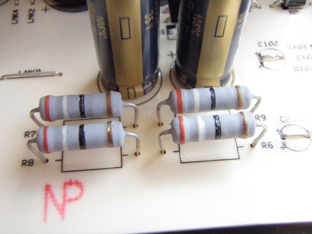 After, with Captain Caddock in place: 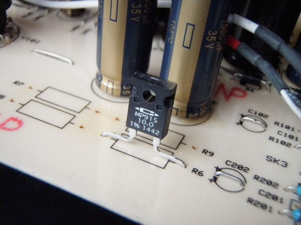 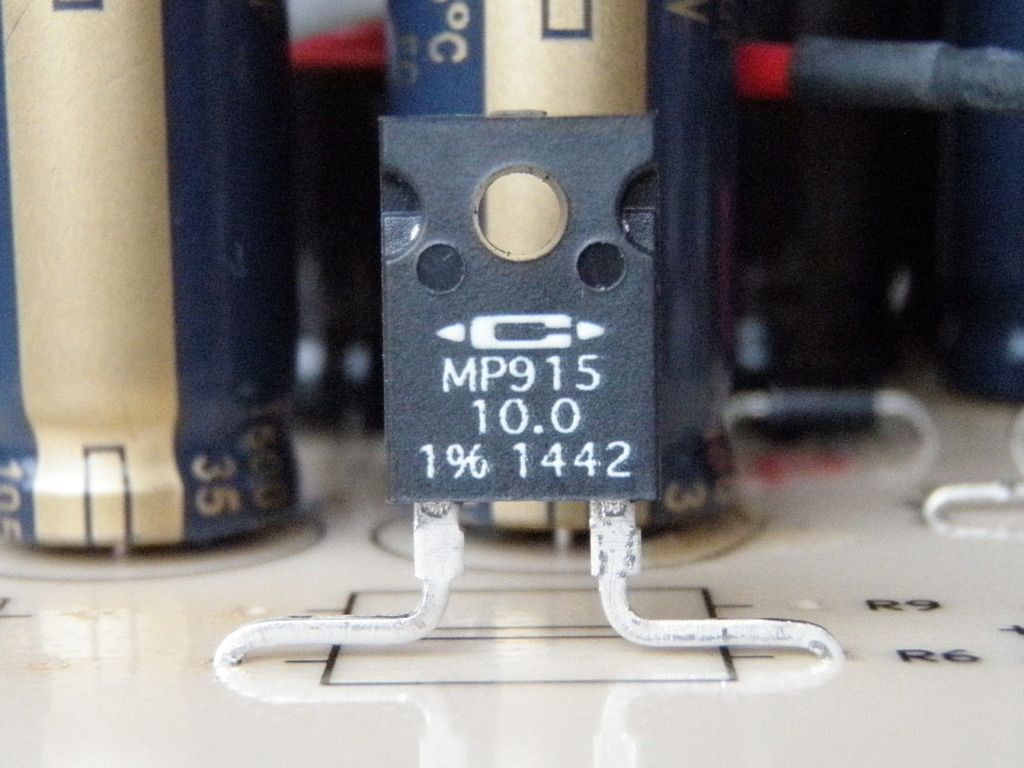 The output capacitors (green) are dangerously close to the volume control/headphone socket board. I put some electrical tape on the solder side for isolation: 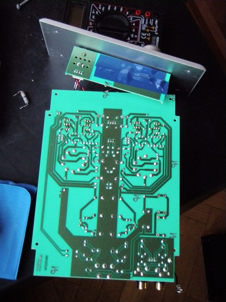 When putting the main board in the case, some leads actually touched the tubes which seemed not a good thing. Used some blue tape again to keep them together: 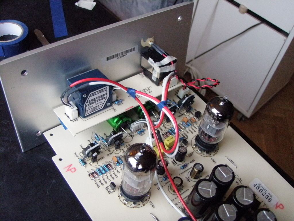 The amp is now playing with Mike's matched 6N23P tubes. Report will follow after some burn in. I would tend to NOT run the Captain Caddock "Naked" and would deffo shove a heatsink onto it matey  All the best, Mike. |
|
|
|
Post by PinkFloyd on May 31, 2015 20:54:37 GMT
Desolder the 1000uF coupling caps (green MUSE) and fit them thus: 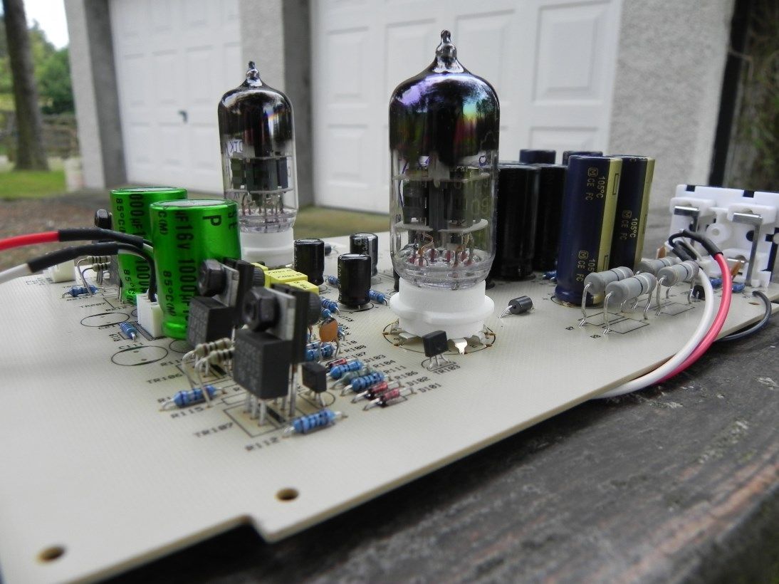 |
|
Deleted
Deleted Member
Posts: 0
|
Post by Deleted on May 31, 2015 21:17:36 GMT
I agree. It is too small too dissipate 10W on it's own, and has been designed to bolt to a suitably sized heatsink, just like a power transistor.
Alex
|
|
|
|
Post by PinkFloyd on May 31, 2015 21:24:37 GMT
Hey Peeps, from some discussion at headfi, I remembered the FULL Mod I did years ago. If you want to hear the FULL TRUE X-CAN potential than complete the Direct Wiring Mod: Get rid of those wired connectors and solder the wires directly to the printpads. There are few extra audio degrading cap/res/oxid. transitions with those wire-wraping pins/connectors. After direct soldering to pads/potmeter/cinchs, SQ IMPROVED MAX. the muffled layered veil and "slow capped" transients lifted. It sound Real Life-like now, you'll hear immediately.  Frankensteined with 2x12V/2A=48W toroid.  Add some rubber feets to reduce microphonics.  Input wires soldered directly to cinchs and to the input resistors, bypassed the input-elco caps that goes into the volume potmeter. After the potmeter comes an input-mkt cap anyway! I redirect/solder the amp output before the hp resistors to the (bypass) output-cinchs (left-side) to use as Pre-Amp Output now.  Those tube rubber damping rings are essential, if you want get rid of microphonics/ringing from tube vibration/temp. fluctation etc. Now tapping on the case, I can't hear microphonics anymore.  Inputs and Outputs Close-up.  Close-up wires from the potmeter, hp output and "pre-amp" output to the back. I keeped the original 2x 220uF and added 1x 680uF and 1uF MKP VISATON's: Superb lows and SUB(woofer) bass plenty now. Although I have 4PCS Nichicon ES 470uF 16V MUSE BP Audio and 2pcs MUNDORF MCAP 10 µf 400V for replacement, I'm already satified with the SQ now, lazy to change atm.  Close-up the (left-side) potmeter/hp output print.  I use 6x 4700uF/35V unknown? cheap (J.d) caps and re-used those original 4x 2200uF in the (lower uF) sides.  --- Overall I can't hear anything that need improvement now, as I'm hearing the life-like SQ as "Alive" there already done. That is "wrong" in so many ways but I love it! It looks more like a BDSM machine than a headphone amp with those cock rings on the valves and those totally "lead inductance" rich red mama honkers.... that thing is RFI city man! Been there and done it many years ago and I am sorry to tell you that the sound you are enjoying is laced with distortion, radio frequency interference and lead inductance. It's a GOOD sound, I'm not knocking it, but you have totally / unnecessarily over egged the pudding there mate. Your valves don't need cock rings.... if they are microphonic then replace them with new ones..... no valve / tube needs a cock ring to perform at its best. Mike. |
|
|
|
Post by cdsa35000 on May 31, 2015 22:01:36 GMT
|
|
|
|
Post by PinkFloyd on Jun 1, 2015 20:08:52 GMT
Years ago I used to attach a couple of suitably sized O rings to the valves (http://www.ebay.co.uk/sch/i.html?_from=R40&_trksid=p2050601.m570.l1313.TR0.TRC0.H0.Xo+ring.TRS0&_nkw=o+ring&_sacat=0) if they were microphonic but these days I throw microphonic valves straight into the bin..... Herbies dampers are just rubber o rings but orange instead of black. I can see the point of using dampers in a power amp with loudspeakers where the amp may be subject to in room vibrations from the sheer air flow from the speakers but in a headphone amp they don't do anything apart from making the o ring suppliers a few pennies richer  These things cost me about 5 PENCE each back in 2007:  Herbies rings are an absolute JOKE of a price but you've got to admire his cheek selling an "orange", penny a pop, o ring for megabucks. I think people got wise to them, and realised they were simple o-rings, so "Herbie" had to get a bit more inventive and now sells his "ultrasonic" rings........ herbiesaudiolab.net/tube.htm A total waste of money but the placebo effect may please some. I was serious when I was referring to "cock rings".... why pay more? www.ebay.co.uk/itm/Black-Beaded-Penis-Rings-Stop-Premature-Ejaculation-Erection-Impotence-Delay-Aid-/181712082349?pt=LH_DefaultDomain_3&hash=item2a4ee255adwww.ebay.co.uk/itm/BIG-O-PENIS-Ring-STOP-Premature-Ejaculation-Erectile-Disfunction-erection-aid-/381253932644?pt=LH_DefaultDomain_3&hash=item58c4815664I have bypassed the tracks and wired "direct" on more than one occasion over the years and can categorically state that the "improvement" (if any) is nowhere near as noticeable as a cap / valve / PSU upgrade..... I have used silver cable, 99.999% OFC copper cable, all sorts of cable and it all sounds the same to me....... I have ONLY used it on amps that were "fried" and have never gone full out with a "total" cable job....... I've got 12 virgin X-CAN V2 amps in stock so will experiment on one of them at the weekend. I like the way that you soldered the input wire "direct" to the quad phono socket but if you want to do it properly then you have to remove the phono socket on your source and amp and solder the out / in connecting cable directly to the amps input..... been there, done that and the end result?................ erm..... Two inseperable pieces of equipment that are "perma bonded" together by a piece of cable......... did it sound better? No, not really  Mike. |
|
|
|
Post by cdsa35000 on Jun 1, 2015 23:09:53 GMT
Yes, I know what you mean, I'm sure if you hardwired the toroid psu directly to the board too, SQ will improve too.
Surely hardwiring, shortening the interlinks/cables and stripping the cases, put the boards/prints into one (PC) big tower case will be the max. SQ improving mod.
But to me there no point to do it, because Im now totally satified with SQ now.
Before that "free" direct-wiring after the caps/psu mod, I still wasn't satified with the SQ improvement as I still hear some "sound compression" caused by extra material junctions and start searching the cause.
So after reaching the SQ satifaction level, there's no need to further improve, just enjoy now is enough and forget the work.
|
|
Deleted
Deleted Member
Posts: 0
|
Post by Deleted on Jun 4, 2015 22:14:12 GMT
Edit.
|
|
Deleted
Deleted Member
Posts: 0
|
Post by Deleted on Jun 4, 2015 23:12:04 GMT
Hi Navermyr
Although better than no heatsink, a heatsink that size is likely to have a thermal dissipation of only around 12 degrees C/W.
It will make very little difference to the internal temperature of a resistor dissipating anywhere near 10W.
You may even see the heatsink change colour over a period of time due to how hot it gets if the resistor is actually dissipating anywhere near it's rated power.
Regards
Alex
|
|
Deleted
Deleted Member
Posts: 0
|
Post by Deleted on Jun 7, 2015 18:06:18 GMT
Edit.
|
|
Deleted
Deleted Member
Posts: 0
|
Post by Deleted on Jun 7, 2015 22:02:50 GMT
I wouldn't want any heat source next to any electrolytic capacitors if you want them to have a long service life.
Panasonic FC , for example are rated at "Endurance : 105°C 1000 h to 5000."
Those hours quickly increment when you leave the amplifier on for many hours at a time, or continuously as many valve amplifier owners often do. At least the original resistors were well spaced with air flow around them and not as close to the electros.
Keep the temperature of the electros way below their temperature ratings and they may even last 30 years with regular use.
Alex |
|
Deleted
Deleted Member
Posts: 0
|
Post by Deleted on Aug 18, 2015 18:49:27 GMT
Edit.
|
|