|
|
Post by PinkFloyd on Apr 14, 2012 21:04:59 GMT
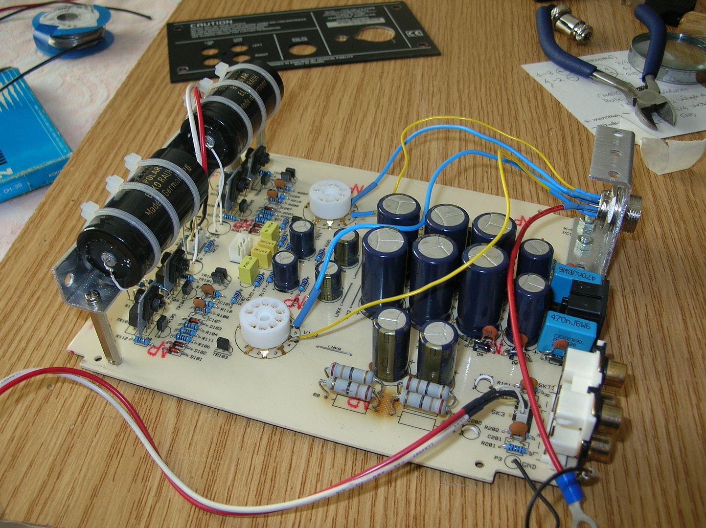
I got an e-mail from Maximiliano López López in Madrid and, with his permission, am publishing it here.... Feel free to discuss and, Maximiliano... please do join the forum, your English is superb and a LOT better than any attempt I may make at speaking Spanish  Here is what Max has done to his V3: "Hello, Mike, the reason to send this message to you is to suggest a modification I’ve made in my MF v3 headphone amplifier with so good results that I think it worth the effort. I have not write in the forum because my limited English and because is PSU related so, if you consider it of interest, please use it at your convenience.
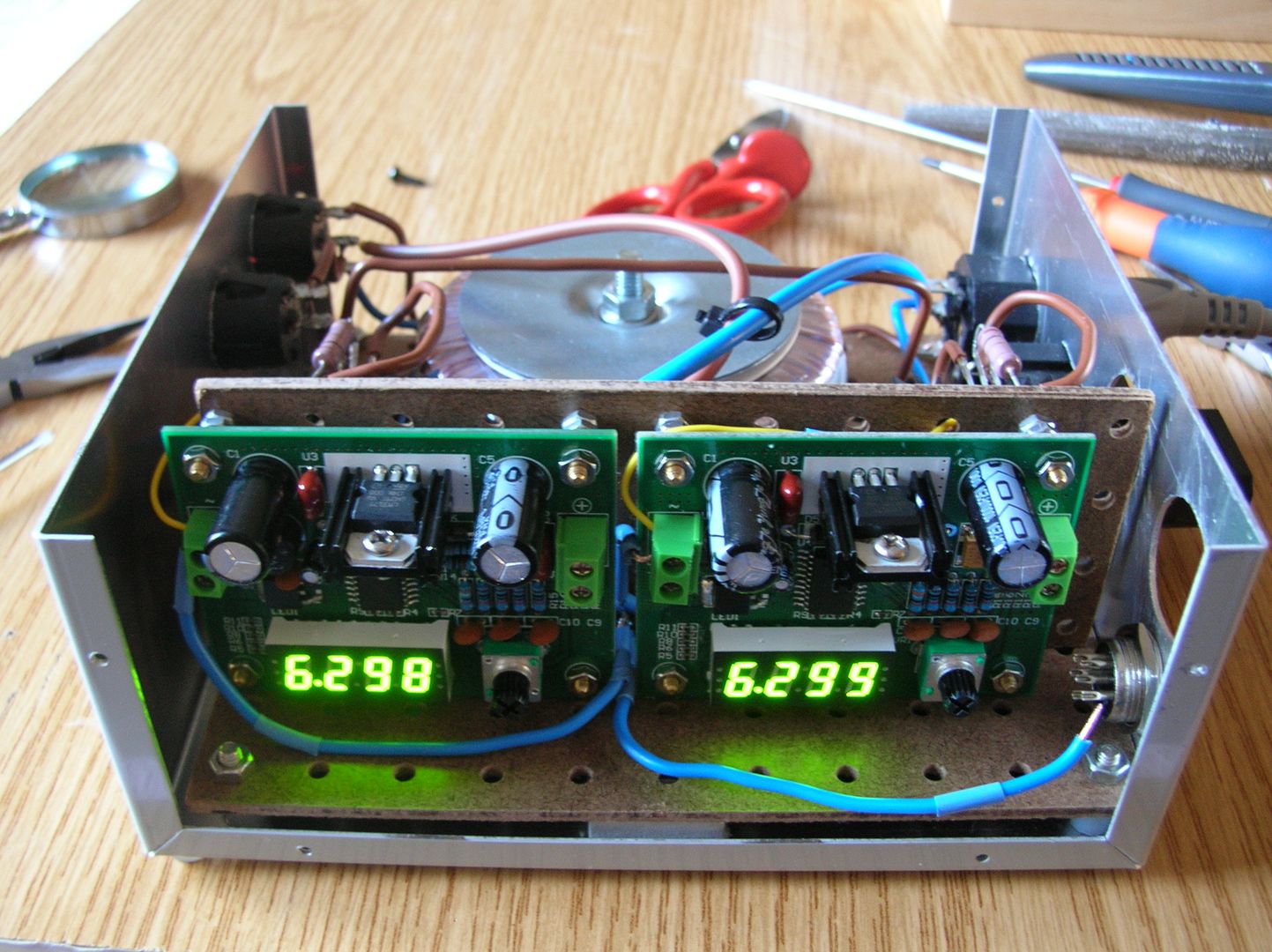
As many other amps, the MF has the heaters connected in series but I´ve found that the sound quality improves significantly with the heaters in parallel and are regulated in voltage.( a further improvement is regulate them in current as well).In my case I've used a second transformer with two 12V secondaries in a separate enclosure due to the need of heat dissipation.
My tubes are Russian 6N6P and they are a current hungry beasts so the regulators runs very hot. With other tubes this cannot be a problem. For voltage regulation I use two LM317T based modules.The sound is awesome with better dynamics and very transparent with more subtle details and finesse.
At first, due to a bad manipulation for sure, one channel blew out. The left one from the front ( the same as others in the forum ¿¡?!). I had to change two resistors and the darlingtons. I discovered your web page when I was in disposition to sell my MF because I´ve recently purchased an EarMax Pro. But, with the mods you suggested the improvement levelled the two amplifiers.
With the heaters in series, the MF wins with no doubt. So I am very grateful to you for a very informative page with a lots of good quality pictures and very useful information.
Best regards Maximiliano López López.
Madrid, ESPAÑA"     |
|
Deleted
Deleted Member
Posts: 0
|
Post by Deleted on Apr 14, 2012 23:45:21 GMT
That's some very interesting work there  I'm particularly interested in more details on the power supply and those boards. ( hoping that it did not blow up 6.3 seconds after the photowas taken  ) Thanks for sharing. |
|
|
|
Post by szoze on Apr 15, 2012 5:43:08 GMT
Very impressive.
|
|
|
|
Post by phantomax on Apr 15, 2012 7:37:48 GMT
"I'm particularly interested in more details on the power supply and those boards.
( hoping that it did not blow up 6.3 seconds after the photowas taken )"
Hello! It has been working for one week flawlessly. The only drawback for now is that I can't close the enclosure because is a little bit tigh for enough heat dissipation and the voltage fall down after a while.
I think 12 V secondaries are too much to regualte at 6,3 V. Probably secondaries of 9 V are better option for this modules.
I had made the same mod with a Copland pre and my DIY DAC without this issue but I fitted different modules although based always in LM317T. All of them get very hot but they remains stable.
Maxi
|
|
|
|
Post by PinkFloyd on Apr 15, 2012 9:37:52 GMT
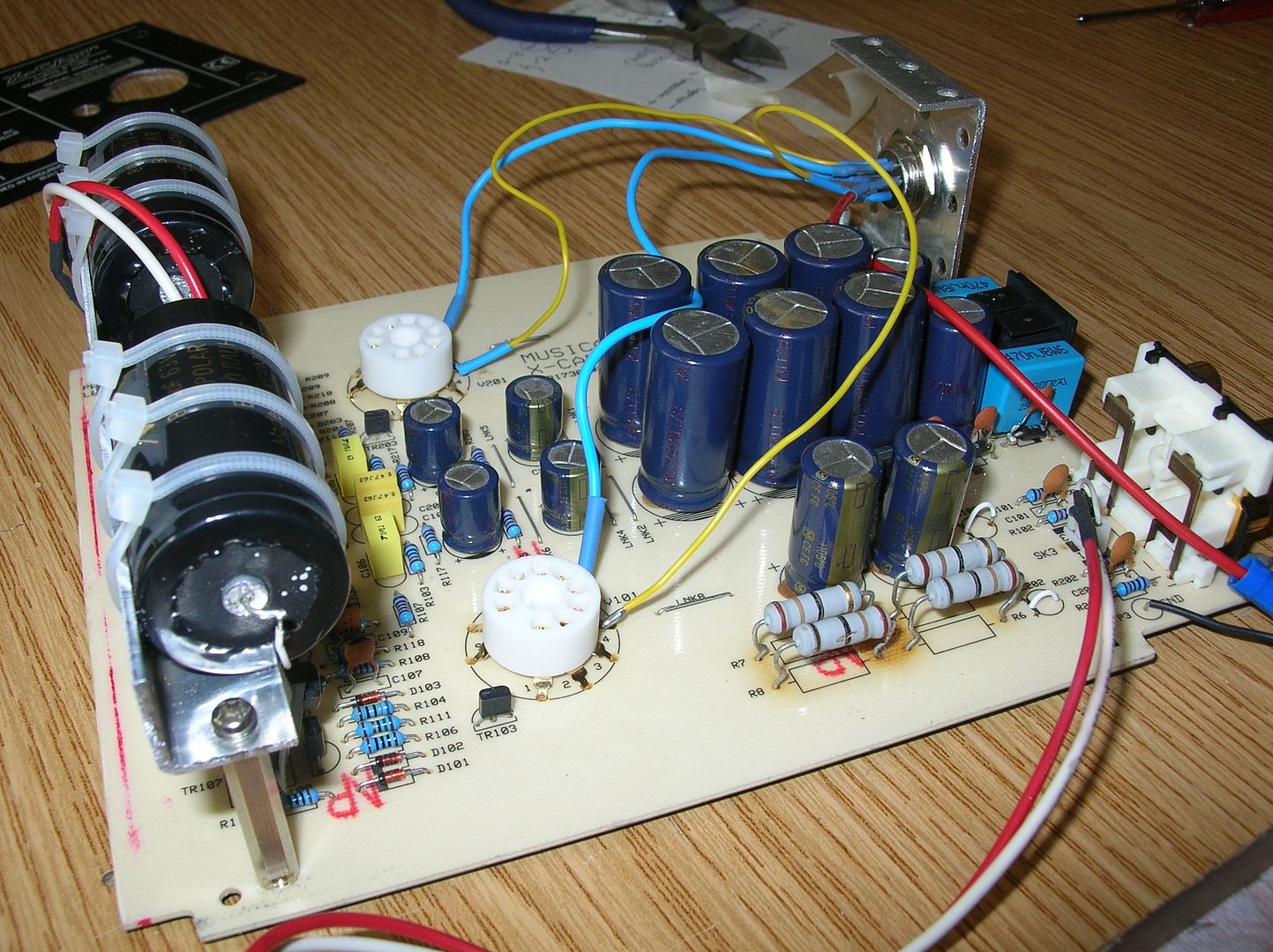
Maxi, As nice as those huge non polar caps look you've got a fair bit of lead inductance there.... ideally the caps should be as tight to the board as possible. It will probably sound great but a technician / professor (such as Frans) would probably be able to measure that inductance  Nice work, always good to see fresh ideas. Mike. |
|
Deleted
Deleted Member
Posts: 0
|
Post by Deleted on Apr 15, 2012 11:01:47 GMT
It has been working for one week flawlessly. Maxi Hi Maxi, Sorry, I did not mean it looked wrong, just that it reminded me of a bomb from a Hollywood film, with only 6.3 seconds remaining on the counter to cut the ? wire!  |
|
|
|
Post by szoze on Apr 15, 2012 13:43:13 GMT
Maxi, As nice as those huge non polar caps look you've got a fair bit of lead inductance there.... ideally the caps should be as tight to the board as possible. It will probably sound great but a technician / professor (such as Frans) would probably be able to measure that inductance  I replaced those 10uF polar electrolytics in the signal path of my x-can v3 with a couple large 10uF polyprolylene capacitors. The capacitors are axial and huge so the leads down to the circuit board are pretty long. I never thought about the lead inductance. In which way can that extra inductance affect the sound? I guess it forms some kind of filter (reconance circuit?) together with the capacitor. |
|
Deleted
Deleted Member
Posts: 0
|
Post by Deleted on Apr 15, 2012 15:42:56 GMT
a technical answer that omits the SQ..
inductance of a length of thin wire is around 1uH/meter.
so 10 cm of wire = 100nH. Add that to the length of PCB wiring that is also there, the series resistances in circuit, the length of the headphone cable and the (factor thousands) higher inductance of the driver inductance (as all inductances in series can be added like resistors) and you can get the idea.
On the input the same rules apply but impedances differ.
For decoupling caps that need to be very close to what needs to be decoupled and if relly high freq. are present that need decoupling (talking about MHz to GHz range) the lead inductance of caps may throw dirt...
resonances of a cap with 10cm long wires are in the 100MHz to GHz range.
|
|
|
|
Post by szoze on Apr 15, 2012 15:58:51 GMT
a technical answer that omits the SQ.. inductance of a length of thin wire is around 1uH/meter. so 10 cm of wire = 100nH. Add that to the length of PCB wiring that is also there, the series resistances in circuit, the length of the headphone cable and the (factor thousands) higher inductance of the driver inductance (as all inductances in series can be added like resistors) and you can get the idea. On the input the same rules apply but impedances differ. For decoupling caps that need to be very close to what needs to be decoupled and if relly high freq. are present that need decoupling (talking about MHz to GHz range) the lead inductance of caps may throw dirt... resonances of a cap with 10cm long wires are in the 100MHz to GHz range. Thank you Frans. A great answer as always. I beleive I will let those big film caps be  I am also curious about the output resistance of the x-can v3. I will keep a pair of AKG k701 and would like to change the output resistance of the amp to be 120 Ohm. I don't have the schematics and don't know which resistors I should modify. |
|
Deleted
Deleted Member
Posts: 0
|
Post by Deleted on Apr 15, 2012 18:08:24 GMT
R114 and R214
the 33 Ohm between the 2 resistors that are located between the output devices.
If you don't like it you can always change it back.
|
|
|
|
Post by szoze on Apr 15, 2012 19:22:35 GMT
If you don't like it you can always change it back. Of course.  Thanks once again. |
|
|
|
Post by PinkFloyd on Apr 15, 2012 21:29:50 GMT
SZOZE....... If you don't like it you can always change it back. Of course.  Thanks once again. I'll give you another one which is worth an even BIGGER thank you (when you hear the improvement)  REMOVE those 10uF input coupling caps (throw them in the bin) and jumper over the pads with a wire link:  They are totally unnecessary unless there is "excessive" DC on your source output..... www.rock-grotto.co.uk/dcoffset.htm"NO" cap is better than a cap in the signal and a non polar behemoth "boutique" cap with lead inductance is far worse than a shitty general purpose electrolytic.... We are talking belt and braces here.... the input coupling cap is there to prevent "excessive" DC entering the amp and the output coupling caps are there to ensure that no "excessive" DC destroys your headphones. If your source is pretty "modern" it will have either a DC servo or output coupling caps so the DC entering your amp should be pretty much ZERO..... I ALWAYS dispense with the input caps on a V2 / V3 but ALWAYS keep the output coupling caps.... the input coupling caps are there because there will always be ONE person out there who has a source that is outputting 1000 volts DC and because of that possible "eventuality" they have to make sure the amp is monkey proof. Remove those 10uF caps, jumper over the pads and then give me a thank you in "bold" letters please  When I say "zero ohm link" I am basically saying either a piece of wire or an offcut from a capacitor leg.... you can buy zero ohm resistors but a piece of wire is your best bet. You can also jumper over with an axial ferrite if you live in an area with high RFI..... This is one situation where LESS is more  |
|
XTRProf
Fully Modded
Pssst ! Got any spare capacitors ?
Posts: 5,689
|
Post by XTRProf on Apr 16, 2012 5:15:52 GMT
Use boutique OCC Copper or Silver will be best!
|
|
|
|
Post by szoze on Apr 16, 2012 5:18:48 GMT
SZOZE....... I'll give you another one which is worth an even BIGGER thank you (when you hear the improvement)  REMOVE those 10uF input coupling caps (throw them in the bin) and jumper over the pads with a wire link: That sounds great. I was actually thinking of this after seeing it on your homepage. I am not sure about my cd-player and dc out. I will have to check it with HArman and try this mod. Then I will thank you  |
|
Deleted
Deleted Member
Posts: 0
|
Post by Deleted on Apr 16, 2012 6:08:11 GMT
SZOZE....... I'll give you another one which is worth an even BIGGER thank you (when you hear the improvement)  REMOVE those 10uF input coupling caps (throw them in the bin) and jumper over the pads with a wire link: That sounds great. I was actually thinking of this after seeing it on your homepage. I am not sure about my cd-player and dc out. I will have to check it with HArman and try this mod. Then I will thank you  Anybody doing any kind of modifications to any electronics gear, should have at the very least, a cheap Digital Multi Meter. They can be obtained for as little as $20 these days. This could save you from destroying more expensive equipment, or perhaps even save your life in the case of mains powered gear. Alex |
|
|
|
Post by szoze on Apr 16, 2012 6:40:32 GMT
Anybody doing any kind of modifications to any electronics gear, should have at the very least, a cheap Digital Multi Meter. They can be obtained for as little as $20 these days. This could save you from destroying more expensive equipment, or perhaps even save your life in the case of mains powered gear. Alex Of course  I have had my Fluke multimeter for many years now and I intended to use it. Anyway I will call Harman to be on the safe side.  |
|
|
|
Post by PinkFloyd on Apr 16, 2012 8:17:43 GMT
Harman will tell you everything is perfect.... always check it yourself  Same goes with gear, don't ask someone what it sounds like.... use your own ears because, at the end of the day, it's you who will be listening to the gear. |
|
|
|
Post by szoze on Apr 16, 2012 8:44:39 GMT
Harman will tell you everything is perfect.... always check it yourself  When I check the source for the DC, how shall I do it? I mean shall I check the voltage out of the source under certain conditions (on, off, during music playing) Maybe I should use an oscilloscope? |
|
Deleted
Deleted Member
Posts: 0
|
Post by Deleted on Apr 16, 2012 10:05:32 GMT
Harman will tell you everything is perfect.... always check it yourself  When I check the source for the DC, how shall I do it? I mean shall I check the voltage out of the source under certain conditions (on, off, during music playing) Maybe I should use an oscilloscope? szoze The easy way is to plug your RCA leads into the source and check for DC at the other ends of the RCA cable. You are unlikely to see more than a couple of millivolts, or none at all if the source has output capacitors. If the source uses a switch mode PSU you may feel a little tingle from the earth side of the RCA plugs when you plug the leads in.This is normal with SMPS sources, especially if the amplifier uses a 3 pin mains plug. Alex |
|
|
|
Post by szoze on Apr 16, 2012 10:13:20 GMT
Thanks Alex. I measured on the RCA plug and the DC voltage there is -4,8 mV. Yes, the source uses switched mode psu.
|
|
|
|
Post by phantomax on Apr 20, 2012 10:45:17 GMT
Hi,all of you! The PSU heaters is finished (almost)  . I am no very proud about its appearance. Aesthetically is not very stylish, but the need to place the heatsinks outside was a real nightmare so I am going to let it be for now. I've said almost because there is a very low level hum in one channel. It is not annoying but I wish to identify where is the origin. Probably the umbilical cable is picking it somewhere because in the same mods of the DAC and the Copland Pre the PSU were inside the original enclosure and I haven't this problem. To CJ : Ha, ha! I am laughing now but I was not so confident the first session sniffing for scorching and looking at those green numbers to get almost auto-hipnotised with the threat of an explosion.  About the inductance, thank you Mike and others for your advice. For sure you are right but I had to adopt a compromise solution. The question is if it compensates to place a better ( in theory) capacitor. About the SQ my initial thoughts remain the same. More powerful and detailed than ever. Maxi |
|
elysion
Been here a while!  Team Anti M$ AND Facebook.
contra torrentem
Posts: 2,375
|
Post by elysion on Apr 20, 2012 18:27:15 GMT
Great work, Maximiliano!  Welcome on the forum.  |
|
|
|
Post by phantomax on Apr 23, 2012 10:06:46 GMT
Hum noise fixed! I made a silly mistake connecting the grounds to the upper left corner instead to the lower one, where the paint is removed to ensure a better contact.  Thanks elyson for your words! |
|


 )
)

 Thanks once again.


