Deleted
Deleted Member
Posts: 0
|
Post by Deleted on Dec 18, 2012 14:54:21 GMT
Hi Syd, if you do go for the Airlink transformers this may help  |
|
Deleted
Deleted Member
Posts: 0
|
Post by Deleted on Dec 18, 2012 17:12:35 GMT
Hi Alex yes i still have your amp running at 15W 1A and found no need for trying to squeeze more out. I would say that I've been surprised how far 15W can go but I've had 1.5W tube amps so no big surprise. just super SQ  Hi Syd here is my PSU unit the upside down Monkey ;D ;D not the only way of doing things but gives you some idea of the transformer size.  BTW i had great service from Airlink and nice transformers which arrived a few days after ordering. pretty impressive any questions just ask away  take care Hi Shaun Makes the original SC PSU look a little puny ! Don't forget that their PSU may have dissipated a tiny bit more heat than yours due to 21-0-21V toroidal. That means your PSU has quite a bit more heatsinking than necessary. Perhaps you did intend upping the power ? ;D Kind regards Alex Hi Alex yes big heat sinking.  but it was the smallest case i could find that matched My class A case.  overkill as usual. ;D ;D nope never really felt the need for more power. it's great as is and I've heard many a great sound spoiled by the greed of a few more watts.  take care |
|
Deleted
Deleted Member
Posts: 0
|
Post by Deleted on Dec 18, 2012 20:59:31 GMT
Hi Shaun
You do of course realise that I was in a round about way suggesting to people like Syd that they didn't need to spend up big on the case for the PSU unless they are trying to match the looks of both parts.
A minor problem is that as we are using 2 large toroidals (at least) that we can't use a large plastic case, and it is rather fiddly fitting a rear mounted heatsink on a normal 2U rack case.We can of course smear the whole area of a reasonable sized heatsink with heatsink compound from a tube before bolting it all together with a couple of additional screws in the centre between the PSU PCBs for extra rigidity.
I used the same heatsink as the amplifier because it was a good physical fit on the rear panel, although perhaps a heatsink of the same height, but not quite as long would have been better, as it would then leave more room for connectors and the IEC mains socket. Yes, mine is still overkill too.
Kind Regards
Alex
|
|
Deleted
Deleted Member
Posts: 0
|
Post by Deleted on Dec 18, 2012 21:49:34 GMT
Holy windings batman! I'm getting lost already. So is it 18-0-18, 20-0-20, 21-0-21, 22-0-22  Basically, to make the amp at 15w 1A but have the option to tune up to a tad more if required (play moozac in the mountains and hear it on the coast), which one is the actual doughnut of choice? Ta ps I don't need icing sugar or sprinklings, just straight forward or maybe jam filled..... |
|
Deleted
Deleted Member
Posts: 0
|
Post by Deleted on Dec 18, 2012 22:04:51 GMT
Holy windings batman! I'm getting lost already. So is it 18-0-18, 20-0-20, 21-0-21, 22-0-22 Basically, to make the amp at 15w 1A but have the option to tune up to a tad more if required (play moozac in the mountains and hear it on the coast), which one is the actual doughnut of choice? Ta ps I don't need icing sugar or sprinklings, just straight forward or maybe jam filled..... Hi Chris My recommendation,because many of you guys seem to have access to some toroidals in different values to generally available Downunder, is to do what Shaun has done using the 160VA 20-0-20 toroidals instead of the 80VA if you have enough room. Using 21-0-21 will allow you to up the voltage supply a few more volts and obtain several more watts.However you are unlikely to notice any difference. I can't use 2 x 160VA in my rack case as I already have 2 x 18-0-18 30VA toroidals for the preamp inside the case, so I will stick with my 21-0-21 Harbuch transformer with separate windings. Kind Regards Alex |
|
Deleted
Deleted Member
Posts: 0
|
Post by Deleted on Dec 18, 2012 22:26:43 GMT
Right you are, cheers Alex.
|
|
Deleted
Deleted Member
Posts: 0
|
Post by Deleted on Dec 18, 2012 22:45:16 GMT
Hi Alex ''from a tube'' i thought you'd gone off tubes ;D ;D you are right on the heat sinking which is why i took the easy option and went Hifi 2000. nothing toooo wrong with keeping those regs running cool though. and nothing wrong with over kill. manufacturers are always looking for ways to cut costs and usually heat sinking is one of the first casualties. so the commercial Class A that i had (MF A1 original hurump 20 ish Watts) had the nick name the toaster and did run that hot. for the main amp though i do think that it's important not to under spec the heat sinking. i have a U4 case and she still runs warm but not hot. again overkill but i had such a case to hand. but i would not want to go much under the U3. the heat sinking that you have used is a little better spec-ed for the size than the equivalent U2 Hifi 2000 so I'd not want to use that case for the sake of longevity. Alex that transformer you have is a good one and going down the two transformer route is our only chance of getting anything like the same performance that you get from separate windings. Hi Chris the 20V 160VA transformers that i have go back to a discussion (first few pages of this thread) i just went for the ones that came closest to Alex's super nice 21V (individual secondaries) transformer. then i just upped the VA a little because I'm a little like that about such things. i put a mention in for Airlink because i know that they work well and they are a great company to buy from. if you have room do go dual mono (2 transformers) but after that as Alex has mentioned 80VA will be enough but the cost difference is pretty small to have the 160VA big boys. i agree with Alex that you are unlikely to notice a few more Watts or even 10 more for that matter. one thing for sure this is a great amp  take care |
|
Deleted
Deleted Member
Posts: 0
|
Post by Deleted on Dec 19, 2012 11:34:27 GMT
Which case did you get Shaun?
I don't remember you posting a pic?
Syd
|
|
Deleted
Deleted Member
Posts: 0
|
Post by Deleted on Dec 19, 2012 11:36:40 GMT
Thanks Alan, it will! You know I need all the help I can get, fortunately never a problem getting it here!
Syd
|
|
Deleted
Deleted Member
Posts: 0
|
Post by Deleted on Dec 19, 2012 11:56:58 GMT
hi all Here are some pictures of my Alex Lite SC Class A build. Frogs in a box time again ;D The PSU Hifi2000 U2 dissipante steel case 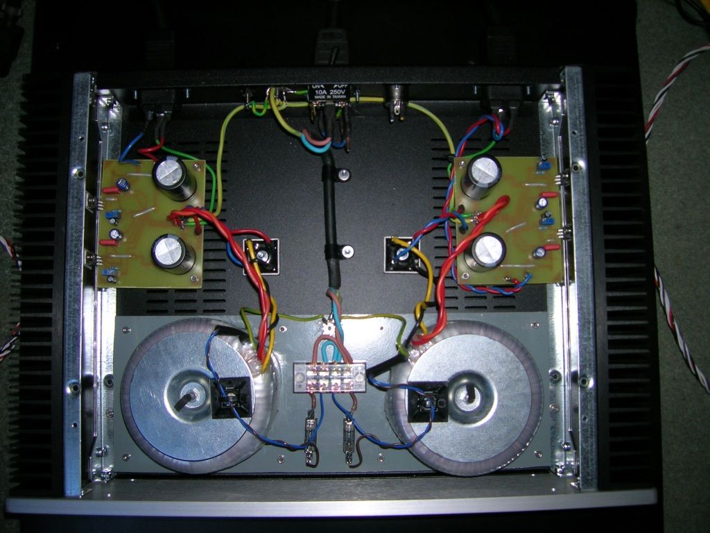 The transformers are mounted on 3mm Aluminum sheet isolated from the chassis and separately earthed back to the IEC input. Power output sockets are IEC Female to avoid any exposed voltages should the plug become disconnected. The reg boards are my etched versions so may be a little larger than the ones Will has in mind. I have 20.2V + & – on both reg Ops Power chords are silicone rubber 16A mains cable (it’s sooo much less stiff than the regular stuff) The Amp HIFI2000 U4 dissipante Ali case Uses 10A power cables to hook up the OP devices and 6A for the JLH’s except for the long runs from the JLH which i used screened IC cable for as per Alex's build. The amp boards and DC offset boards are taken from Will’s designs posted on the HA/PRE thread (thanks Will). 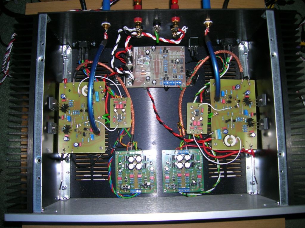 Of all of my etches, I’m most pleased with the DC offset correctors as they are pretty fine tracks which I doubted the press and peel would cope with. It did a really good job on those boards. The etching process was fun and I was amazed to end up with working boards at the end of it. by the way i used TL071 in the corrector which gave 26mV and 27mV which is pretty respectable. i had 10 to choose from and while some where lower i just went for the best match. Internal signal IC are Shark wire OFC copper in a pseudo balanced configuration. It’s double screened (foil and braid) as I wanted to make sure that noise was kept to a minimum (and in keeping with the amp ‘’it’s Australian’’). I may experiment a little with that later. I have fitted the speaker protection board which gives around 5 seconds delay on start-up and switches off pretty quickly avoiding start up and shut down thumps and bumps. Initially I was going to run the AC for it from the PSU (note UN needed XLR socket) but in reality I just soldered a link from the positive DC input to one of the AC inputs as per the testing procedure outlined in the build guide. I also fitted a quick switch off on the thermal shut down connection as per Alex's build. Speaker OP cable is 2x 10A PTFE silver on copper stranded per run which I use for my LS cables. JLH boards are Greg’s fantastic work. Thanks Greg. The chassis is UN earthed but I have fitted a binding post to allow that option if needed. I found that it was not and it runs very quiet indeed. So as I say this amp is a real joint effort and all the better for it. It also happens to sound superb (well stunningly good actually) Take care Hi Syd this post must have passed you by ;D ;D also the one on the previus page i used Hifi 2000 for PSU and Amp boxs. take care |
|
Deleted
Deleted Member
Posts: 0
|
Post by Deleted on Dec 19, 2012 12:42:37 GMT
Hi Shaun
I assume that those figures were without something like a 1K resistor connected to each input, or perhaps a working Class A preamp plugged in ? I think that when the inputs are terminated, even with the TL071, you would have had something like a couple of mV, or if lucky, closer to 0mV.
Kind Regards
Alex
|
|
Deleted
Deleted Member
Posts: 0
|
Post by Deleted on Dec 19, 2012 13:32:33 GMT
Hi Shaun I've no idea how I didn't register this in my brain, I spent hours over the last few days re-reading this thread  Its a great job you've done anyway, I had been thinking of using a couple of the Chinese HA cases that I have spare, one channel to a case, until I realised the heatsinking that's necessary. Syd |
|
Deleted
Deleted Member
Posts: 0
|
Post by Deleted on Dec 19, 2012 14:51:36 GMT
Hi Shaun I assume that those figures were without something like a 1K resistor connected to each input, or perhaps a working Class A preamp plugged in ? I think that when the inputs are terminated, even with the TL071, you would have had something like a couple of mV, or if lucky, closer to 0mV. Kind Regards Alex Hi Alex yup that was before we spent hours wracking your brain to find out that i had reversed the MPSA18. but the up side was i learned plenty from our little adventure and that counts big time for me. now DC offset is way down close to zero. I've changed the front end to those Motorola units since and it plays all day without any issues. just sounds superb Syd my advice is don't skimp on the Heat sinks. i had a look at the specs from the original Altronics ones and even though they are compact but have superb specs. i already had the U4 case but did check anyway and found that the U3 Hifi 2000 heat sinks were closer to the ones that Alex is using spec wise. we need cool runnin' here. take care |
|
Deleted
Deleted Member
Posts: 0
|
Post by Deleted on Dec 19, 2012 23:20:58 GMT
Hi Shaun
I have a Sugden here, A21, and the sides get really hot so I'm forewarned, and will certainly be taking your advice. Hopefully get similar cases to yours after the post gets back to normal.
Syd
|
|
Deleted
Deleted Member
Posts: 0
|
Post by Deleted on Dec 19, 2012 23:34:27 GMT
I'm sorting out the bits for Will's PSU board now. The BOM for it gives a range of capacitors for various locations but I can't find any write up on which values to choose (no doubt Shaun will find it in minutes... ) Everything else I've used or am about to order is for a standard build, changed to the OPA 134 s is the only variation. www.editgrid.com/user/willwoo/HiCurrentPSUThanks Syd |
|
Deleted
Deleted Member
Posts: 0
|
Post by Deleted on Dec 20, 2012 0:14:50 GMT
I'm sorting out the bits for Will's PSU board now. The BOM for it gives a range of capacitors for various locations but I can't find any write up on which values to choose (no doubt Shaun will find it in minutes... ) Everything else I've used or am about to order is for a standard build, changed to the OPA 134 s is the only variation. www.editgrid.com/user/willwoo/HiCurrentPSUThanks Syd Hi Syd Don't forget the 2x 2n2 caps (normal film type) across the 1M resistors to go with the 2 x OPA134. C3 and C8 could be 10uF 25V or higher. C4 and C6 100uF 35V or even 50V. C10 and C11 100nF 50 V, 63V or 100V They are just normal film caps. C1 not essentiual, but can be experimented with starting at 330pF 100V, Ther big electros can be from 4,700uF to 10,000uF with a minimum voltage of 35V. I am using 6,800uF 50V 85C snap in types there.. Electros are best rated at 105C , but not essential, especially in your part of the world. Don't use low ESR electros. Kind Regards Alex |
|
Will
Been here a while!  Ribena abuser!
Member since 2008
Ribena abuser!
Member since 2008
Posts: 2,164
|
Post by Will on Dec 20, 2012 8:31:41 GMT
I'm sorting out the bits for Will's PSU board now. The BOM for it gives a range of capacitors for various locations but I can't find any write up on which values to choose (no doubt Shaun will find it in minutes... ) Everything else I've used or am about to order is for a standard build, changed to the OPA 134 s is the only variation. www.editgrid.com/user/willwoo/HiCurrentPSUThanks Syd Hi Syd, the values are shown in the second column, and when you click th e link, a selection of caps will appear. These caps are physically the correct size (diameter, lead pitch) and also are suitable for the PSU at a minimum, no matter which you select. Some do have a higher voltage rating, but that won't affect things to much, and will be useful if you want to use these pcb's at a higher voltage. I did it this way to allow people to choose what 'flavour' caps to use, and to avoid prescribing a particular type. The only part you need to think about is the terminals, and choose the one with the correct amount of connectors. Also, just for clarity, Alex's comment about the 2n2 caps, 1M resistor and opa134 relate to the amp pcb, not the psu, just in case you go looking for those parts! Got your rogue LS device, will get a proper one away to you today |
|
Deleted
Deleted Member
Posts: 0
|
Post by Deleted on Dec 20, 2012 10:09:33 GMT
Hi Will
I understand what you're saying OK, I'm well impressed with how useful and comprehensive your BOMs have been. The bit I was left a bit mystified about was eg C4 100-1000 seemed a huge range (to me) and I wondered if there were some mods being done 'off thread' that would indicate the need to use say 1000 instead of 100. I'm taking it now that its sound tuning that is the reason, that is any will do the job but will influence the sound?
Syd
|
|
Deleted
Deleted Member
Posts: 0
|
Post by Deleted on Dec 20, 2012 10:15:14 GMT
That's spot-on Alex can sort out my order now, much appreciated.
Syd
|
|
Deleted
Deleted Member
Posts: 0
|
Post by Deleted on Dec 20, 2012 10:58:57 GMT
Syd
A voltage regulator will most likely be a little faster with small corrections into the smaller values ? Most S.C. designs for audio appear to typically use 100uF at the output of the voltage regulators too.
This shouldn't matter that much though while we stay completely in Class A conditions with it's constant current draw.
Regards
Alex
|
|
Deleted
Deleted Member
Posts: 0
|
Post by Deleted on Dec 20, 2012 11:39:26 GMT
Hi Syd, here is a pic of Alex's 2n2 mod. The 2n2 lies flat on the board, cut the leads to size tin a little solder onto both 2n2 leads and just touch the iron to the joint no extra solder required. Regards, Alan  |
|
Deleted
Deleted Member
Posts: 0
|
Post by Deleted on Dec 20, 2012 14:50:25 GMT
Hi Syd, you could go down the road of putting the traffos in separate cases like I have done. Your local computer man/shop doing repairs is bound to have junk PSU modules which he will let you have. Alan    |
|
Deleted
Deleted Member
Posts: 0
|
Post by Deleted on Dec 20, 2012 23:00:47 GMT
Hi Alan
Thanks for the pic, job done! Is there any reason for the OPA pins being identified, or was that for something else?
Regards, Syd
|
|
Deleted
Deleted Member
Posts: 0
|
Post by Deleted on Dec 20, 2012 23:05:40 GMT
That's a sturdy looking setup Alan. I'll keep it in mind though I'm presently thinking that since I can't use my Chinese cases for the PCBs etc then they may do for the traffos! I hadn't thought of that until your post, much appreciated |
|
Deleted
Deleted Member
Posts: 0
|
Post by Deleted on Dec 20, 2012 23:50:08 GMT
Hi Syd, when I looked at the board to see where the 1M was placed then turned it over it was easier to take the trace from pins two and six back to the 1M to be sure I was at the right spot, since the 1M is actually across these pins. If you look closely at your board you can see the copper strips run to each end of the 1M. Here is Alex's latest offset circuit. Alan  |
|


