Deleted
Deleted Member
Posts: 0
|
Post by Deleted on Oct 19, 2010 21:37:36 GMT
Mick, It is a vigortronix toroidal..... connect it exactly as shown in my picture. Mike. Ok, thanks Mike and frans, will have a go tomorrow had enough for today.  One last question, when adjusting the DC offset voltage, does this have to be done AFTER OR BEFORE, the headphone socket resistors are fitted. |
|
|
|
Post by PinkFloyd on Oct 19, 2010 21:54:34 GMT
Mick, It is a vigortronix toroidal..... connect it exactly as shown in my picture. Mike. Ok, thanks Mike and frans, will have a go tomorrow had enough for today. One last question, when adjusting the DC offset voltage, does this have to be done AFTER OR BEFORE, the headphone socket resistors are fitted. Adjust the DC offset to below 10mV before connecting the inputs / outputs to the board just so you know it's well down. Connect the entire shebang together (output resistors etc) and then measure again at the headphone socket.... let the amp run for about 30 minutes so it can warm up before doing the final settings..... It's simple Mick, you won't blow anything up... don't worry  Mike. |
|
|
|
Post by PinkFloyd on Oct 19, 2010 21:57:27 GMT
Its not obvious from the label what the make is Mike,, its an encapsulated one from Rapid 80va 18-18. Is it right to say that terminal 1 yellow on your photo is 18v and terminal 3 red in your photo is 18v, the other two being 0v connections. Mick. There are FOUR pads. The two OUTER pads are 18V the two CENTRE pads are 0V..... |
|
|
|
Post by PinkFloyd on Oct 19, 2010 22:13:29 GMT
I finished putting the board together last night but it was getting late and I was getting tired so I left wiring the mains to the toroidal till today after I got in from work. After checking everything one last time I fired her up and went about checking the voltages as in the instructions they were both just over 1.2v so were adjusted to 1.2v easily enough then the dc offset set to zero. I have spent the last 2 1/2 hours listening to different albums via my Sqeezebox and have to say that Mike is absolutely spot on this thing is fantastic, very musical and vocals just seem to flow crisp and clear. Can't wait till its had a few more hours on it to see how it improves and I've built it stock with no upgrades not even the filter caps on the mains input. Listening to Van Morrison Astral weeks, best its ever sounded for me yet and thats from a valve addict  Nice one Bizzie  As with all amps, things will improve over the next couple of hundred hours of use.... you may experience a couple of troughs but it will peak to it's full potential within the next few weeks of normal listening. Any pics? I love seeing under the bonnet snaps Enjoy the music! Mike. |
|
|
|
Post by PinkFloyd on Oct 19, 2010 22:20:52 GMT
Ian, I have PM'ed you.... I can "easily" tweak the settings so the Panda will get your K-701 rattling on their end stops at 12 o' clock on the volume if you like? A few simple adjustments |
|
Deleted
Deleted Member
Posts: 0
|
Post by Deleted on Oct 20, 2010 0:03:22 GMT
So that means i have to swap the red and the black wire over then, because as is now, i have:
yellow.... pad 1 18v lead
orange.... pad 2 0v lead
red.......... pad 3 18v lead
black........pad 4 0v lead.
I don`t think mine is a victronic, no markings on the box say it is, or on the toroid itself.
Mick.
|
|
Deleted
Deleted Member
Posts: 0
|
Post by Deleted on Oct 20, 2010 8:51:22 GMT
Twist or solder the orange and red lead together (do not connect any wires to the board yet)
Take your meter and set it on AC voltage (200V AC setting or something)
Now power the transformer
Measure AC voltage between yellow and orange/red.
Should be around 20V AC (+/- 2V)
Then measure between orange/red and black
Should read the same voltage 20V AC. (+/- 2V)
Then measure between yellow and black.
Should read double the voltage so about 40V AC. (+/-4V)
If this is correct then power of the transformer
connect TX YELLOW lead to Mike's black connection point (corner connector)
connect TX ORANGE next to it (Mike's red connection)
connect TX RED to the other centre contact (Mikes orange wire)
connect TX BLACK to the other corner connector (Mikes yellow wire)
This should do it.
If these voltages check out it should work.
IF you measure the 20V AC but no voltage instead of the expected 40V AC (be sure your meter makes proper contact) then swap the red and black lead in the connections above.
Hope this makes sense
|
|
Deleted
Deleted Member
Posts: 0
|
Post by Deleted on Oct 20, 2010 9:33:44 GMT
Twist or solder the orange and red lead together (do not connect any wires to the board yet) Take your meter and set it on AC voltage (200V AC setting or something) Now power the transformer Measure AC voltage between yellow and orange/red. Should be around 20V AC (+/- 2V) Then measure between orange/red and black Should read the same voltage 20V AC. (+/- 2V) Then measure between yellow and black. Should read double the voltage so about 40V AC. (+/-4V) If this is correct then power of the transformer connect TX YELLOW lead to Mike's black connection point (corner connector) connect TX ORANGE next to it (Mike's red connection) connect TX RED to the other centre contact (Mikes orange wire) connect TX BLACK to the other corner connector (Mikes yellow wire) This should do it. If these voltages check out it should work. IF you measure the 20V AC but no voltage instead of the expected 40V AC (be sure your meter makes proper contact) then swap the red and black lead in the connections above. Hope this makes sense I will try and explain again because i am getting confused now. The diagram on my toroid shows:- Yellow 18v Orange 0v Red 18v Black 0v. If i wire it up to the socket on the board as per Mikes photo diagram, terminal 1 yellow 18v terminal 2 orange 0v which is correct, outer 18v inner 0v. This to me is the problem, When i wire terminal 3 red that`s my 18v wire( should be 0v) When i wire terminal 4 black that`s my 0v wire (should be 18v). Would it be ok just to change the position of these two wires so that 18v becomes the outer wire, and 0v then becomes the inner. In fact does it matter as long as the colour pairs are correct, if there in each others place. Sorry for my ignorance but i have taken a long time doing this a don`t want a puff of smoke , all because two wires are the wrong way round |
|
Deleted
Deleted Member
Posts: 0
|
Post by Deleted on Oct 20, 2010 10:02:27 GMT
Mick
Does the diagram on your transformer look like the little diagram that I posted a while back ?
If it does, by normal convention, the bottom of the top winding is connected to the top of the bottom winding, when the windings are not connected in parallel to double the current.
Ensure that you have a 0.5A fuse fitted in the IEC socket, or fuse holder.(replace with a1A fast blow after testing) Join Orange and red, and you should read around 20VAC between either side and the joined orange and red. You should read around 40VAC between the other 2 wires.(Yellow and black)
Next , using your DMM, check for a short circuit (0 ohms) between the 2 centre terminals of the 4 terminals.
The .pdf shows these 2 terminals connected together, then to earth of the PCB.
If there is continuity, then connect red and orange to these 2 inner terminals after separating them. Which way around will not matter. Then connect the other 2 secondary leads to the 2 outer terminals. Again, which way around does not matter.
Alex
|
|
Deleted
Deleted Member
Posts: 0
|
Post by Deleted on Oct 20, 2010 10:19:20 GMT
hi Mick i have mine connected as mike's diagram, reading from left to right: pad 1 yellow 18v pad 2 orange 0v pad 3 red 18v pad 4 black 0v which seems to be the way that Sandyk is suggesting in his diagram also. anyone else who has finished their panda may want to correct me at this point (please) if I've got this wrong. i have to say that this arrangement meets my first criteria when amp building, IT WORKS  . take care |
|
Deleted
Deleted Member
Posts: 0
|
Post by Deleted on Oct 20, 2010 10:24:02 GMT
The confusion is due to the notation of voltage and the reference points. I'll try to explain. The 2 windings both have 18V AC on it. Since it is AC it doesn't have a + or - but goes from negative 25V to 0 and from 0 to positive 25 V and from positive to 0 again continously in a 50Hz rhythm (in some countries 60Hz). So there is in fact a voltage on both windings of about 50V peak to peak (50Vpp). This can generate the same amount of heat in a resistor as 18V DC would. That's why it is called 18V rms (root mean square). Now it depends on HOW the windings around the core are made that determine if the voltage from 1 end of the winding is positive opposite the other the other end of the same wire. If you would wind one coil the lefthand side around the voltage of this winding would be opposite to a righthand side wounded coil. This would result in the following thing once you would connect these wires in counterphase. 1 coil would produce (in a split second we are looking at it (sampling as it were) +25V and the other side -25V so on both ends it would end up in -25V + 25V = 0V, there would be no voltage. In a transformer/coil it is customary to indicate the phase of the coil with a dot (see picture Alex placed). Since few know what it means they also reference windings by stating 1 end of a winding as reference = 0V and the other end of this wire is denoted as 18V. Where 18V means to be having the same phase as the other coil. This is where everything gets confusing... 0V - 18V and 0V - 18V of the transformer are not to be confused with 18V - 0V - 0V - 18V on the PCB and must not be connected to the same points. These are not the same 0V's and 18V's  On the PCB 0V means the reference point to which all measurements in voltage (AC and DC) are measured from where AC is not phase related but only amplitude. the 0V - 18V on the transformer merely indicate the phase relation of the 2 windings. So we have 2 windings that have to be 'in series' to work with a double sided rectifier to create the proper DC voltages. In order to correctly put them in series (just like you would use 2 batteries in series by connecting the + of 1 battery to the - of the other battery the trick here is to connect the 18V (dot) to the 0V of the other winding in order to get a 36V difference between the 2 outer windings. So if you connect them as I described it one post earlier and below (you can do that without connecting to the amp) you should get the readings as predicted and should connect them as I described to get it working.  to make this confusing again I can give you the variations of windings that all lead up to the same outcome (a working amp) I will assume we agree to call the PCB connectors 1, 2 ,3 and 4 where 2 and 3 are the 2 middle ones and 1 and 4 the outer connections. PCB is PCB connector pos = possible ways of connecting PCB-----pos 1------pos 2-------pos 3------pos 4------pos 5------pos 6-------pos 7------pos 8 1-----------Y------------R------------O------------B----------Y------------R------------O------------B 2-----------O------------B------------Y------------R----------R------------Y------------B------------O 3-----------R------------Y------------B------------O----------O------------B------------Y------------R 4-----------B------------O------------R------------Y----------B------------O------------R------------Y Any of these 8 configurations will do the trick. So when you connect pin 1 on the PCB to (Y)ellow pin 2 on the PCB to (O)range, pin 3 to (R)ed and pin 4 to (B)lack it should work. I suggest you use a voltmeter in AC setting and measure the voltages as described in my post above. If these are correct just connect them as described above. |
|
Deleted
Deleted Member
Posts: 0
|
Post by Deleted on Oct 20, 2010 10:37:57 GMT
hi Frans yes thanks  that does make things much clearer for me. Mike it's onward and upward. good luck take care |
|
|
|
Post by PinkFloyd on Oct 20, 2010 11:22:37 GMT
I'll repeat it once more for those who weren't listening the first time......The two CENTRE wires of the transformer (in this instance RED and ORANGE) go to the two centre pads on the pcb.... This is 0V... red and orange are effectively connected TOGETHER.  RED and ORANGE are 0V 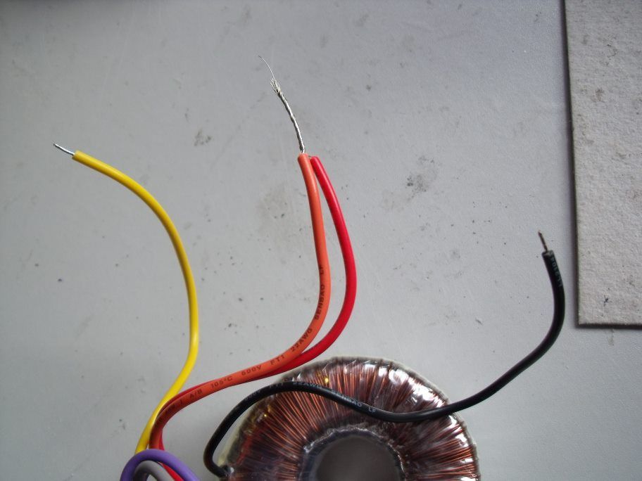 RED and ORANGE connected together. With your multimeter set on the AC range with RED and ORANGE connected together measure between YELLOW and BLACK.... you should get a reading of about 44 volts.  OK..... now measure between YELLOW and the connected RED and ORANGE wires....  You should get a reading of about 22 volts. Now measure between BLACK and the connected RED and ORANGE wires.... you should also get a reading of 22 volts. Sooooooooooo... you connect up thus: 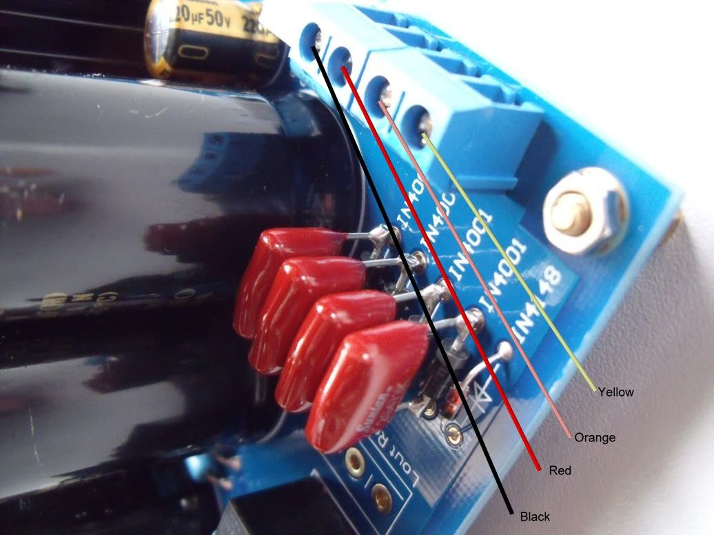 OR you can connect black and yellow the other way round.... they are both 18V. I hope this is better understood? Mike.
|
|
Deleted
Deleted Member
Posts: 0
|
Post by Deleted on Oct 20, 2010 13:30:57 GMT
OK ,
I am up and running, sounding good, but when i turn volume up past 12 o`clock there is a click from inside the output relay and sound from both channels stops, wind back to 12 and below, another click and its working again, so there is something not quiet right, any ideas would be welcome.
Mick.
PS. The minimum voltage i can get on VR4-VR5 is 1.5 volts, top limit.
|
|
Deleted
Deleted Member
Posts: 0
|
Post by Deleted on Oct 20, 2010 13:45:58 GMT
Are you sure the click is not the output relay ?
Is the DC output voltage adjusted close to the desired 0 mV for both channels ?
NOTE: the little pots are 25 turn potmeters that can be turned indefenitely.
When it reaches it's end point you'll hear faint 'clicks'.
These pots are usually set in 'mid position' from the factory.
If you have to turn the pot a lot of turns to reach the 0 mV output DC voltage you might need to match the input FET's.
This involves buying at least 10 to 20 pieces and a multimeter that can measure DCvoltage or DC current (and a set of instructions).
Matching input FETS could improve SQ !
With the amp powered off and you turn the volpot is there still a click at the 12'o clock position ?
If so... the volpot is defective but seems highly unlikely.
The sound stopping on both channels leads me to believe the relay is clicking because of a detected DC on the output.
Another way of finding out.
Do NOT connect anything to the input nor a headphone.
measure the DC voltage on the L out while turning up the vol pot (NO music !)
do the same with the left channel and post/PM what your findings are of both tests.
|
|
Deleted
Deleted Member
Posts: 0
|
Post by Deleted on Oct 20, 2010 15:12:25 GMT
HOW TO adjust the DC output voltage:This must be done before a headphone is attached to the amp and will (most likely) not be set properly by its default setting (these pots are usually at 50% of the resistance) First VR4 and VR5 must be adjusted as described in Mike's reply 122 on page 9 of this thread. After this has been set the DC output voltage must be set. These VR4 and VR5 must be set by adjusting VR4 and VR5 so that the 1.5k resistors R1,R2,R27and R28 (R1,R2 with VR4) (R27,R28 with VR5) have 1.3V over them. Measure this across these resistors and NOT related to ground like is needed for the DC output voltage adjustment ! VR4 and VR5 are 25 turn pots !! Mike wrote an excellent tutorial on this in the Panda Build thread, reply 7 page 1.. The easiest way is by connecting the black lead of a DC voltmeter on one of the grounds of the RCA socket or the output socket. The red lead must be connected to one of the resistors next to the relay (51k). The relay is the black box next to the output pins on the PCB. These resistors point in the same (length) direction next to this relay. Both are 51k. The one closest to the relay is the VR3 adjustment testpoint the one furthest from the relay is the VR2 adjustment testpoint. a note of CAUTION ! When performing these measurements make sure your testlead does not short the pad with the ground plane right next to the pad !! put the red lead of the DC voltmeter on the solder pad of the ((R43) resistor closest to the relay near the point where it says 51k on the PCB. Now adjust VR3 so there is 0mV (or as close as possible) everything within 10mV DC is O.K. It is a 25 turn pot so you might have to do several turns. Now the second channel. put the red lead of the DC voltmeter on the solder pad of the (R42) resistor furthest from the relay (next to the one closest) near the point where it says 51k on the PCB. Now adjust VR2 so there is 0mV (or as close as possible) everything within 10mV DC is O.K. IF this is O.K. connect your headphone and enjoy..  If not O.K....  If you need to do a lot of turns for the DC to get near 0mV or you can't reach it at all the input FETs are not matched at all. In this case you will need to mount a matched pair. a warning for this is issued both on the Panda site as I also did in the 2nd page of this thread. SQ may become better with well matched input FETs (same as with well matched input tubes/valves)
|
|
Deleted
Deleted Member
Posts: 0
|
Post by Deleted on Oct 20, 2010 20:45:06 GMT
hi Mick i have mine connected as mike's diagram, reading from left to right: pad 1 yellow 18v pad 2 orange 0v pad 3 red 18v pad 4 black 0v which seems to be the way that Sandyk is suggesting in his diagram also. anyone else who has finished their panda may want to correct me at this point (please) if I've got this wrong. i have to say that this arrangement meets my first criteria when amp building, IT WORKS . take care Thank you shaun, Fired it up, sounded great till you hit 1o`clock on the volume then both channels cut out but resume again at 12 o`clock. Now the left channel is dead, could not adjust the dc offset on this channel, but the right channel has been fine and easy to set to the perimeters given. Frans is on the case i will need to get another10 ohm resistor preferably a Dale, as one of mine needs replacing for starters, if anyone has a spare, its the one between the large caps and heat sinks there are 4 in total. Regards Mick. |
|
|
|
Post by PinkFloyd on Oct 20, 2010 20:57:59 GMT
Mick,
What's wrong with the 10ohm resistor??
|
|
|
|
Post by PinkFloyd on Oct 20, 2010 21:07:27 GMT
HOW TO adjust the DC output voltage:This must be done before a headphone is attached to the amp and will (most likely) not be set properly by its default setting (these pots are usually at 50% of the resistance) First VR4 and VR5 must be adjusted as described in Mike's reply 122 on page 9 of this thread. After this has been set the DC output voltage must be set. These VR4 and VR5 must be set by adjusting VR4 and VR5 so that the 1.5k resistors R1,R2,R27and R28 (R1,R2 with VR4) (R27,R28 with VR5) have 1.3V over them. Measure this across these resistors and NOT related to ground like is needed for the DC output voltage adjustment ! VR4 and VR5 are 25 turn pots !! The easiest way is by connecting the black lead of a DC voltmeter on one of the grounds of the RCA socket or the output socket. The red lead must be connected to one of the resistors next to the relay (51k). The relay is the black box next to the output pins on the PCB. These resistors point in the same (length) direction next to this relay. Both are 51k. The one closest to the relay is the VR3 adjustment testpoint the one furthest from the relay is the VR2 adjustment testpoint. a note of CAUTION ! When performing these measurements make sure your testlead does not short the pad with the ground plane right next to the pad !! put the red lead of the DC voltmeter on the solder pad of the ((R43) resistor closest to the relay near the point where it says 51k on the PCB. Now adjust VR3 so there is 0mV (or as close as possible) everything within 10mV DC is O.K. It is a 25 turn pot so you might have to do several turns. Now the second channel. put the red lead of the DC voltmeter on the solder pad of the (R42) resistor furthest from the relay (next to the one closest) near the point where it says 51k on the PCB. Now adjust VR2 so there is 0mV (or as close as possible) everything within 10mV DC is O.K. IF this is O.K. connect your headphone and enjoy.. If not O.K.... If you need to do a lot of turns for the DC to get near 0mV or you can't reach it at all the input FETs are not matched at all. In this case you will need to mount a matched pair. a warning for this is issued both on the Panda site as I also did in the 2nd page of this thread. SQ may become better with well matched input FETs (same as with well matched input tubes/valves) Frans, I disagree with your way of testing the DC offset as the "easiest". I think it's a lot easier to probe between ring and sleeve and tip and sleeve on the head socket itself as per www.rock-grotto.co.uk/dcoffset.htm Your way is absolutely 100% correct but it is not "easy" to get the probes into that small space.... a lot easier to just measure at the head socket in this application. I think we will have to "cherry pick" build instructions from this thread and put them in Mick's build thread (with pictures) I wouldn't like to have to trawl through pages and pages to find simple instructions.... I will get to work transferring a lot of important info in this thread over to rockgrotto.proboards.com/index.cgi?board=m&action=display&thread=5931 and will delete any crap from that thread that is not pertaining to actual "information" re: the Panda build. Mike. |
|
|
|
Post by clausdk on Oct 20, 2010 21:42:23 GMT
HOW TO adjust the DC output voltage:This must be done before a headphone is attached to the amp and will (most likely) not be set properly by its default setting (these pots are usually at 50% of the resistance) First VR4 and VR5 must be adjusted as described in Mike's reply 122 on page 9 of this thread. After this has been set the DC output voltage must be set. These VR4 and VR5 must be set by adjusting VR4 and VR5 so that the 1.5k resistors R1,R2,R27and R28 (R1,R2 with VR4) (R27,R28 with VR5) have 1.3V over them. Measure this across these resistors and NOT related to ground like is needed for the DC output voltage adjustment ! VR4 and VR5 are 25 turn pots !! The easiest way is by connecting the black lead of a DC voltmeter on one of the grounds of the RCA socket or the output socket. The red lead must be connected to one of the resistors next to the relay (51k). The relay is the black box next to the output pins on the PCB. These resistors point in the same (length) direction next to this relay. Both are 51k. The one closest to the relay is the VR3 adjustment testpoint the one furthest from the relay is the VR2 adjustment testpoint. a note of CAUTION ! When performing these measurements make sure your testlead does not short the pad with the ground plane right next to the pad !! put the red lead of the DC voltmeter on the solder pad of the ((R43) resistor closest to the relay near the point where it says 51k on the PCB. Now adjust VR3 so there is 0mV (or as close as possible) everything within 10mV DC is O.K. It is a 25 turn pot so you might have to do several turns. Now the second channel. put the red lead of the DC voltmeter on the solder pad of the (R42) resistor furthest from the relay (next to the one closest) near the point where it says 51k on the PCB. Now adjust VR2 so there is 0mV (or as close as possible) everything within 10mV DC is O.K. IF this is O.K. connect your headphone and enjoy.. My Panda is living proof that Frans' method works and a noob like me could do it |
|
|
|
Post by clausdk on Oct 20, 2010 21:44:13 GMT
Mick
I managed to repair a resistor with a broken leg, just soldered it toogether.
|
|
|
|
Post by PinkFloyd on Oct 20, 2010 22:06:10 GMT
HOW TO adjust the DC output voltage:This must be done before a headphone is attached to the amp and will (most likely) not be set properly by its default setting (these pots are usually at 50% of the resistance) First VR4 and VR5 must be adjusted as described in Mike's reply 122 on page 9 of this thread. After this has been set the DC output voltage must be set. These VR4 and VR5 must be set by adjusting VR4 and VR5 so that the 1.5k resistors R1,R2,R27and R28 (R1,R2 with VR4) (R27,R28 with VR5) have 1.3V over them. Measure this across these resistors and NOT related to ground like is needed for the DC output voltage adjustment ! VR4 and VR5 are 25 turn pots !! The easiest way is by connecting the black lead of a DC voltmeter on one of the grounds of the RCA socket or the output socket. The red lead must be connected to one of the resistors next to the relay (51k). The relay is the black box next to the output pins on the PCB. These resistors point in the same (length) direction next to this relay. Both are 51k. The one closest to the relay is the VR3 adjustment testpoint the one furthest from the relay is the VR2 adjustment testpoint. a note of CAUTION ! When performing these measurements make sure your testlead does not short the pad with the ground plane right next to the pad !! put the red lead of the DC voltmeter on the solder pad of the ((R43) resistor closest to the relay near the point where it says 51k on the PCB. Now adjust VR3 so there is 0mV (or as close as possible) everything within 10mV DC is O.K. It is a 25 turn pot so you might have to do several turns. Now the second channel. put the red lead of the DC voltmeter on the solder pad of the (R42) resistor furthest from the relay (next to the one closest) near the point where it says 51k on the PCB. Now adjust VR2 so there is 0mV (or as close as possible) everything within 10mV DC is O.K. IF this is O.K. connect your headphone and enjoy.. My Panda is living proof that Frans' method works and a noob like me could do it Claus, yes, I totally agree... Frans is 100% correct but it is NOT the easiest way to measure the offset as the space between the relay , resistors and other components is quite tight..... by far the "easiest" way is to measure between tip and sleeve and ring and sleeve on the headphone socket OR at the output pads on the PCB (measure between L/out and ground and R/out and ground. I ALWAYS measure at the headphone socket as this gives me assurance that there is 0mV at the headphone socket.... that's all I want to know and it also happens to be FACT that the head socket is the "easiest" place to probe in the Panda (plenty of room). Hope you are still enjoying the music Mike. |
|
Deleted
Deleted Member
Posts: 0
|
Post by Deleted on Oct 21, 2010 7:16:06 GMT
Its giving a 1.5ohm reading less then the others Mike, and there was smoke around it before the left channel died, right channel is fine at the moment.
Mick.
|
|
Deleted
Deleted Member
Posts: 0
|
Post by Deleted on Oct 21, 2010 7:21:21 GMT
If you try to measure the DC voltage at the output (which is easier, you won't make a short when shooting out with the testprobe) there is a snag.
IF the amp has a certain offset voltage that is higher then a certain value (around 1.2V) then the output relay will not be energised and thus the DC voltage (of both channels) will not be measurable on the output.
This is not hypothetical as Claus's amp had a higher initial value and Mick's amp was close to this value on one channel before the DC offset was adjusted.
On the indicated pads they will be available regardless of the state of the output relay.
hence my recommendation.
If the initial DC output is below 1.2V then Mikes method is better as there is less chance to create a fatal short.
This is the case if the relay clicks after a short time after start-up.
Another point is one of the middle pads of the 10 Ohm resistors between the cooling fins and the large caps, might be harder to access in a tight space and more difficult to see if you have the testporobes point in the right place.
Therefore I recommend the resistors next to the relay as these are easier to reach.
Also at this point be carefull to NOT create a short between the pad and the surrounding groundplane
The clearance is only a mm and a testprobe can easily penetrate the soldermask lacquer and create a short which might burn out 1 of the 10 Ohm resistors if there is a certain DC offset.
The UPC1237 IC not only makes the output relay enable possible after a predetermined time but also ensures the relay falls of quickly when the power is switched off and continuously senses the output of both amps for DC components.
The only downside this IC has it is not able to sense DC accurately when say one half is putting out +1V DC and the other half -1V DC.
In this case there is a lot of DC present and the amp should switch off but won't because the IC doesn't see it.
This might only be the case during initial start-up before the DC is adjusted.
a fault like this occuring IRL is extremely small so don't worry about this.
|
|
Deleted
Deleted Member
Posts: 0
|
Post by Deleted on Oct 21, 2010 17:12:17 GMT
hi mick
how's it going?
any news?
hope all is well
take care
|
|


 to make this confusing again I can give you the variations of windings that all lead up to the same outcome (a working amp)

