|
|
Post by tubehead on Oct 23, 2015 16:19:21 GMT
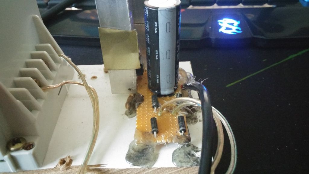
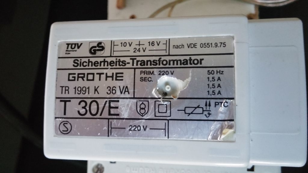
I found a nice 230v-24v transformer at work. took it home made a rectifier with 4 diodes folowed by a capacitor and then a 24v voltage regulator. Works like a charm and it really makes a difference in the sound. output looks flat on the scope too ! I am not surprised that it performs better now. It may even increase it's longevity by a considerable amount, as many units didn't last much longer than 12 months . Do you have any photos to show other Bravo users how you did it ?
Alex
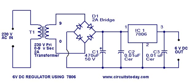
It's really ghetto i should make a case for it but here it is in al its glory. It's basically this minus the two small caps and i have in the place of the ic a voltage regulator L78024CV. My smoothing capacitor is a 10.000 micro farad 35v elna rjd cap. thats it'    It's cheap and very effective |
|
Deleted
Deleted Member
Posts: 0
|
Post by Deleted on Oct 23, 2015 20:44:46 GMT
Good call with removing the ceramic capacitors. These days it's a no-no to use very low ESR capacitors directly at the output of a typical voltage regulator such as the 78xx and 79xx.
|
|
|
|
Post by cpcustoms66 on Oct 24, 2015 23:19:03 GMT
Would it help the switching power supply noise if I made a rectifier with 4 diodes in line with the power cable?
|
|
Deleted
Deleted Member
Posts: 0
|
Post by Deleted on Oct 24, 2015 23:50:47 GMT
Would it help the switching power supply noise if I made a rectifier with 4 diodes in line with the power cable? From Page 1 of this thread.
|
|
|
|
Post by cpcustoms66 on Oct 25, 2015 13:06:27 GMT
Thanks SandyK! now to just find the correct value Inductor
|
|
|
|
Post by tubehead on Oct 25, 2015 16:13:38 GMT
Thanks SandyK! now to just find the correct value Inductor Just find a transformer the amp will sound much better with a linear power supply. |
|
|
|
Post by cpcustoms66 on Nov 3, 2015 2:57:24 GMT
cant find any 24 volt linear power supplies for less than around $150, anyone know of any cheaper Linear solutions?
|
|
jc
Fully Modded
Posts: 5,417 
|
Post by jc on Nov 3, 2015 12:02:40 GMT
I found this in just moments.  |
|
|
|
Post by PinkFloyd on Nov 3, 2015 21:59:12 GMT
I found this in just moments.  27 seconds. |
|
|
|
Post by cpcustoms66 on Nov 4, 2015 23:19:12 GMT
It is only 1.04 amps, would that be alright? I figured I would try to match the 1.5 amps of the original power supply
|
|
|
|
Post by tubehead on Nov 6, 2015 21:50:08 GMT
It is only 1.04 amps, would that be alright? I figured I would try to match the 1.5 amps of the original power supply Try to find 1.5/2 amps just to be safe. |
|
|
|
Post by rudy123 on Nov 9, 2015 16:10:44 GMT
Hi, im looking to build this amp for a project i am building for my HNC. i have found various information regarding the parts i need but not found a full list. is there anyone on here that would be able to direct me to a full parts list, or maybe you know them all. i have searched the internet for weeks but cant seem to find a thing! thanks in advance, all help is appreciated  |
|
|
|
Post by tubehead on Nov 20, 2015 17:46:45 GMT
Just go back to page 1 and go through the tread and take a pen and paper to note the parts. i used elna 2x re3 1000uf 25 1x elna rjd 10000uf 35v 2xirl530 custom heatsinks custom power supply Philips 6922 tube provided by the boss here mike !. Note i have the v1. but these mods are pretty much the same. only for the 12au7 v2 you got to do the crosstalk mod Hi, im looking to build this amp for a project i am building for my HNC. i have found various information regarding the parts i need but not found a full list. is there anyone on here that would be able to direct me to a full parts list, or maybe you know them all. i have searched the internet for weeks but cant seem to find a thing! thanks in advance, all help is appreciated  |
|
|
|
Post by captainpip on Jan 22, 2016 20:42:45 GMT
Just replaced the big capacitor with a 4700uF 35v nichion, It seems I managed to kill the red LED somehow in doing this. Will this cause any problems? I don't mind living without it, it was a bit too bright for my taste anyway.
Edit: Read through the thread and was reading people say it is needed. Is it possible to just put a wire across it to fix the situation or does the LED provide something?
|
|
Deleted
Deleted Member
Posts: 0
|
Post by Deleted on Jan 23, 2016 10:40:22 GMT
Just replaced the big capacitor with a 4700uF 35v nichion, It seems I managed to kill the red LED somehow in doing this. Will this cause any problems? I don't mind living without it, it was a bit too bright for my taste anyway. Edit: Read through the thread and was reading people say it is needed. Is it possible to just put a wire across it to fix the situation or does the LED provide something? Is it working O.K. without the red LED ? In the schematic I looked at it didn't appear to do anything more than enable the Blue LED to illuminate, as it is in series with it.
|
|
|
|
Post by captainpip on Jan 23, 2016 11:54:14 GMT
Just replaced the big capacitor with a 4700uF 35v nichion, It seems I managed to kill the red LED somehow in doing this. Will this cause any problems? I don't mind living without it, it was a bit too bright for my taste anyway. Edit: Read through the thread and was reading people say it is needed. Is it possible to just put a wire across it to fix the situation or does the LED provide something? Is it working O.K. without the red LED ? In the schematic I looked at it didn't appear to do anything more than enable the Blue LED to illuminate, as it is in series with it.
After listening to it more I figured out it was running a lot quieter than before, had to crank up the volume to get the same output. Ran down to the shop and picked up some LED's they only had yellow with a through voltage of 2.1 so I stuffed that in and it appears the LED is integral to the circuit in some way since it picked back up with that. Not sure if it'll be bad since I read earlier in the thread the stock red LED has a through volt of 1.8, so far it's worked fine all day though. It's coming along quite nicely though I figure, this thing has some great sound when you put a bit of work into it.  |
|
Deleted
Deleted Member
Posts: 0
|
Post by Deleted on Jan 23, 2016 12:20:09 GMT
O.K. In this case the schematic is badly drawn as I am used to a connection being shown as a dot at that point.
The drop across the red LED sets the emitter current of transistor Q4, By replacing the red LED with the yellow LED you have increased the anode current of the valve by a small amount. Q4s emitter current is it's VBE ( voltage Base to Emitter) of typically a little over 600mV subtracted from the forward voltage of the LED. With the Yellow LED you will be dropping 2.1V - 600mV = 1.5V across the 3Kohm emitter resistor. You can work out the actual emitter current and thereby the tube's Anode current with both the red LED and the Yellow LED using Ohms law.
Given that these amplifiers have a poor longevity record, I would try to obtain another red LED.
Alex
|
|
|
|
Post by PinkFloyd on Jan 23, 2016 21:46:39 GMT
O.K. In this case the schematic is badly drawn as I am used to a connection being shown as a dot at that point. The drop across the red LED sets the emitter current of transistor Q4, By replacing the red LED with the yellow LED you have increased the anode current of the valve by a small amount. Q4s emitter current is it's VBE ( voltage Base to Emitter) of typically a little over 600mV subtracted from the forward voltage of the LED. With the Yellow LED you will be dropping 2.1V - 600mV = 1.5V across the 3Kohm emitter resistor. You can work out the actual emitter current and thereby the tube's Anode current with both the red LED and the Yellow LED using Ohms law. Given that these amplifiers have a poor longevity record, I would try to obtain another red LED. Alex I love it Alex!  You are the master! A replacement red LED is the order of the day. Mike. |
|
|
|
Post by filippomeucci on Feb 13, 2016 18:26:03 GMT
Dears, I would to ask for support... I tried to change tube (a Chinese 12AU7 for a National US 12AU7A). however the last tube, which is supposed to be much better it is saturating. I see there is a 2k pot on the cathode. Is that that I have to check and set ? How should I proceed ? I am new in the tube electronics, and any help would be really appreciated !! I tried to find out some clues on the web but I did not find anyone. Thank you ! Best Filippo |
|
|
|
Post by cwwright on Mar 11, 2016 12:53:43 GMT
I have a V2 with the groove tube with no other mods yet. My infrared thermometer shows even heating of the components between the left and right channels except for the FETs. One side runs about 110 while the other reaches 150f at idle. With all precision resistors in the design, I am surprised there is such a difference between the channels. Any thoughts would be welcome.
|
|
|
|
Post by lemondixon on Mar 30, 2016 16:35:33 GMT
I've searched high and low trying to find an answer online, but so far this mods thread was the closest in terms of relevance and these latest comments were only late January (some others are years and years out of date).
Basically, I've bought a used v2 unit on eBay to play around with but it's faulty and my electronics knowledge is pretty flaky and haven't done any of this since I did my A-Levels before Uni back in the early '90s. I have a multimeter borrowed from a mate of mine and am struggling to know how and where to test it without knackering it up.
The problem is that there's no sound coming out the jack on the left channel, and I was trying to figure out if it is (a) fault at the jack, (b) one of the triodes in the tube has gone, or (c) if it's something to do with a major biasing imbalance. The guy on eBay gave me a full refund but told me to keep it, so I figured it might be worth playing with to try and fix it or modify it in the process; but not if the whole thing is completely shagged!
Here's what I've checked / found so far:
1. Pushing the (male) 1/4" jack 2/3rds of the way in (so the tip is not at the back in it's proper place) gives sound in both headphones, but this is just the right channel duplicated in both cans. Tracks which pan all the way left show this up;
2. The sound seems the same if you swap left/right RCA input around, and if you leave only the left RCA connected you still get some sound but much quieter and still only in the right hand headphone - I'm guessing this is the crosstalk or something?
3. Measuring the voltages for the channel bias (there's no trim pots on this version of course) shows a massive discrepancy - The right channel is 16.1V whereas the left channel is only 10.1V
On this basis, does this rule out the tube being completely knackered (even though the bias is way off) as would there be any voltage on the left if the break in the chain was the triode feeding the left channel (or have I got this wrong)?
Obviously I can't fix the bias without modding the unit anyhow, but wasn't sure if the unit was knackered it was worth getting a new tube for it even if the replacement was properly matched so the output on both channels were more like they should be?
Would be a shame to just throw it in the bin if there is something I can do to test it to see if it's worth repairing. Any ideas?
Thanks for your patience and input.
Cheers,
Steve
|
|
Deleted
Deleted Member
Posts: 0
|
Post by Deleted on Mar 30, 2016 20:14:44 GMT
IMHO, they are not worth repairing. Many of these units die just over 12 months of use due to poor thermal design. At the very least you will also have to replace the electrolytic capacitors close to the valves as well, and there is also a high probability that it will fail again a little over 12 months later. Electronics Engineer Frans deGruitjer addressed many of these short comings in his own designs, which were also further improved in every respect, including performance.
If you want a good quality valve based amplifier that will continue to perform for many years, then I suggest that you look at the designs and kits from Jeremy in DIY Audio Heaven that were designed by Frans. (Solderdude).
Alex |
|
|
|
Post by PinkFloyd on Mar 30, 2016 21:24:47 GMT
IMHO, they are not worth repairing. Many of these units die just over 12 months of use due to poor thermal design. At the very least you will also have to replace the electrolytic capacitors close to the valves as well, and there is also a high probability that it will fail again a little over 12 months later. Electronics Engineer Frans deGruitjer addressed many of these short comings in his own designs, which were also further improved in every respect, including performance.
If you want a good quality valve based amplifier that will continue to perform for many years, then I suggest that you look at the designs and kits from Jeremy in DIY Audio Heaven that were designed by Frans. (Solderdude).
Alex Totally agree with Alex on this one, Frans know his onions and he is the go to man for these types of open frame RFI fest types of amps....... he has got them down to a fine art. Mike. |
|
|
|
Post by infernet on Apr 19, 2016 7:28:02 GMT
Hi everyone, I'm new here! After reading your posts I decided to try and improve my bravo audio... I made this mods : - cap input swap with nichicon 3300uf 35v
- cap output swap with nichicon 2200uf 35v
- swap IRF630 with IRL510
- swap LM317 with LM317AT
So... I switched it on and the sound was terrible! dirty, with no bass ... I wonder what's happened!!  solders seems to be ok... would you please help me? some photos here:     THANKS A LOT!!!! |
|
|
|
Post by knottydreadbr on Apr 23, 2016 19:24:15 GMT
Hello. Are all those upgrades suitable for Bravo V3 (equalizer version)? Can I switch the IRF630 to IRF510 on it? Thanks.
|
|