|
|
Post by attilio on Mar 22, 2010 11:11:20 GMT
Surely you have to establish what is wrong, before you can improve them?
attilio
|
|
Deleted
Deleted Member
Posts: 0
|
Post by Deleted on Mar 22, 2010 11:21:18 GMT
temp measurements after about 30 mins @ 16 Volt bias
FETS = 71oC
LM317's 75oC
cap close to LM317 = 47oC
cap furtherst from LM317 = 30oC
PS cap = 40oC
temps will be lower when a gentle breeze runs past it.
big difference in output cap temperatures.
All caps are rated for max 85oC.
so 1 cap 30oC other one 47oC that makes a lot of sense to me...
of coarse this is in G1 the G2 has the caps at equal distances so that problem was 'solved' with another PCB design.
From a technical point of view I really don't like the temperatures of the electronic parts.
The PCB will suffer heat damage over time and FET/LM317 may 'unsolder' themselves over time.
Watch those solder joints/PCB is my advice.
I agree with Attilio... First you find out what needs improving... then you do something about it.
Seems logical (I sound like spock now)
|
|
|
|
Post by PinkFloyd on Mar 22, 2010 11:26:52 GMT
Frans, you are correct... the crosstalk is HORRENDOUS  |
|
Deleted
Deleted Member
Posts: 0
|
Post by Deleted on Mar 22, 2010 11:28:49 GMT
I haven't tried it myself but at what volume does it become annoying ?
There should be improvement with higher bias settings.
Please confirm sonically as I don't have a HP on my test bench at work..
If it stays within it's linear state (at lower listening levels) the crosstalk only affects the stereo image/placement of instruments.
It becomes problematic as soon as the LM317's threshold for proper operation is reached AND 1 channel is active (Stereo)
When both channels are driven at the same time it might be less of a problem..
haven't done those measurements as I don't have a good THD analyser available at this time.
|
|
Deleted
Deleted Member
Posts: 0
|
Post by Deleted on Mar 22, 2010 11:43:58 GMT
I agree, but it doesn't need to be so brutally honest that it further upsets the members that own them, and changes RG into 2 warring camps.
This is a highly emotive issue for many,especially our good friend Mike, who almost certainly is rather fragile after Rick's untimely death.
I feel sure that if anybody requires indepth information that all they need to do is to send a PM to Frans.
This is supposed to be a fun little amplifier, not a megabuck amplifier where such close scrutiny would be more warranted.
I have already made my feelings very clear about the lack of QC with these amplifiers. That is very dissapointing.
I also look forward to a further report from Leo, who found it easier to listen to than the DouDou amplifier, despite all it's limitations.
SandyK (Alex)
|
|
Deleted
Deleted Member
Posts: 0
|
Post by Deleted on Mar 22, 2010 11:51:26 GMT
If Alex is right I will only report my findings after I have been PM'd.
As I have stated from the start this amp got launched in the Grotto.
If it sounds good to you then just use it.. eventhough the design is not very ... uhmmm can't say that anymore..
|
|
Deleted
Deleted Member
Posts: 0
|
Post by Deleted on Mar 22, 2010 12:06:41 GMT
If Alex is right I will only report my findings after I have been PM'd. As I have stated from the start this amp got launched in the Grotto. If it sounds good to you then just use it.. eventhough the design is not very ... uhmmm can't say that anymore.. Frans A few people saw the Forum header previously. This subject,as well as several others, has already become so divisive that Mike felt that this was no longer his forum,and wanted out. I have no desire to censor yours, or anybody else's posts, but I do wish to try and keep RG the friendly place that everybody loves. Let's all step back for a while, and hope that Mike reconsiders his earlier decision. I love this place and it's members, and do not wish to see it disappear. SandyK (Alex) |
|
|
|
Post by MaN227 on Mar 22, 2010 12:31:54 GMT
maybe the forum could have a donater tag that goes under the members avatar? maybe more would be inclined to donate and feel they have something to show for it. and in turn may help make Mike feel that it IS worth keeping it up and running. I have donated once and will donate again if that is what needs to happen. I'm still totally lost in the "technical' talking of stuff, but I pick up bits and pieces here and there. and above that I like the folks I am getting to know in here. now a bit more on topic.... something I find myself wondering about . modding and changes, and why I never read about them being done with the G1? but the G2 comes along and its mod city.... just curious , so please no one take offense. was the G1 that good with its parts selection? and the G2 not ? I guess why I find myself wondering so much about it, is the G2 is the newer version, and supposedly the improved version. or is it the potential for greatness is seen in the G2 where it was not with the G1?     inquiring minds want to know.  |
|
Deleted
Deleted Member
Posts: 0
|
Post by Deleted on Mar 22, 2010 12:49:12 GMT
In this case I will not publish my findings anymore in regards to the G1. I tend give Mike MUCH more credit than that and feel that he too would be interested in tests and possible improvements that may come from this research. I prefer to let him speak for himself though.  If my input is not desired then I'll leave it be ... Peter and Mike nor anybody else that likes these amps are/nor will be portraited as idiots by me... in fact I am more interested in WHY this much liked amp performs good sonically and bad on a test bench. That's the real puzzle... I have been posting in the wrong thread because my measurements are related to G1.. my bad. In essence the G2 is similar but with some small changes. |
|
leo
Been here a while!  Team wtf is it?
Posts: 3,638
|
Post by leo on Mar 22, 2010 15:20:59 GMT
Been a little busy lately (which is why I've been quiet) so not had time to stick the G2 on the scope or do any proper tests yet, I'm actually glad Mike suggested I keep the G2 for a little while so it gives more time with it Anyway as I've mentioned before my hearing is pretty sensitive, I can't listen to music through any headphones loud so tend to always have the vol set which would probably too low for a lot of folks. Going through a wider range of music with the G2 I did notice some light distortion (mainly left channel) with some busy music, most noticeable with piano, I thought it maybe just a crappy valve, I was going to wait until I'd tried the E88CC gold pin Mullard before commenting. I've just read Frans post regarding the crosstalk, out of interest I unplugged the left input and played the same busy piano tracks but now just feeding the right input. I had a listen to the left headphone and could hear low level music which is distorted (that'll be the distortion I've noticed playing in stereo) , it actually sounds like rustling tracing paper , crackling  I'll try highering the anode voltages tonight, at the moment its still 12v L&R I'll also do some temp measurements I still find theres a bloom added to the mids and upper bass, the valve replacement should alter things so I'll try that as soon as its here. Its best to go over everything first before giving a proper opinion  |
|
leo
Been here a while!  Team wtf is it?
Posts: 3,638
|
Post by leo on Mar 22, 2010 15:36:35 GMT
BTW I didn't have to crank it up loud to hear the distortion using just the right input, about 10 o'clock on the pot and you can hear it through the left ear piece, it sounds like the music is overblown
Also as already mentioned this varies depending on the music/track used
|
|
leo
Been here a while!  Team wtf is it?
Posts: 3,638
|
Post by leo on Mar 22, 2010 17:52:42 GMT
Ok, quickly adjusted bias L&R to 15v, the heater voltage obviously goes up too (now at 6.34v) At my listening setting the distortion is greatly reduced, the distortion starts getting more noticeable when the vol is increased but this is too loud for me personally anyway so its not a problem at my setting. So if your amp crackles distorts when playing music at your favoured vol setting its worth increasing that bias, if you get no problems at the standard 12v then its the simple case of don't worry  The cross talk is still there, not quite as bad but still there, you may not even notice it in normal use ;D Will measure the temps later |
|
Deleted
Deleted Member
Posts: 0
|
Post by Deleted on Mar 22, 2010 18:13:00 GMT
Looking at one of the spin off sites from attilio7 link. Some of Leos early points look, to my "sabe nada" eyes, to be addressed in the more original design (closer to the Sijosae he spoke of)... 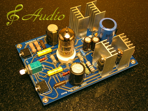 More details here |
|
Deleted
Deleted Member
Posts: 0
|
Post by Deleted on Mar 22, 2010 18:44:40 GMT
Hi Guys,
I'm back on line now after Sky.com stopped me accessing the forum for a couple of days or so. I've had a quick squint through the threads but if I've missed anything please forgive me.
Thanks to Mike I checked the bias of my valve - to my surprise I got 14.25v on both but contrary to Mike's pics the red lead went to the solder spots and the black lead went to the volume knob - problem? I have reset them to a gnat's under 13v but, TBH, my cloth ears failed to perceive any changes. I've just checked them again a good hour later and they have not changed.
Another thing I've noticed is that, before I started messing, both the red and blue LEDs were lit but after messing only the blue one comes on - problem? What does the red LED indicate?
One thing I did that might help others is, with the judicious use of a small electric drill I have drilled small holes in the bottom sheet of perspex opposite the solder spots used to check the bias - now there is no need to remove the bottom plate and, as a bonus, it makes it easier to hold the multi-meter probe in place.
Another thing I did, this time with the judicious use of a small (rat tale ?) file, is to file a couple of small slots in the top perspex cover at the 3 and 9 o'clock position on the large valve hole. This allows the bias adjustment to be made from the top. I have not patented either of these actions so you may copy them free of charge if you feel the need, and this also applies to Peter also ;D .
Both these actions are best done after removal from the amp ;D .
Cheers,
Dave.
|
|
Deleted
Deleted Member
Posts: 0
|
Post by Deleted on Mar 22, 2010 19:34:20 GMT
Excellent idea Dave... the extra holes.  The LED's indicate nothing..  the blue LED is there PURELY for decorative reasons. If you don't like it and want it off you can just solder a piece of wire over it. You don't have to take it out... just short it.  You can also replace it with a green, orange, yellow, red, purple or even white LED if you prefer that.  Just make sure it is a high efficiency type. the red LED has a specific function in this amp and is used to provide a bias voltage for the 2 CCS (constant current sources) in the anode circuits of the tube. A red LED has a specific voltage drop that is reasonably stable. The voltage drop is dependent on color and current and will be about 1.8 Volts in this case. It does vary a bit over the temperature range but the transistors Base-Emitter voltage does too and in the same direction so compensates a bit. The transistor B-E junction has a voltage drop of about 0.5 to 0.55 Volts for those that are interested. You can't take the red LED out or replace it with another color LED because each color has a different voltage drop and thus the anode current will vary too (and therefore the anode voltage also) if you would put in another color LED. You can check if the voltage across the LED is around 1.8 volts (give or take a bit) to see if it is working O.K. It does not matter how bright this LED lights up because that is also dependent on the efficiency of the LED. It can do it's work already when it barely lights up. Hope this clarifies a bit about the red and blue LED and the function of the red LED If in the unlikely event you want this LED out to (see no reason for it) then I suggest you paint it black or cover it in another way. You can also replace it by 3 or 4 small signal silicon diodes in series.  |
|
Deleted
Deleted Member
Posts: 0
|
Post by Deleted on Mar 22, 2010 20:03:56 GMT
Hi Frans,
Thanks for taking the time to explain that - a numptie like me tends to worry when a light comes on, then you do a bit of tweaking and it doesn't come on again - now what have I done wrong? I can't say that I followed it all but I get the general picture.
The main reason for posting now is that I think I may have mislead readers with my comments about the lack of any improvement after adjusting the bias. I had just confirmed, after one hour, that the bias had remained at circa 12.95v on each channel when my chef (SWMBO) called me for my meal so I only listened to it for a few seconds when I posted "no change". I left it running over the meal and came back an hour or so later and now I can notice the change for the better. certainly the bass is better, perhaps extending a touch lower, but definitely tauter - I get a much more 'sonic picture' of the bass string being plucked and twanging as it decays.
BTW my cheapy 24v Linear PSU has not arrived as expected today so I can't advise anything on that front yet.
Cheers,
Dave.
|
|
|
|
Post by PinkFloyd on Mar 22, 2010 22:12:17 GMT
Hi Frans, I'm just a bit pissed off at the moment (with life in general) and seem to be jumping down people's throats for no apparant reason  Hell man, the Indeed / Bravo / MiriDIY amps are FAR from perfect and leave a lot to be desired in quite a few areas.... of COURSE you can comment on the technical aspects of these amps (I welcome it).... it helps cut through the bullshit about "PURE" class A, parking 85C caps right next door to a furnace to "make them sound better" and all the other AD copy crap  Remember though.... they are not "High-end" amps and to dissect a £50 amp that sounds half decent and then wonder why it doesn't measure up to "exacting standards".... of course it doesn't, it costs the price of a "meal out" (I prefer to eat at home BTW!) and doesn't claim to be anything other than a very nice listen for the money, and it IS a very nice listen.... no doubting that. You mentioned the pot being Linear.... Well..... I decided to remove the 20K pot on the Indeed G1 today.... I went to pull the knob off and: 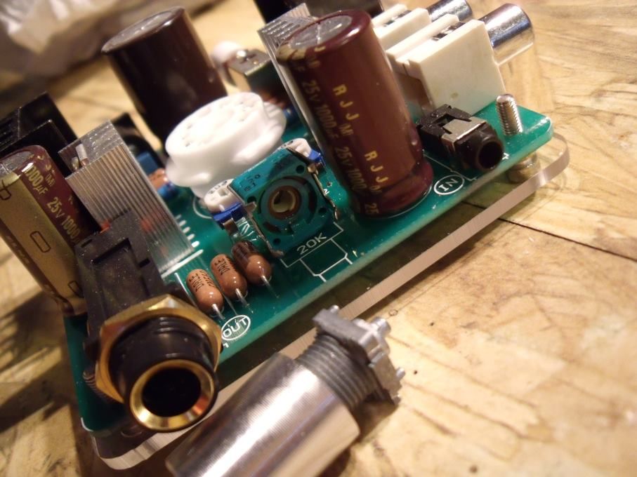  Now, if that's a genuine ALPS pot I will eat my hat! I am not a "bodybuilder" and just tugged gently to get the knob off.... the damned thing fell apart! Fortunately I have tons of old "pulls" out of MF amps so stuck one of them in: 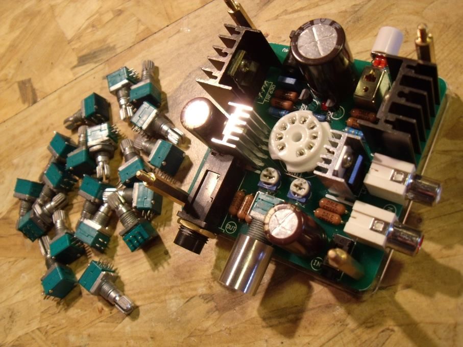 Not sure it's any "better".... it still goes loud pretty fast. The "stock" pot was a 20K type, I have fitted a 50K log type but will try a 20K and 10K "genuine" ALPS type tomorrow.... I'm lucky cause I have a couple of hundred of these so can match one up to "perfection"..... I reckon 10K will give lower noise, what do you reckon? Again..... related to the G1..... the power cap is 25V / 2200uF (the Bravo is 25V / 6800uF).... as Leo (and others) have pointed out, 25V is a bit close to the bone and 35V a lot more desirable. I also think 2200uF / 6800uF is a bit measly so had a look round my cap stash and found a box of 10,000uF / 35V Panasonic snap in 105C types.... I measured them up and they were a PERFECT fit (sideways) as long as you "skinned" them..... I araldited one into position and the plexiglass clamped down on top to provide a PERFECT fit  .... the plexiglass "just" makes contact with the cap ensuring a bullet proof fix (epoxy on base / plexiglass clamp on top) : 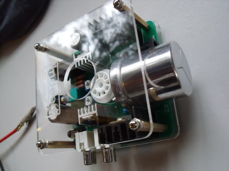 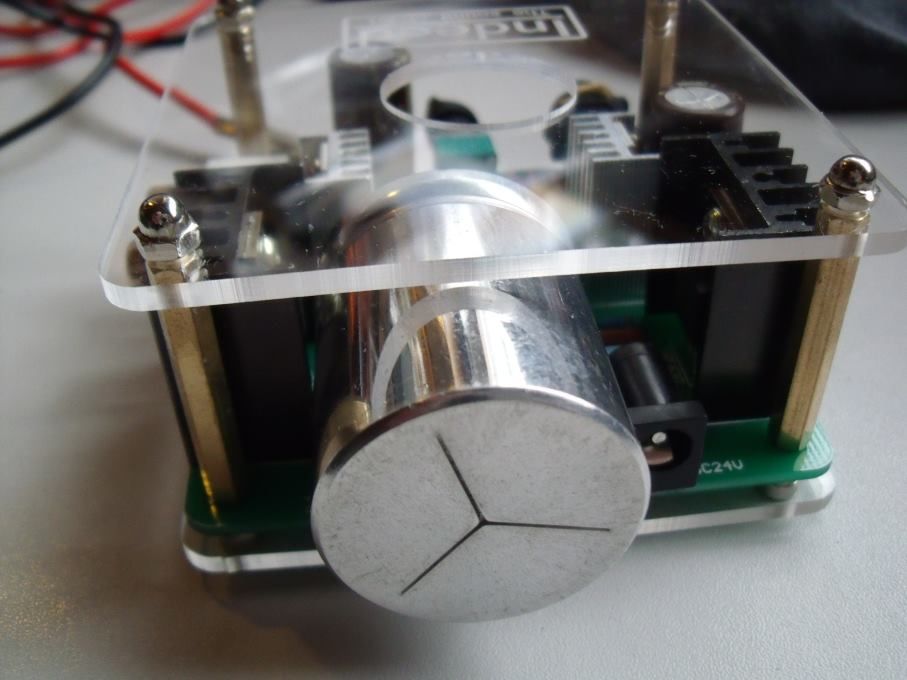 Leads up to the cap terminals are SHORT as possible and are PTFE insulated (silver plated copper strands)....... I will be going back under the bonnet of the G1 tomorrow (Tuesday, my one day "off" per week where I spend doing "more" soldering but, this time, for personal pleasure  ) The IRF630 DO roll off the highs..... I am "as we speak" doing a comparo of the Bravo (which I have fitted IRF510 into) and the Indeed (630) sounds decidedly "compromised" in the HF region .... to MY ears the IRF510 are, by far, the better choice of MOSFETS...... I hope Leo tries different MOSFETS out in his sample.... by the way Leo, nobody is beating my door down to try the evaluation G2 so it's yours to keep indefinitely... do what you will with it  Not a lot more we can "do" with this design apart from changing the Mosfets, improving the heatsinks, fitting 105C caps, slamming a decent PSU onto it, fitting higher capacitance coupling / PSU caps and housing the entire shebang in a Faraday cage...... that would all cost "money" and it would still "measure" as CRAP on an oscilloscope.... (mine went off the scale when it "measured" the G1  )...... We could just "listen" to the music though... at the end of the day, that's what counts.... if it sounds good it IS good (distortion and all) You tell me of one LIVE concert you've been to that is "distortion free".... I can confidently call you a Liar! Enjoy the MUSIC! Mike. |
|
Deleted
Deleted Member
Posts: 0
|
Post by Deleted on Mar 22, 2010 22:56:11 GMT
That is one HUGE capacitor.
I bet if you connect it the wrong way it can blow the amp halfway to the moon !
About the pot.
I noticed when it was at max position and I set the tone generator so that the input was far from clipping and turned the pot halfway the output voltage halved to.
This indicates a lin potmeter.
A log potmeter would have about 1/10th of the full output voltage in that setting.
If it has a 'B' on it (in the type number) it's Lin
If it has an 'A' on it it is Logarithmic
a simple solution to sort of 'mimic' the response of a log type is by mounting 2 resistors of around 2k2 from the center tap to ground (when a 20k pot is used) this should give a somewhat easier adjustment at lower listening levels.
for a 10 k pot a 1.2k res for a 50 k pot a 5.6k res.
In theory 10k should give lower noise floor in microphone amps and MC amps for example.
The noise generated by the tube will be much higher than noise generated by the resistance value, also there should be no DC components that helps too.
10k wouldn't hurt anything in fact it is better against picking up HF pollution (about 3dB)
You are right about the money thing.
It is cheap, cute ... hell I like it myself and I don't even like tubes but others do and want to mod it just for the fun of it.
I am more a hands on type of guy with just different experiences as you and have done some crazy experiments..
You are also right on the listening part.. that's what it is for.
Ian had troubles (rustling startup noises that I think eminate from the 25V PSU cap) with his amp and would like the blue lights out and a lower gain.
I would like a mod to really autobias it regardless of the used tube and the bias would never be 'off' again.
So I will be repairing it's faults over the coming weeks and try to come up with an easy mod for this that can be applied so it will measure better.
Ian can then confirm if it sounds better too as he has a 'music oriented brain' and I have not.
Hope he likes what I did to it.
In order to mod it I would need to measure where it goes wrong and highly suspected the LM317 setting with the common filament so started there and voila...
Now this can be solved by altering the amp's footprint so it can use ECC81,82,83 and have each filament of the tube (it is split at pin 9) to it's own LM317.
No more crosstalk distortion !!!
Needs modding of the PCB cutting copper, rerouting wiring e.t.c. but will solve it.
So I will be scrutinizing the amp before I will make this one so it will perform ON the testbench AND in the musical sense.
It is a minimalistic design and cheap that's what triggered me (like the HD681) and will continue till I know all there is to know about it.
I sincerely hope your angre to the world goes away.
Won't be easy fighting this...
Yep most concerts are one big bag of distortion.
In this case it is all about the experience, emotion, involvement, crowd, the band, the songs and the amplification is only a necessity.
At home I prefer to listen distortion free and have devoted my life to this (sort off) and want/like to do this at absolute minimum costs !
take care Mike..
Health is everything
(yes Alex... I know I need to watch my own situation too)
|
|
Deleted
Deleted Member
Posts: 0
|
Post by Deleted on Mar 22, 2010 23:15:57 GMT
Hi Frans, As a VERY satisfied customer can I place my name on your list of potential customers as, when and if you decide to offer your magic dust sprinkling on the G2 to forum members? If you can work the same sort of magic on the G2 that you did on my HD681s, and I have no doubts that you can  , the G2 will be a little marvel indeed. Thanks in anticipation, Dave. |
|
Deleted
Deleted Member
Posts: 0
|
Post by Deleted on Mar 22, 2010 23:22:13 GMT
|
|
|
|
Post by PinkFloyd on Mar 22, 2010 23:37:40 GMT
Mick..... leave me with it a couple more days...... you haven't seen anything yet   |
|
|
|
Post by MaN227 on Mar 23, 2010 4:15:30 GMT
so the alps pot is NOT an alps pot ? did i read that correctly? if i did read that correctly that does not make me feel all warm and fuzzy about all the other parts being what they are claimed to be, not in the least  |
|
leo
Been here a while!  Team wtf is it?
Posts: 3,638
|
Post by leo on Mar 23, 2010 20:50:54 GMT
Mick..... leave me with it a couple more days...... you haven't seen anything yet   Bring it on Pinkster  I fitted the IRF510's today, those screws was very tight, I removed the LM317's first to allow easier access to the IRF610 screws. Certainly has altered the sound, bit more in the high's now and a bit less bloom, there does seem to be less low end but it maybe just tighter. A cap change or alternative valve may help the bass. Its only early days but so far I prefer it with the IRF510's |
|
|
|
Post by PinkFloyd on Mar 23, 2010 23:32:02 GMT
so the alps pot is NOT an alps pot ? did i read that correctly? if i did read that correctly that does not make me feel all warm and fuzzy about all the other parts being what they are claimed to be, not in the least  Sorry Chaz, I should have said "it didn't seem as robust as other ALPS pots I have used"..... It could well be an ALPS pot but I have never, personally, witnessed one coming apart when I've pulled the knob off ;D I, also, haven't seen them available with the metal shroud.... maybe I haven't looked hard enough....... That tinny little shroud and the 4 clasps is all that holds this pot together.... most ALPS pots I have seen have rods running through them (to hold them together) and NO WAY are you going to seperate them pulling a knob off..... The pot "itself" does the job very nicely and should last many years (unless you want to pull the knob off and then things may go pearshaped  ) I am not saying it's NOT a genuine ALPS, I'm just saying that I haven't seen one like this before. The rest of the components look totally genuine.... If they were fake then the power cap would be stamped "Black Gate" or some such name..... it's a "no name" cap and this suggests that the rest of the parts on the board are of good pedigree ..... if they are going to "fake it" then may as well fake the lot ;D Nope, to my eyes (and ears) the parts are the real deal (what do you think Leo?) it's just that pot that looks a bit iffy to my eyes. Mike. |
|
|
|
Post by PinkFloyd on Mar 23, 2010 23:50:07 GMT
Mick..... leave me with it a couple more days...... you haven't seen anything yet   Bring it on Pinkster  I fitted the IRF510's today, those screws was very tight, I removed the LM317's first to allow easier access to the IRF610 screws. Certainly has altered the sound, bit more in the high's now and a bit less bloom, there does seem to be less low end but it maybe just tighter. A cap change or alternative valve may help the bass. Its only early days but so far I prefer it with the IRF510's Yeh mate, A bit more "sparkle" to the sound.... the 630's definitely "subdue" the HF energy..... give the 510's a few days to cook..... Mike. |
|