Deleted
Deleted Member
Posts: 0
|
Post by Deleted on May 1, 2010 18:36:11 GMT
Ian, I have just made an Ali base plate for mine before i send it off to Frans. looking at your photo`s i need to make some spacing pillars to provide the gap between base plate and pcb, can you tell me what that gap is in mm please, looks about 10mm. Thanks. Mick. Mick, Its 15mm. From bottom of top plate to bottom of the bottom blate so allowing for thickness the pillars are 12mm. Ian |
|
Deleted
Deleted Member
Posts: 0
|
Post by Deleted on May 1, 2010 19:03:52 GMT
Ian,
Can I ask you if there are any other connections between metal base plate and PCB/components other than the 4 corner pillars? Common sense says that there should be and your pics show evidence of something metallic being bolted to the metal bottom plate in 2 places but I cannot see what it is and where it goes. Don't dismantle the G2 to answer the question or to take more pics but could you have a look and try to describe what is there? The reason I ask is that simple basic mechanical tasks like that are probably within my capability as long as I know what I'm trying to do :-) . My fan is a 'cool' idea (sorry ;D ) but is a tad noisy so I fancy the silent approach.
Thanks in anticipation,
Dave.
|
|
Deleted
Deleted Member
Posts: 0
|
Post by Deleted on May 1, 2010 19:26:57 GMT
the 2 LM317's are mounted on the grounded baseplate and the 2 biassing resisors for the LM317's.  It acts as a large cooling fin for them. (really needed with this mod otherwise they would become about 80oC) Here you can see the old coolingfins are gone.  You will have to use an insulating set because you cannot mount them directly onto the bottom plate, the outputs will be shorted if you mount them directly. The bottom plate works as a screen also. @ Mick I have the posts in stock... no need to make them  |
|
Deleted
Deleted Member
Posts: 0
|
Post by Deleted on May 1, 2010 20:42:53 GMT
Ok Frans, will you need a hole in the top plate for the input cap, the one on the Miridiy is a shorter 25v cap than the Bravo, so does not reach the underside of top plate?
Mick.
|
|
Deleted
Deleted Member
Posts: 0
|
Post by Deleted on May 2, 2010 6:29:15 GMT
@ Mick,
Ah.. Miri doesn't have a hole there.. shorter cap.
The cap has a diameter of 18 mm so the hole should be slightly bigger.
I hate to drill in that stuff.
Especially the bigger holes... I can't drill that slow so yes please... drill the hole for me (for yourself actually).
Frans
|
|
Deleted
Deleted Member
Posts: 0
|
Post by Deleted on May 2, 2010 8:57:32 GMT
@ Mick, Ah.. Miri doesn't have a hole there.. shorter cap. The cap has a diameter of 18 mm so the hole should be slightly bigger. I hate to drill in that stuff. Especially the bigger holes... I can't drill that slow so yes please... drill the hole for me (for yourself actually). Frans Ok Frans, will do. Thank you, Mick. |
|
Deleted
Deleted Member
Posts: 0
|
Post by Deleted on May 9, 2010 10:43:24 GMT
Here are some photo`s of the component parts of my Miridiy, before it goes off to Frans to add his upgrade electronic mods. Mick. 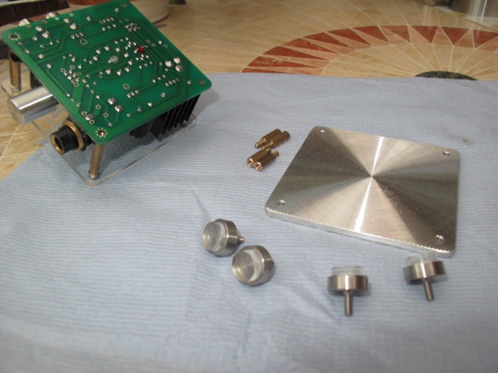 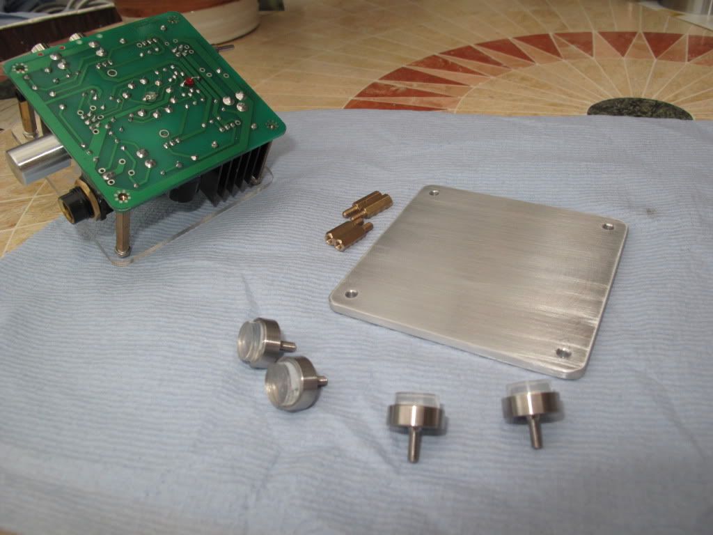 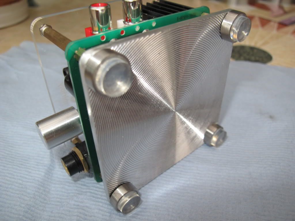 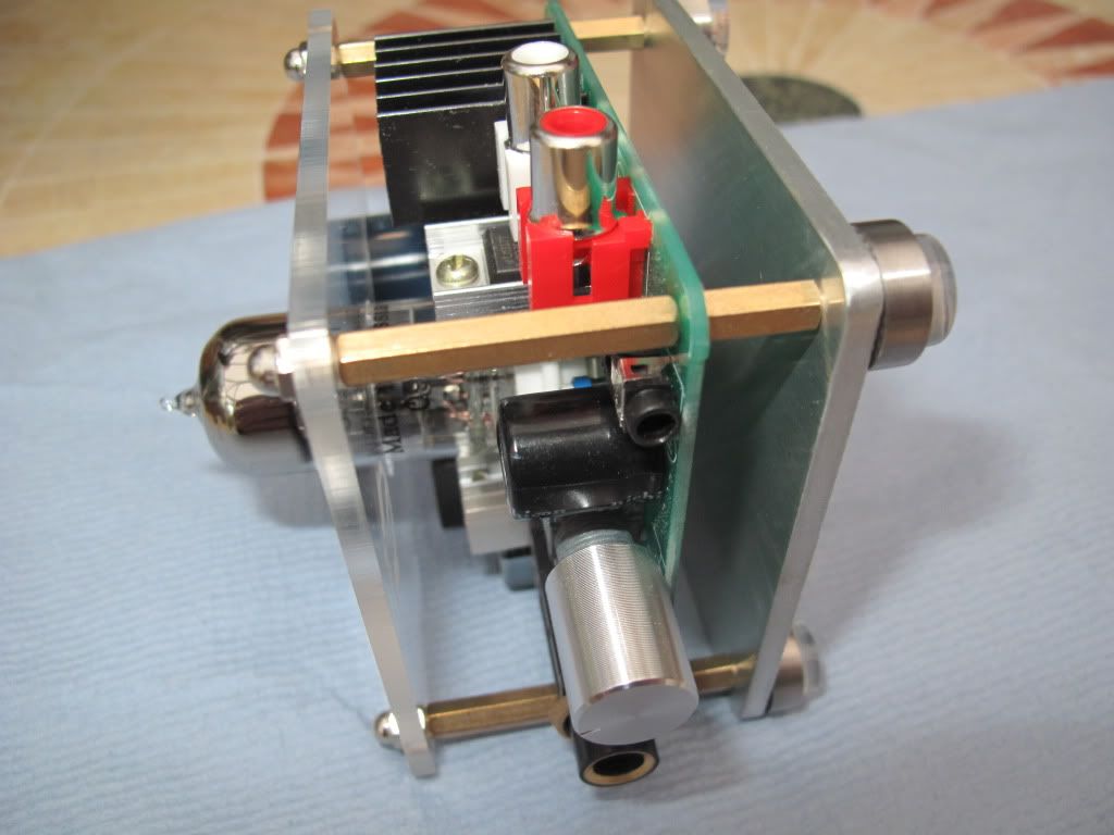 Dave, a photo of your TT Vinyl platter weights. 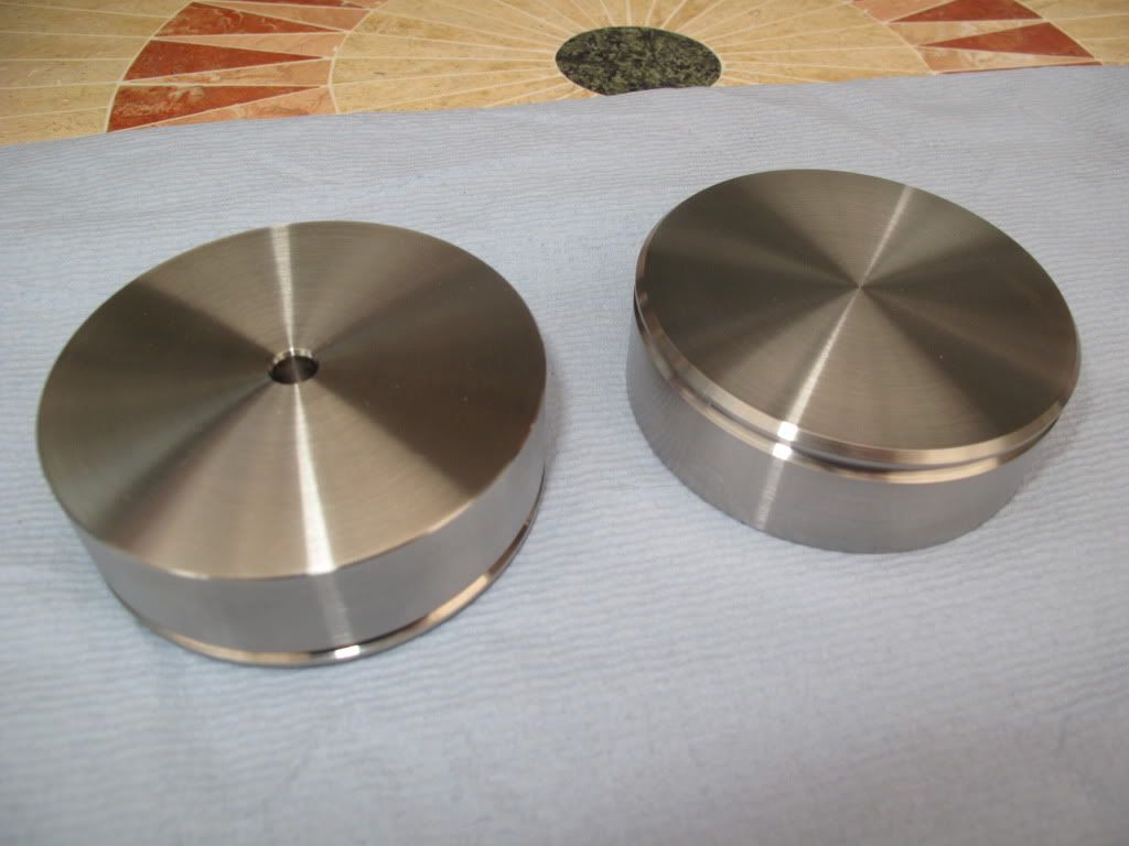 Mick. |
|
|
|
Post by PinkFloyd on May 9, 2010 11:25:00 GMT
Very nice Mick! I would also lose the perspex top cover and replace it with an aluminium one.... it would look good AND provide a bit of shielding.
Mike.
|
|
Deleted
Deleted Member
Posts: 0
|
Post by Deleted on May 9, 2010 11:53:05 GMT
Hi Mick, I just wanted to post publicly my great appreciation, and that of Jerry, for the brilliant TT Weight/Clamps. They look superb, neat, simple but functional design - I'm sure they will deliver the goods, sound wise. If you can get them to me before the end of the week I'll happily cover all costs before I leave the country  . Thanks again, Dave. |
|
|
|
Post by noobiiee on May 14, 2010 11:23:57 GMT
just got my Bravo today. It makes my K601 (which is notorious for its power thirst) siiinnggg!! Waiting for my mod kit to arrive  |
|
|
|
Post by mrB on May 16, 2010 19:51:08 GMT
Greetings Solderdude, I noticed you left out the blue LED in your redesigned amp. I actually would like to keep it in mine. Could I just leave it in series with the red LED and cut the track to the LM317 and solder a connection to ground, and swap the 1k5 for a 10k as in your new design? Would this give the correct bias for the CCS 2N3906's? I was going to leave them in unless you particularly feel I should replace them with the BC556B's. I am curious why you have reduced the size of the PS smoothing cap? Isn't bigger better? I have been using 8 x 2200uF in parallel for months now without blowing up the 2 amp switching supply that came with my Indeed. Cheers! For those that are interested in the changes I made in the schematics of the Bravo/Indeed/Miridiy/Sijosae amps.  (original)  (modded) You can use the original PCB but have to cut some traces and re-route some wiring, add and replace some parts.  The LM317's cannot remain on their current (very small) cooling fins anymore and have to be placed on a much larger cooling surface for this to work. Maybe a tutorial in the future.  |
|
|
|
Post by PinkFloyd on May 16, 2010 20:02:59 GMT
I have been using 8 x 2200uF in parallel for months now without blowing up the 2 amp switching supply that came with my Indeed. Wowee! where did you fit them? I'm using one x 10,000uF which "just" fits onto the board sideways..... have you got the 8 x 2200uF offboard? I see no problems with 17,600uF (8 x 2200) but am sure that all that is really required.... I thought 10,000uF may have been overkill  |
|
|
|
Post by mrB on May 16, 2010 20:26:39 GMT
I have been using 8 x 2200uF in parallel for months now without blowing up the 2 amp switching supply that came with my Indeed. Wowee! where did you fit them? I'm using one x 10,000uF which "just" fits onto the board sideways..... have you got the 8 x 2200uF offboard? I see no problems with 17,600uF (8 x 2200) but am sure that all that is really required.... I thought 10,000uF may have been overkill  Got them sitting on the ground floor, The amp's been up on stilts without the top plate since I got this idea (a rearrangement of the supplied plates and spacers). This leaves a lot of room downstairs for extra componentry. It's not elegant what I've done .... |
|
Deleted
Deleted Member
Posts: 0
|
Post by Deleted on May 16, 2010 21:10:40 GMT
You can leave the blue diode in place (Ian didn't like it so took it out, I find it ...um ... yes .... eh.. too so to speak)
You might want to change the 10k resistor back to a smaller one if you think the blue LED isn't bright enough anymore.
anything between 10k and 1k5 will do.
Bias is not changed with 10k or 1k5 as the voltage across the red LED is almost the same at these currents (acts like a zener diode).
I used BC556B because one of the original transistors became defective while experimenting.
Feel free to use the original transistors.
I have different views on caps as many others here have...
I know, doesn't make me a guru ...
The SMPS's won't break when using large caps.
The current is only high at start-up and all SMPS have current limiters so no probs there.
In linear power supplies the power fed into the caps is replanished every 10mS (100Hz)
In SMPS they are charged at a much higher rate (20 microseconds or so)
About 500 times as often.
You might destroy the fragile power switch on these amps.
They are really poor quality..
If you want to improve on attack... use the capacitors that are used in flash guns and put one of these in parallel to a normal cap.
Bigger caps have POOR HF properties.
Smaller caps have better HF properties.
Very simple due to less windings of the plates the inductance of smaller caps is measurably better.
Flash caps are SPECIALISED in delivering high pulses of current with huge power in a very short time.
They have a different construction.
I am amazed these caps haven't made it into audioland yet.
My power amps are equipped with these caps for over 20 years already..
|
|
|
|
Post by PinkFloyd on May 16, 2010 22:15:04 GMT
I am amazed these caps haven't made it into audioland yet. My power amps are equipped with these caps for over 20 years already.. Links to these caps Frans? |
|
|
|
Post by PinkFloyd on May 16, 2010 22:18:00 GMT
|
|
|
|
Post by PinkFloyd on May 16, 2010 22:25:07 GMT
|
|
|
|
Post by clausdk on May 16, 2010 23:16:34 GMT
That video was a bit dissapointing   |
|
Deleted
Deleted Member
Posts: 0
|
Post by Deleted on May 17, 2010 6:41:17 GMT
Yes Mike,
something like that.
When I worked at Panasonic I had easy access to these caps (National flashguns)
Nowadays when I need them I buy 2 (the same type) cheap but powerfull secondhand flashguns (GN 32 - GN45) and salvage the caps.
Try them in power amps Mike... see what it does with the attack !
Mount them as close as possible to the amp PCB with short rather thick wires (not necessarely close to the power caps if these are away from the PCB)
They are usually 400V types in the range of 100 - 470uF.
Use them in parallel to the normal powercaps (these deliver the bass punch)
When you short normal caps you hear a 'poff' to perahaps a 'paff' sound.
Wouldn't advise it as normal caps are not meant to be shorted, flash caps are built for it.
When you short a flash cap you'll hear a very sharp 'tack' so to speak.
the dV/dt (risetime) is MUCH faster and thus can deliver much power in a very short time which is needed for attack when feeding LS.
|
|
|
|
Post by mrB on May 17, 2010 8:49:47 GMT
You can leave the blue diode in place (Ian didn't like it so took it out, I find it ...um ... yes .... eh.. too so to speak) You might want to change the 10k resistor back to a smaller one if you think the blue LED isn't bright enough anymore. anything between 10k and 1k5 will do. Bias is not changed with 10k or 1k5 as the voltage across the red LED is almost the same at these currents (acts like a zener diode). I used BC556B because one of the original transistors became defective while experimenting. Feel free to use the original transistors. I have different views on caps as many others here have... I know, doesn't make me a guru ... The SMPS's won't break when using large caps. The current is only high at start-up and all SMPS have current limiters so no probs there. In linear power supplies the power fed into the caps is replanished every 10mS (100Hz) In SMPS they are charged at a much higher rate (20 microseconds or so) About 500 times as often. You might destroy the fragile power switch on these amps. They are really poor quality.. If you want to improve on attack... use the capacitors that are used in flash guns and put one of these in parallel to a normal cap. Bigger caps have POOR HF properties. Smaller caps have better HF properties. Very simple due to less windings of the plates the inductance of smaller caps is measurably better. Flash caps are SPECIALISED in delivering high pulses of current with huge power in a very short time. They have a different construction. I am amazed these caps haven't made it into audioland yet. My power amps are equipped with these caps for over 20 years already.. My power switch gave up after about a month anyway, just physically wore out the catch. A mains-type switch should hold up to these switch-on currents, I was thinking. Good info on caps. I noticed the original 2200uF cap in my amp is only rated 25V. What happens if it fails? Fireworks? and is there a risk of damage to the rest of the amp in any way? Would a battery-powered flash unit yield a usable capacitor for this amp. Perhaps they use voltage multipliers to get the voltage they need to operate, thus use caps rated over 30V? cheers Frans  |
|
Deleted
Deleted Member
Posts: 0
|
Post by Deleted on May 17, 2010 9:03:23 GMT
the 25V power cap is a bad thing.
That's why I replaced with a 35 V cap.
In order for it to physically fit I fitted 3300/35V which should be more then adequate.
If you feel the need to fit larger caps then you would have to fit them elsewhere (like Mike's rocket powered amp, or like you did on the bottom)
the battery operated flashguns all have high voltage caps between 350 and 450V (needed voltage to power the flashtube).
Small guns (GN11 to GN20 e.t.c.) have smaller caps (47uF/400V e.t.c.) but are likely to do their business here.
Each battery operated flashgun has an oscilator to make the high voltage (the beeping sound you hear)
HiVi makes really nice speakers !
rebel... kill the blue lights !
Me personally finds them to 'flashy' and most of the times far too bright !
In principle I like blue colored led's but make the amp look tacky IMO
I prefer to only see the tubes glowing, personal opinion though.
|
|
|
|
Post by mrB on May 21, 2010 20:05:44 GMT
Greetings Dude!
I've been looking at replacing the 100nF HF shunt capacitor on the 24V rail with a WIMA foil type, as was suggested in posts here and there. I went to the German Conrad website and found they have 3 different types and I have no idea which is the appropriate one. This is what they have: FKP-, FKS-, and MKS-Folienkondensatoren. All rectangular red plastic looking things. Can you help me make the right choice? Do you think 100nF is the optimum value for the job?
Hoping to come across a flashgun cap somewhere too.
|
|
Deleted
Deleted Member
Posts: 0
|
Post by Deleted on May 22, 2010 4:46:36 GMT
Greetings Dude! I've been looking at replacing the 100nF HF shunt capacitor on the 24V rail with a WIMA foil type, as was suggested in posts here and there. I went to the German Conrad website and found they have 3 different types and I have no idea which is the appropriate one. This is what they have: FKP-, FKS-, and MKS-Folienkondensatoren. All rectangular red plastic looking things. Can you help me make the right choice? Do you think 100nF is the optimum value for the job? Hoping to come across a flashgun cap somewhere too. mrb Unless I am mistaken, there are already 2 x 100nF in parallel with the electrolytic capacitor. Personally, I think what you propose would be a waste of time and money. Regarding the 100uF flash capacitors, I think their use is also likely to be a waste of time in anything but a solid state amplifier with considerably higher output capabilities than a typical headphone amplifier. Their main advantage is their instantaneous power delivery compared to typical electrolytics. Nevertheless, some of the expensive larger capacitance boutique electrolytics also have far better than average short term capabilities due to their very low E.S.R. (Effective Series Resistance), and a smaller parallel 100uF capacitor with such characteristics would most likely be a waste of time when they are used. SandyK |
|
Deleted
Deleted Member
Posts: 0
|
Post by Deleted on May 22, 2010 6:03:27 GMT
Sandy K is RIGHT on the money !!!  I use the flashcaps in power amps next to some large (old) powercaps that have bad HF properties. In HP'amps (especially class A) it seems a waste of time and money to fit flashcaps. There is no 'fast power' needed. Stranger things have happened in audioland and you are welcome to try of coarse and share your findings.  I don't do it when modding Bravo (and alike) amps in any case. I don't feel the need.  Ceramic caps usually have better RF properties then foil type caps. There is NO chance of oscilations in the Bravo so they are not necesary for this purpose. Only to filter some leftover garbage from the SMPS... Foil types do an evenly good job at that then ceramic caps as the freq. of the harmonics doesn't go that far up. I recommend a linear (regulated) PS for these amps as the amp is VERY susceptibel for any variations on the Power supply (a very low PS suppression ratio) The transformer in it will get warm/hot because there is a constant current. use at least a 1.5A power supply. |
|
|
|
Post by mrB on May 22, 2010 13:33:57 GMT
Thanks Sandy and Solderdude.  The intention with the foil cap was to clean up any HF from the SMPS ... I don't have a black backdrop at the moment, but not too disturbing. I can go linear PS later if things aren't satisfactory after the rebuild. Note to Sandy: my Indeed version 1 doesn't have those two 100nF caps that appear on Solderdude's drawing. Mine has a single small blue plastic chip cap just behind the DC input socket. Don't know the value. Ceramic caps usually have better RF properties then foil type caps. There is NO chance of oscilations in the Bravo so they are not necesary for this purpose. Only to filter some leftover garbage from the SMPS... Foil types do an evenly good job at that then ceramic caps as the freq. of the harmonics doesn't go that far up. I recommend a linear (regulated) PS for these amps as the amp is VERY susceptibel for any variations on the Power supply (a very low PS suppression ratio) The transformer in it will get warm/hot because there is a constant current. use at least a 1.5A power supply. |
|