|
|
Post by PinkFloyd on Mar 24, 2009 11:37:58 GMT
Yep Nick.... top marks, that's one superb looking piece of craftsmanship.... totally awesome  |
|
Deleted
Deleted Member
Posts: 0
|
Post by Deleted on Mar 24, 2009 17:57:46 GMT
All of the above x2. Additonaly what I like most is that, to me at least, the case work says traditional valve amp BUT there's solid state inside.
Maybe a wooden volume knob? Rolls Royce, PAH!, we got nickyboyo!
|
|
|
|
Post by nickyboyo on Mar 25, 2009 9:30:35 GMT
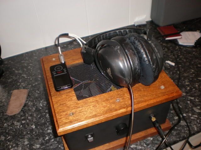
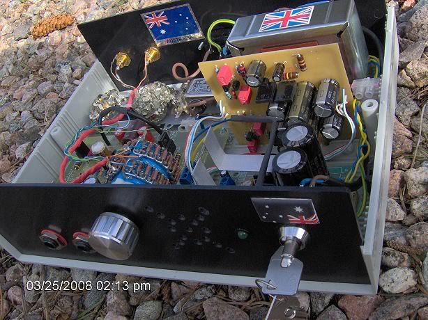
Thank you very much for the comments folks. Yes, i am rather pleased how it turned out, aesthetically and performance wise, it is one mean piece of kit. If it wasn't for reading your posts and your enthusiasm about this amp, i wouldn't of put the handy work into the case, but i knew from what i was reading it would be worth the effort- and i wasn't wrong  Now all i've got to do is find some better cans to do it justice, and keep up with the mods- keep them simple now please. |
|
Deleted
Deleted Member
Posts: 0
|
Post by Deleted on Mar 25, 2009 9:51:27 GMT
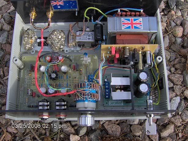
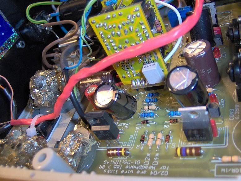
Thank you very much for the comments folks. Yes, i am rather pleased how it turned out, aesthetically and performance wise, it is one mean piece of kit. If it wasn't for reading your posts and your enthusiasm about this amp, i wouldn't of put the handy work into the case, but i knew from what i was reading it would be worth the effort- and i wasn't wrong Now all i've got to do is find some better cans to do it justice, and keep up with the mods- keep them simple now please. O.K. Nick, Just for you. As discussed, replace the 4 x 1N4004 diodes near the 3 terminal block where the secondary winding of the transformer is connected, with 4 x UF4003 (1A 200V Ultrafast diodes) available from Jaycar as cat. no. ZR1034 for 95C each.This complements the small 470 picofarad capacitor which is connected across the 2 outer terminals of the 3 terminal AC input. This combo of mods is often likened to lifting a fine veil. Check that the output of your source has no more than a few millivolts DC at the RCA plugs when not playing music, but switched on. If all O.K. , put a big blob of solder across both input capacitors, where you have them soldered into the PCB. Simple enough? Alex |
|
|
|
Post by nickyboyo on Mar 25, 2009 10:38:24 GMT
Do you mean ZR1034's Alex? I will buy some on Saturday in Penrtih hopefully, just making sure i have the right number.
|
|
Deleted
Deleted Member
Posts: 0
|
Post by Deleted on Mar 25, 2009 10:45:12 GMT
nick Sorry. Yes, I meant ZR1034. You may not notice much difference until you upgrade your headphones though. Perhaps you can strike a deal. Furniture shopping only if headphone shopping too ?  Alex |
|
Will
Been here a while!  Ribena abuser!
Member since 2008
Ribena abuser!
Member since 2008
Posts: 2,164
|
Post by Will on Mar 25, 2009 11:16:53 GMT
Nick, Embezzle the joint account for a while, then see what headphones you 'win'. It amazing the luck I've had in the past ;D |
|
|
|
Post by PinkFloyd on Mar 25, 2009 16:21:03 GMT
|
|
|
|
Post by nickyboyo on Mar 25, 2009 19:32:50 GMT
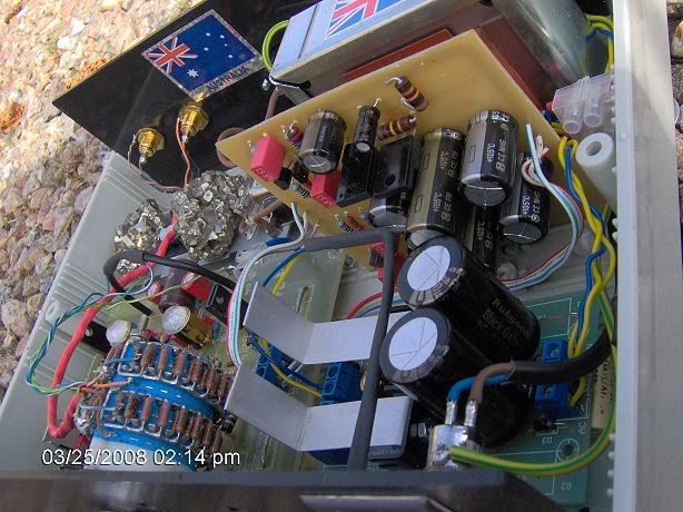
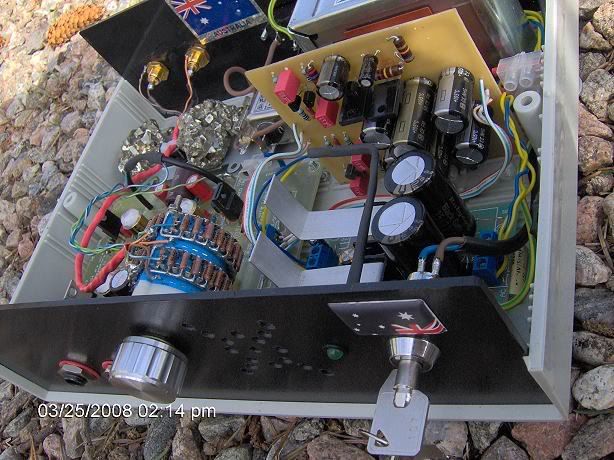
Mate, that amp should carry an X rating, it is pure diy tinkerer's porn, i'm getting strange twitchings just imagining what the lumps of fool's gold actually do.
There is no way on this Earth would the mrs let me put it in a room which i watched her personally decorate for 2 weeks, note the use of "watched", decorating's a womans job in my house. Personally, i love it.
I'd make myself another amp like yours, if only i knew what the f... the different components did to the sound output of the amp and i had the ability to have a good guess as to how the component changes would effect the noise pumped out at the listening end. It's a modifiers dream.
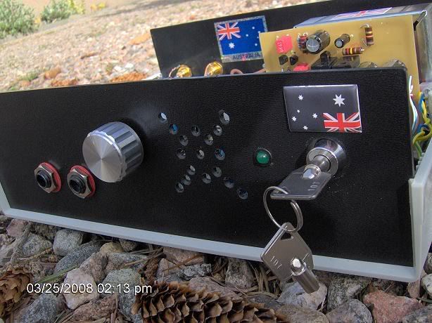
Favourite touches- Lumps of iron, upside down Aussie sticker (great touch), ginormous volume control, ignition keys (love that idea) and capacitors in cases big enough to double as grain silos. Oh yeah, accessibility is a huge plus to.
|
|
|
|
Post by jphoward on Mar 26, 2009 4:05:06 GMT
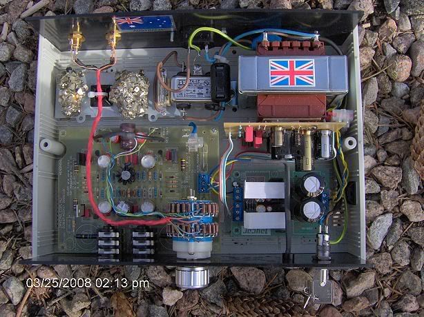
Purely for interest's sake, here's mine. Be nice! - it's my 1st ever electronics project. I majored in philosophy at uni, and as you can see it didn't help me build attractive cases!  Anyhoo, it's basically as per Alex's tweaks, including removing the input caps, but as yet without a ripple eater. 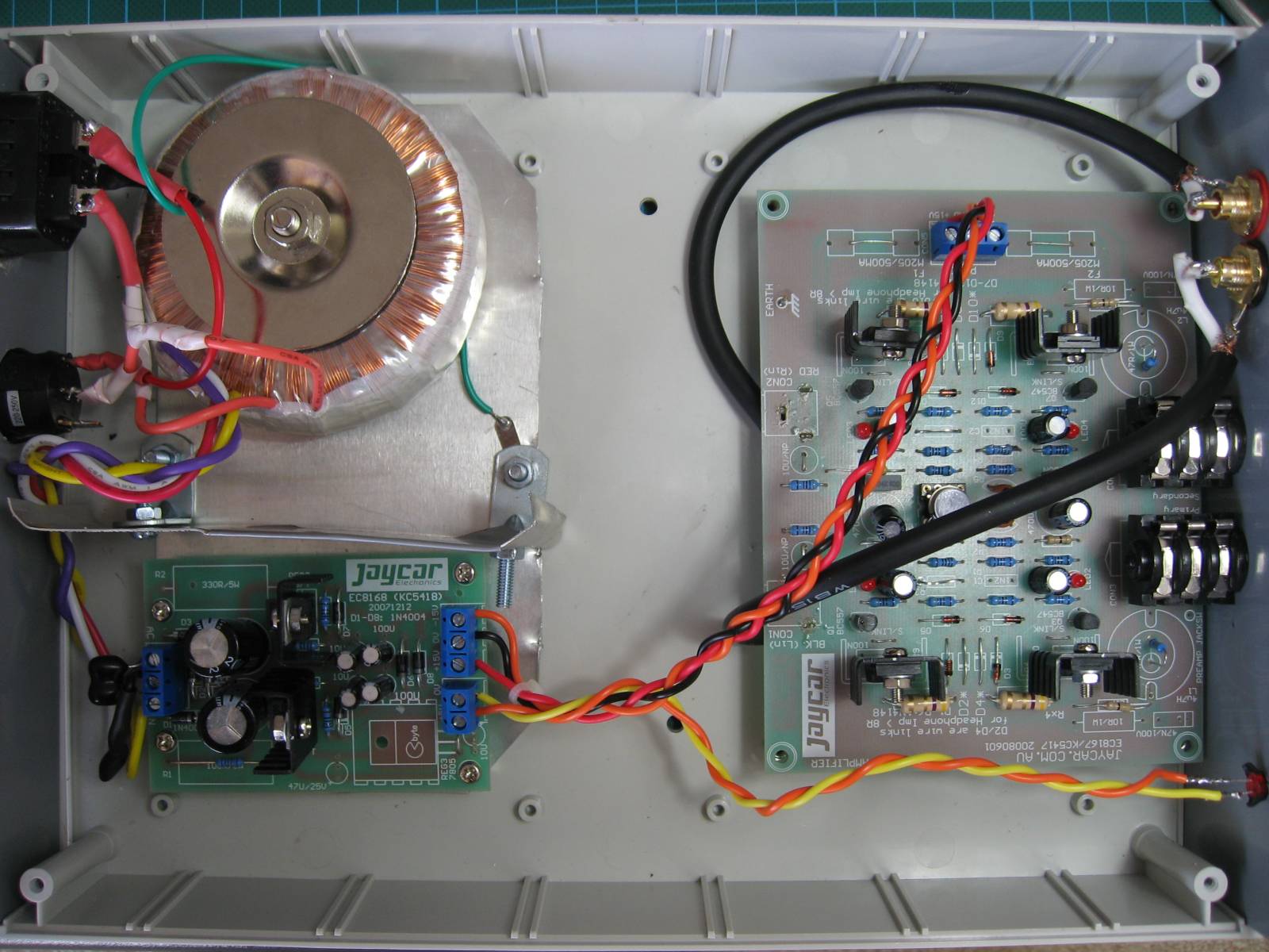 Any advice on how to go about things next time around will be much appreciated! |
|
Deleted
Deleted Member
Posts: 0
|
Post by Deleted on Mar 26, 2009 4:22:25 GMT
Jeremy A couple of minor suggestions. Try slipping some heatshrink tubing over all the exposed mains connections. You may be very glad that you did, some day. Inadvertently just touching 230/240VAC can throw you across a room,and render you speechless for a while. (or forever ,if you have a weak ticker  ) Also, if possible, try to use more contrasting colours for DC wiring. Orange and red are a little too similar.Red,orange,and brown are the best choices for positive.Black, blue,or white are the best choices for negative. Colours like green,or green/yellow are good choices for earth/0 Volts. Other people will of course have different, but no less valid suggestions. Recovered mains cables from defunct electric jugs etc. are a good source of suitable wire. A few people recently appear to have caused damage by inadvertently reversing DC supply wiring during modifications. Alex |
|
Spirit
Been here a while!
That's where I'm gonna go when I die
Posts: 1,107
|
Post by Spirit on Mar 26, 2009 6:18:35 GMT
I love the keyed ignition Mike  |
|
|
|
Post by nickyboyo on Mar 26, 2009 7:17:03 GMT
Folks, if any of you require aluminium ground plates, steel shielding angles or any other sheetmetal items for your amps please feel free to drop me a message and i see what i can do. Being a sheet metal worker by trade has it's advantages Just let me know your ideas and i'll see what we can do. |
|
Will
Been here a while!
Ribena abuser!
Member since 2008
Posts: 2,164
|
Post by Will on Mar 26, 2009 8:53:35 GMT
Hi Jeremy,
that is a damn fine first effort, especially, as you mentioned, electronics is out of trade!
It looks like you are using the LM4562HA opamp? If you are, I would really recommend your next step is to ask Uncle Spirit (I'm assuming you are an Aussie) if he could make you a JLH. It'll really lift an already great amp to another level.
Also, what form of volume control are you using?
|
|
Spirit
Been here a while!
That's where I'm gonna go when I die
Posts: 1,107
|
Post by Spirit on Mar 26, 2009 9:37:12 GMT
Will, Jeremy is indeed an Aussie, and his JLH will be arriving tomorrow |
|
|
|
Post by jphoward on Mar 26, 2009 20:04:00 GMT
Try slipping some heatshrink tubing over all the exposed mains connections Actually, I tried to do that - you can see the blue tubing where the IEC socket is connected. However, as you can also see, it slipped off the actual metal connector. When I applied heat to the tubing, it shrunk away from the connector leaving it exposed. I also tried electrical tape, but it didn't stick very reliably. Any suggestions? That would be me. |
|
|
|
Post by jphoward on Mar 26, 2009 20:06:29 GMT
that is a damn fine first effort, especially, as you mentioned, electronics is out of trade! You are too kind. My wife is an artist, and I think I may have convinced her to help me design the front panel, so with a bit of luck the outside might look good enough to match with the nice sound from the inside. My source has a volume control. |
|
Deleted
Deleted Member
Posts: 0
|
Post by Deleted on Mar 26, 2009 20:15:41 GMT
Jeremy
Tricky stuff, isn't it ? I try to start off with pieces about half as long again as needed,but not too loose a fit, then slide them way back on the wire so that the heat of the soldering iron doesn't prematurely shrink them.Unless you have a special low powered heat shrink gun, it could be worthwhile slowly shrinking the tubing with the heat of your soldering iron, it's fiddly to do, and slow ,and as long as you have steady hands and are very careful not to burn something else, will do the job.BTW, The gun that Nick used was VERY suitable for the purpose, much more so than my DSE heatshrink gun.
Alex
|
|
|
|
Post by PinkFloyd on Mar 26, 2009 20:36:16 GMT
|
|
|
|
Post by PinkFloyd on Mar 26, 2009 20:47:17 GMT
All this to be housed in a very nice enclosure once I am "finally" sure what's staying and what's going!.... the cheap plastic enclosure has served a purpose and has allowed me to whack in different parts without worrying about scratching an Uber cool enclosure..... don't worry Alex, all mains connections etc. will be suitably wrapped in the final version |
|
|
|
Post by jphoward on Mar 29, 2009 9:19:51 GMT
Well the JLH PSRR is in now - had to move the PSU and shield, but I managed to squeeze it in. The PSRR is well worth the effort...  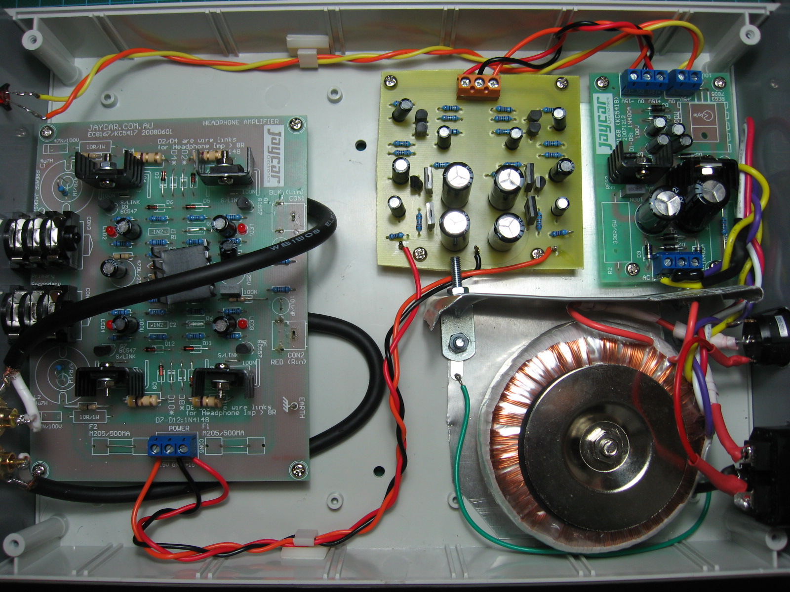 |
|
|
|
Post by nickyboyo on Mar 29, 2009 10:07:10 GMT
jp, that is fantastic work for your first build mate. Serious cahoonas for wiring up the 240v side of things. I needed a lesson in electrical common sense before i wired mine in. Nice and tidy wiring on the inside. If you would like a new base plate and shielding angle just to tidy up the transformer section just let me know. Great work |
|
|
|
Post by jphoward on Mar 29, 2009 10:17:40 GMT
That's very nice of you to say so - I do wish I had your skills in presentation! For the transformer side of things I read Alex's notes on wiring it up, and also did plenty of reading on the 'net. The way I figure it, if ya don't touch the wires, ya can't get a shock!  |
|
Spirit
Been here a while!
That's where I'm gonna go when I die
Posts: 1,107
|
Post by Spirit on Mar 29, 2009 10:55:41 GMT
I hope the other JLH was a little better presented than that one... ;D Didn't do quite as good a job on the corners as I'd thought... (was filing them down at 3:45.... post office closed at 4  ) |
|
|
|
Post by jphoward on Mar 29, 2009 12:50:38 GMT
I hope the other JLH was a little better presented than that one... Oh sorry Spirit - that's my fault!  I took to them with shears to make it smaller. I have so little pride in my workmanship that I didn't bother to file it at all! |
|


 Now all i've got to do is find some better cans to do it justice, and keep up with the mods- keep them simple now please.


 Anyhoo, it's basically as per Alex's tweaks, including removing the input caps, but as yet without a ripple eater.
 )
)


 )
) I took to them with shears to make it smaller. I have so little pride in my workmanship that I didn't bother to file it at all!