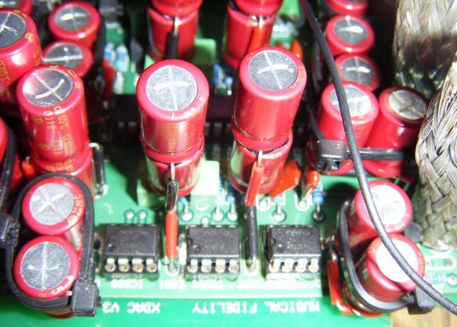
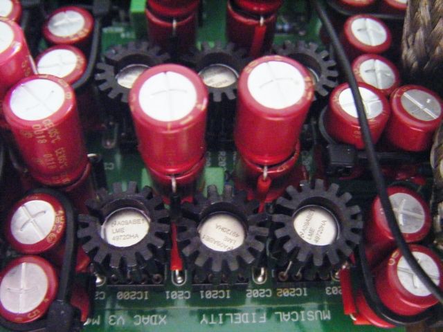
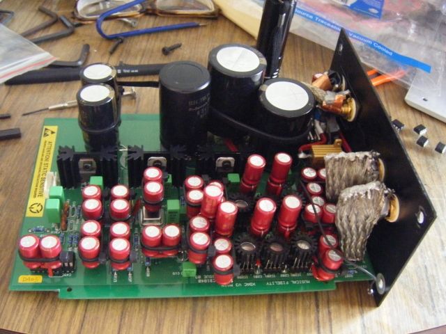
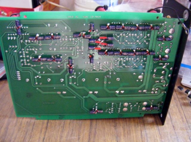
From Shitty X-DAC V3 To Something
May 16, 2008 10:46:08 GMT
Post by XTRProf on May 16, 2008 10:46:08 GMT
FACT 13: Is 12,000 uf really superior to lower value e-caps at PS? Here is the fact,
Filtering crossover or cutoff frequency f = 1 / 2 pi R C
Z (impedance) = square root ( R square + C square)
where Xc = 1 / 2 pi f C
My case, R = 2.5 ohms and C = 12,000 uf
So f = 1 / (2 x 3.142 x 2.5 x 0.012)
= 5.3045 Hz for 4 decimal places
At say, 100 Hz, Xc = 1 / (2 x 3.142 x 100 x 0.012)
= 0.1326 ohms to 4 decimal places
Z = square root ( 2.5 square + 0.1326 square)
= 2.5035 ohms to 4 decimal places
So basically with the Xc in it, the PS network still acts like a resistor of 2.5 ohms, the original resistor at 100 Hz.
For C = 100 uf (I'm not poking at anyone but just using this as a comparative figure to work out something),
f = 1 / (2 x 3.142 x 2.5 x 0.0001)
= 636.5372 Hz for 4 decimal places
At say, 100 Hz, Xc = 1 / (2 x 3.142 x 100 x 0.0001)
= 15.9134 ohms to 4 decimal places
Z = square root ( 2.5 square + 15.9134 square)
= 16.1086 ohms to 4 decimal places
So basically with the Xc in it, the PS network will give a higher resistance at using a 100 uf e-cap although small.
This means the filtering starts at - 3 db at those frequencies when filtering the incoming PS. All these are assuming no inductance influences.
FACT 14: Inductance importance in PS Here, goes:
XL = 2 pi f L
As I have no LCR meter, let us assume and work out some figures. As there is basically no winding in the copper trace, we can start off by assuming similar to any IC inductance at
Inductance (L) = 0.82uH/foot run
Reference: Here!
As the PS copper trace is estimated at about 6 inches (conservatively),
L = 0.82 / 2
= 0.41 uH
XL = (2 x 3.142 x 100 x 0.41 ^ -6)
= 0.000257644 ohms
So as good as forget about it! Not until we go inside the OPAs for parasitic capacitance and inductance effects. In fact, I was hoping for higher XL as that will give at least some more load and line voltage control like a Vreg. Hmm, maybe I add an inductor here for better ripple control. No, no, KISS for best sound, unless I get 2.5 ohms, as that's not so important for analog audio amps. Unlike digital cases at low voltages.
FACT 14: For oscillation and peaking of OPA control from usually capacitance, check up the application notes of OPAs like 8066 and 4562. I'm not going to rewrite something that's known to many already as I respect you as knowledgeable individuals. It just boils down to feedback resistor, feedback caps, PS stabilisation near to the OPAs and isolation from the output.
That's all folks for now as I need some relaxation after struggling through these after many years of not doing these since student days. I had relearned many things by going thru this paperweight mortar board excercise.
Filtering crossover or cutoff frequency f = 1 / 2 pi R C
Z (impedance) = square root ( R square + C square)
where Xc = 1 / 2 pi f C
My case, R = 2.5 ohms and C = 12,000 uf
So f = 1 / (2 x 3.142 x 2.5 x 0.012)
= 5.3045 Hz for 4 decimal places
At say, 100 Hz, Xc = 1 / (2 x 3.142 x 100 x 0.012)
= 0.1326 ohms to 4 decimal places
Z = square root ( 2.5 square + 0.1326 square)
= 2.5035 ohms to 4 decimal places
So basically with the Xc in it, the PS network still acts like a resistor of 2.5 ohms, the original resistor at 100 Hz.
For C = 100 uf (I'm not poking at anyone but just using this as a comparative figure to work out something),
f = 1 / (2 x 3.142 x 2.5 x 0.0001)
= 636.5372 Hz for 4 decimal places
At say, 100 Hz, Xc = 1 / (2 x 3.142 x 100 x 0.0001)
= 15.9134 ohms to 4 decimal places
Z = square root ( 2.5 square + 15.9134 square)
= 16.1086 ohms to 4 decimal places
So basically with the Xc in it, the PS network will give a higher resistance at using a 100 uf e-cap although small.
This means the filtering starts at - 3 db at those frequencies when filtering the incoming PS. All these are assuming no inductance influences.
FACT 14: Inductance importance in PS
 Here, goes:
XL = 2 pi f L
As I have no LCR meter, let us assume and work out some figures. As there is basically no winding in the copper trace, we can start off by assuming similar to any IC inductance at
Inductance (L) = 0.82uH/foot run
Reference: Here!
As the PS copper trace is estimated at about 6 inches (conservatively),
L = 0.82 / 2
= 0.41 uH
XL = (2 x 3.142 x 100 x 0.41 ^ -6)
= 0.000257644 ohms
So as good as forget about it! Not until we go inside the OPAs for parasitic capacitance and inductance effects. In fact, I was hoping for higher XL as that will give at least some more load and line voltage control like a Vreg. Hmm, maybe I add an inductor here for better ripple control. No, no, KISS for best sound, unless I get 2.5 ohms, as that's not so important for analog audio amps. Unlike digital cases at low voltages.
FACT 14: For oscillation and peaking of OPA control from usually capacitance, check up the application notes of OPAs like 8066 and 4562. I'm not going to rewrite something that's known to many already as I respect you as knowledgeable individuals. It just boils down to feedback resistor, feedback caps, PS stabilisation near to the OPAs and isolation from the output.
That's all folks for now as I need some relaxation after struggling through these after many years of not doing these since student days. I had relearned many things by going thru this paperweight mortar board excercise.


