leo
Been here a while!  Team wtf is it?
Posts: 3,638
|
Post by leo on Apr 15, 2008 8:17:44 GMT
Draw a quick rough circuit showing how things are currently running, it makes it easier for us to advise what to try especially us who don't have an X-dac V3
|
|
leo
Been here a while!  Team wtf is it?
Posts: 3,638
|
Post by leo on Apr 15, 2008 8:26:02 GMT
Its surely easy enough to tap in a couple of the small packaged fixed regulators in there? improve the PSRR for the op-amp will bring audible improvements
|
|
Deleted
Deleted Member
Posts: 0
|
Post by Deleted on Apr 15, 2008 14:54:06 GMT
For those, like myself, who have very limited knowledge (just enough to be dangerous!) please take heed.
I'm reminded of an experience myself and a colleague had with a MF P270, we thought our changes were a great idea until switch-on.
Voooooooosh, crackle, sparks and you wouldn't believe the smoke!
In the 15 seconds or so it took me hit the trip for the mains supply the innards were toast. A VERY costly repair followed.
I vowed to stay within my, or very well sourced, knowledge ever since.
|
|
XTRProf
Fully Modded
Pssst ! Got any spare capacitors ?
Posts: 5,689
|
Post by XTRProf on Apr 16, 2008 7:20:55 GMT
XTRProf Haven't you heard of devices that are designed to work with single rail voltages ? I dare you to plug an AD8066 into your X-DAC V3 with your present voltage !Seeing you are so gung ho, and disbelieving, cast your eyes over the section from another couple of excellent audio device's specs. You will probably brush aside their warnings too ? This does NOT mean + and -27.3V either!or in the case of the AD8066, working with an effective overall voltage of 52.8V !!! Still not convinced? "IC Module AD8066 - Soundlabs Group For this reason we can supply it on an adapter PCB to make this easy! ... Note: The AD8066 has a maximum voltage rating of ±13V, so please ensure your ... www.soundlabsgroup.com.au/p/IC-Module-AD8066/IC+Module+AD8066 - 12k - Cached - Similar pages - Note this " Alex AD8065/AD8066 Rev. E | Page 6 of 28 ABSOLUTE MAXIMUM RATINGS Table 4. Parameter Rating Supply Voltage 26.4 V Power Dissipation See Figure 3 Common-Mode Input Voltage VEE − 0.5 V to VCC + 0.5 V Differential Input Voltage 1.8 V Storage Temperature −65°C to +125°C Operating Temperature Range −40°C to +85°C Lead Temperature Range (Soldering, 10 sec) 300°C Stresses above those listed under Absolute Maximum Ratings may cause permanent damage to the device. This is a stress rating only; functional operation of the device at these or any other conditions above those indicated in the operational section of this specification is not implied. Exposure to absolute maximum rating conditions for extended periods may affect device reliability. ESD CAUTION AD8610/AD8620 ABSOLUTE MAXIMUM RATINGS Table 3. Parameter Supply Voltage 27.3 V Input Voltage VS− to VS+ Differential Input Voltage ± Supply Voltage Output Short-Circuit Duration to GND Indefinite Storage Temperature Range R, RM Packages –65°C to +150°C Operating Temperature Range AD8610/AD8620 –40°C to +125°C Junction Temperature Range R, RM Packages –65°C to +150°C Lead Temperature Range (Soldering, 10 sec) 300°C Rating Stresses above those listed under Absolute Maximum Ratings may cause permanent damage to the device. This is a stress rating only; functional operation of the device at these or any other conditions above those indicated in the operational section of this specification is not implied. Exposure to absolute maximum rating conditions for extended periods may affect device reliability.
Table 4. Thermal Resistance Package Type èJA1 èJC Unit 8-Lead MSOP (RM) 190 44 °C/W 8-Lead SOIC (R) 158 43 °C/W 1 èJA is specified for worst-case conditions; that is, èJA is specified for a device soldered in circuit board for surface-mount packages. ESD CAUTION Rev. E Thanks Alex, I'm not disbelieving but just wanted to confirm as stated earlier. There are many things written that are ambigious and if we follow just like that we will get into trouble. I'm confirming as all specs are written as +/- stds as in BB, Linear, TI and even NJM. So now with Leo confirmation, that's right and AD is to blame from going from the norm. As I had prior said, I'm no terrorist and if not sure I will leave it until enough info had been gathered. I'm restating that here again.   So all reading here, please make sure you know what you are doing before switching on that button. Whether you are a terrorist or a genuine modder will depend on that. So all reading here, please make sure you know what you are doing before switching on that button. Whether you are a terrorist or a genuine modder will depend on that. |
|
XTRProf
Fully Modded
Pssst ! Got any spare capacitors ?
Posts: 5,689
|
Post by XTRProf on Apr 16, 2008 7:24:51 GMT
XTRProf, you should listen to the guy above, I can assure your going to run into problems my friend if your not careful! A lot of the newer opamps are now designed to run on lower supplys, running them to over their max rated spec not only reduces reliability but they also go noisy after long term use Running something like a AD8066 at +/-27v will instantly fry it ABSOLUTE MAXIMUM RATINGS Table 3. Parameter Supply Voltage 27.3 V Input Voltage VS− to VS+ That does not mean to run both its supply pins at both +27.3v to ground and -27.3v to ground , you pick +27.3v to ground or +13v AND -13v to ground Thanks Leo. That's what I'm asking and now it's confirmed. So all using AD8066, please heed this and don't be a terrorist!   |
|
XTRProf
Fully Modded
Pssst ! Got any spare capacitors ?
Posts: 5,689
|
Post by XTRProf on Apr 16, 2008 7:28:30 GMT
Draw a quick rough circuit showing how things are currently running, it makes it easier for us to advise what to try especially us who don't have an X-dac V3 I will love to but I don't have the circuit and the circuit drawing software as well but depending on copper lead trace.  |
|
XTRProf
Fully Modded
Pssst ! Got any spare capacitors ?
Posts: 5,689
|
Post by XTRProf on Apr 16, 2008 7:32:03 GMT
For those, like myself, who have very limited knowledge (just enough to be dangerous!) please take heed. I'm reminded of an experience myself and a colleague had with a MF P270, we thought our changes were a great idea until switch-on. Voooooooosh, crackle, sparks and you wouldn't believe the smoke! In the 15 seconds or so it took me hit the trip for the mains supply the innards were toast. A VERY costly repair followed. I vowed to stay within my, or very well sourced, knowledge ever since. Yup, you are very right. So don't be a "terrorist" unless you know what you are doing. But once you know the innards, it's actually quite simple. From my record so far, I had not blown up anything except for the fuse on purpose. You can ask Alex or Leo for that. |
|
XTRProf
Fully Modded
Pssst ! Got any spare capacitors ?
Posts: 5,689
|
Post by XTRProf on Apr 16, 2008 7:38:30 GMT
REPORTING PART TWONow for some pictures after burning the midnight oil yesternight. I only have enough oil for doing a proper DOUBLE screen (original flimsy copper tape + current tinned copper braid) screen of the audio wires after I had found some screen tinned copper braid, for I think 200A, at a broadcast wiring firm after I had searched around for sometime on this until yesterday and bingo I have it now. Success at last!  Sorry for the blur images as these were taken with a HP cam without macro feature. Before the tinned copper braid screen and just a flimsy copper tape screen 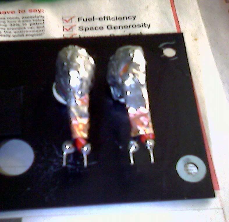 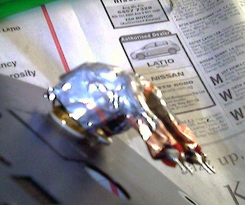 Now with the tinned copper braid in place 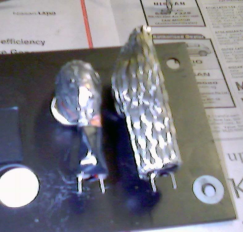 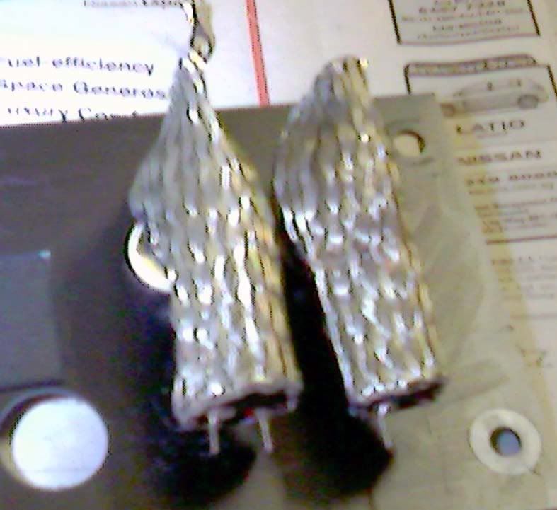 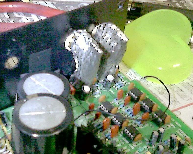 After this episode, the last few pictures reminded me of those knights and warriors in full ancient battle order armour. Sorry, what were those armour call?  I will try to get some thin copper plate to do Faraday cages for the analogue and digital sections, as promised much earlier, and also until I had found them at a reasonable price. SQ: Now the sound becomes super quiet and analog like with shitty sound as I have not installed the correct resistors yet to experiment the true Zen way.  So stick around and don't try if you are not sure. Repend as a "terrorist" and come out clean.   That's all folks for now. 
|
|
XTRProf
Fully Modded
Pssst ! Got any spare capacitors ?
Posts: 5,689
|
Post by XTRProf on Apr 18, 2008 9:31:50 GMT
|
|
Deleted
Deleted Member
Posts: 0
|
Post by Deleted on Apr 18, 2008 21:09:43 GMT
You could have done just as well, without making it very hard to pull the unit apart again, by using lengths of good quality double screened audio cable ! ;D
|
|
leo
Been here a while!  Team wtf is it?
Posts: 3,638
|
Post by leo on Apr 18, 2008 22:15:40 GMT
You could have done just as well, without making it very hard to pull the unit apart again, by using lengths of good quality double screened audio cable ! ;D It keeps him happy  |
|
Sol
100+
loves motorcycles !
Chief Technical Numpty
Posts: 135
|
Post by Sol on Apr 18, 2008 22:23:13 GMT
It keeps him happy  Of course it does .. it's half the fun  Maybe we should put a suffix to his name "Chief Electronic's Butcher" ... or ... "The Butcher of the East" ... eitehr way I've really enjoyed this thread.... and XProf ... go for it. What's the worst that can happen ;o) |
|
Deleted
Deleted Member
Posts: 0
|
Post by Deleted on Apr 18, 2008 23:42:01 GMT
|
|
XTRProf
Fully Modded
Pssst ! Got any spare capacitors ?
Posts: 5,689
|
Post by XTRProf on Apr 19, 2008 4:41:13 GMT
You could have done just as well, without making it very hard to pull the unit apart again, by using lengths of good quality double screened audio cable ! ;D Ha, ha, gurus .......... Yes, I understand. But unfortunately you have not seen the light of things. For a length of 1 m OCC copper with shield, only the branded names will carry them and you know how much a metre loose? Some obscene price of, say, at least SGD 50 a metre and that's most probably single shield and single run of internal signal wires. Now I had only spend SGD 12.60 for 2 metres (1 metre red teflon and 1 metre black teflon type of 20 gauge wire), with spare of 0.5m left per colour, of the OCC Diy loose ones and another probably SGD 2 for the thin copper tape and another SGD 13 for the 1 metre 200 A tinned copper braid. For the latter, I have only use about 0.1m of it with spare for other things like my Sansui tuner. Also, which branded cable has a double shield as thick as mine with an internal TRIPLE RUN of the red and black OCC wires each? With that thickness, even the hum will be much reduced as we know high frequencies interference will be stopped by a thin shield whereas low frequencies hum will need an obscenely thick shield (most probably at least 10mm and above as I have not found the formula to calculate that). That will depend on the wavelengths of the frequencies we are talking about. So I have only spend a total of SGD (12.60 + 2 + 13) = SGD 27.60 for that kind of "cost-no-object" screening. So which is better? I might look "mad" but I go for the absolute MAXIMUM VALUE when doing things since I'm already into it. If don't do a good job, I might as well fire myself. Anyway, I will try to source for some copper plates to work on for screening the audio and digital sections after some rough design drafts. So keep yourself posted on this. Heh, heh and back to work after almost burning all the midnight oil. I have only about 3 hours of shut eyes before I log into Rockgrotto now. Ya, my family thinks I'm a lunatic without sanely cause. Well, that's their opinions and not mine!  MAY THE BEST SOUND WINS! MAY THE BEST SOUND WINS!Aiyah, not good enough and so .................   MAY THE BEST SOUND BE WITH YOU! MAY THE BEST SOUND BE WITH YOU!   |
|
XTRProf
Fully Modded
Pssst ! Got any spare capacitors ?
Posts: 5,689
|
Post by XTRProf on Apr 19, 2008 5:05:45 GMT
It keeps him happy  .... and XProf ... go for it. What's the worst that can happen ;o) Err....................., I can still be a "terrorist", you know, when I haven't understand enough before switching on. Ka boom .................. and smoke everywhere.................. Ok, ok, not those nice smoke as in disco, ok? My family will then call up the Singapore internal security (similar to FBI or CIA) to arrest me and put me into the asylum, man!  |
|
XTRProf
Fully Modded
Pssst ! Got any spare capacitors ?
Posts: 5,689
|
Post by XTRProf on Apr 19, 2008 5:11:31 GMT
You could have done just as well, without making it very hard to pull the unit apart again, by using lengths of good quality double screened audio cable ! ;D It keeps him happy  More happy than sleeping, man! Ok, jokes aside, Leo, my dear friend, do you have any good sounding schema for a full (transistor, FET, tube even better [Oops, Alex here we go again.........]) discrete output stage for the X-dac that I can tap into for more modes to come. I think I'm already going pass the OPA stage as now that will be the bottle neck area as things hot up. Also, get to gather more info now to read before the time come and refrain from being a "terrorist" and be a good boy at home "f**king" the hifi.   |
|
Deleted
Deleted Member
Posts: 0
|
Post by Deleted on Apr 19, 2008 5:37:10 GMT
XTRProf I make up excellent interconnects etc using Jaycar's WB1508 , mono dual screened , cable at AU$2.25 per metre. It is OFC with a 96/0.10 braid ,as well as aluminium screen. It is 66.8pf/m and the inner is 45/0.12mm OFC copper. As Leo and I suggested previously, fix up the power supplies first. This gives the greatest gains, and will make it easier to hear changes with mods. Alex The attached basic analogue circuit may help.  That's only with OPAs. What I need is also the internal values of the components within the OPAs as well. U know the circuit component values as shown in the OPA spec sheets to be equivalent to? I'm now interested in discrete and not ICs anymore to get this dac to go further with time. OPAs can only go so far and then we have to go discrete. The bloody spec sheets don't give us those internal component values but only the circuit components. That's not useful. |
|
XTRProf
Fully Modded
Pssst ! Got any spare capacitors ?
Posts: 5,689
|
Post by XTRProf on Apr 19, 2008 6:01:23 GMT
REPORTING PART THREEOk, ok, I had asked the OCC wires, switch and resistors to say cheese and here were what I had snapped. Btw, not me snapping from lack of sleep, ok?  I still need further adjustments as yesternight was too dim for me to see what I'm doing within the X-Dac V3 rectifiers area. My diy bracket to mount the voltage divider network. The one besides it was the stock Aluminium bracket which I stole from my father tools cupboard.  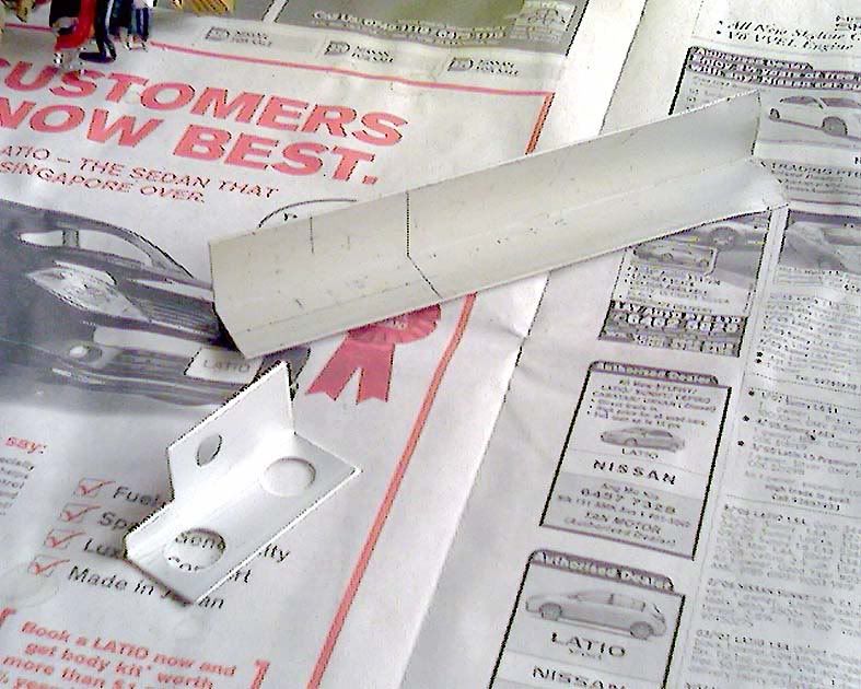 My switchable voltage divider network for the max +/- 17.90 VDC coming from the 12,000uF caps. Switch position one is for the full +/- 17.90 VDC and position two is for the reduced +/- VDC which I have not measured yet since this is never mounted. I'm starting with 5 ohms 10 W resistors as 18 ohms only gave me max +/- 12.60 VDC with shitty sound. Anyway, 10 W is the biggest resistor that can comfortably go in between that cramp space around the X-dac V3 rectifiers area. I repeat REAL CRAMP! Now I can also compare the full voltage against the reduced voltage with the switch. Heh, heh, heh, aren't I a true Zen now?  Don't attempt this cramp job if you are not Zen enough as I'm sure you will regret! Trust me!  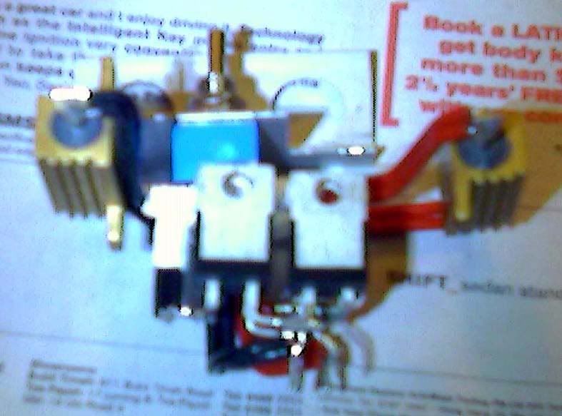 The network from another angle and so forth and so forth .................... 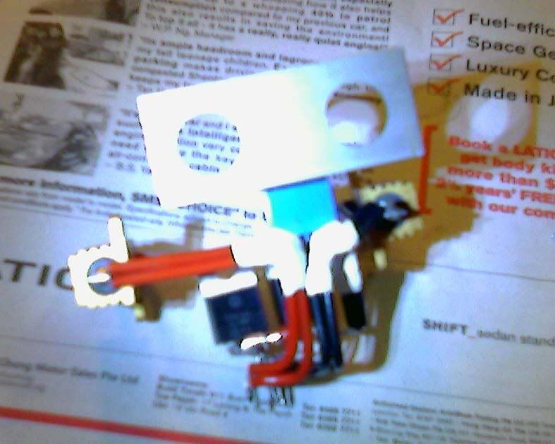 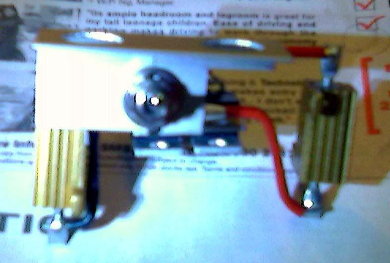 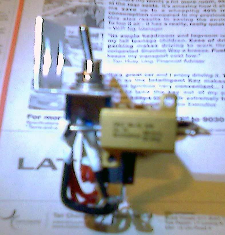 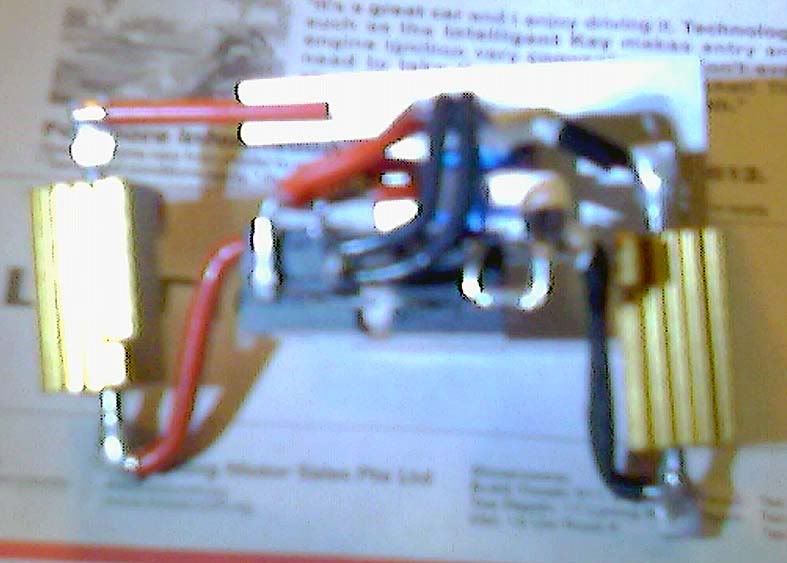 Now, I'm going to spray flat black for the mounting bracket. So have to wait until the paint dry fully before mounting the network into the X-Dac V3. Maybe tomorrow before I can show and report more .................. Wish me good luck! This is XTRProf reporting from Singapore!  Bye for now ..........
|
|
XTRProf
Fully Modded
Pssst ! Got any spare capacitors ?
Posts: 5,689
|
Post by XTRProf on Apr 19, 2008 12:29:12 GMT
XTRProf any chance you can get a new camera. I appreciate your attempt at posting pictures but they are of very poor quality. Thanks. Thanks for the feedback but I'm limited by my HP cam which doesn't have macro. I'm now currently using a Palm 750 which I had just bought less than 1/2 a year ago at about USD 650. I try to do better. Sorry. Cheers! |
|
Deleted
Deleted Member
Posts: 0
|
Post by Deleted on Apr 19, 2008 13:49:47 GMT
XTRProf Let's get one thing straight. The X-DAC V3 is NOT a shitty piece of gear, but it is my considered opinion that it is likely to end up that way, unless you use a few proven technical methods, and let Zen loose on something that deserves such an approach. Perhaps Climate change, or world oil prices, or American gun laws  SandyK |
|
leo
Been here a while!  Team wtf is it?
Posts: 3,638
|
Post by leo on Apr 19, 2008 14:08:11 GMT
Its like flogging a dead horse  All this dac needs is few things sorting out, XTRProf why not read through Alex's modding thread and do the same as what he did? the mods are proven to work and at least you will be hearing the same type of unit, I honestly don't see what the problem is. He's added more than enough drawings etc to make it easy to understand, if you struggle with anything just shout out, theres enough here willing to help. Once the few issues with this dac are sorted you can then try as much Zen as you please  |
|
XTRProf
Fully Modded
Pssst ! Got any spare capacitors ?
Posts: 5,689
|
Post by XTRProf on Apr 21, 2008 6:55:14 GMT
REPORTING PART FOURBefore I start reporting more, I will like to highlight that my HP cam pics are blur due to the no macro feature. The next 2 pictures were taken with tha same Palm Treo 750 inbuilt cam when I was at the Singapore Hifi show last year around Nov 2007. See the difference in quality when not near? I'm not trying to be funny here but to elaborate on what I had just said. Of course, I will try to better the pictures with time before sharing with all here. Feedback taken not lightly. No prize for guessing right what the speaker was and used in the demostration between LIVE singing with mic and without mic that I had briefly touched on in another post much earlier.  Hint: A very famous obscenely priced speakers from the US of A and a very famous Australian TT also obscenely priced. 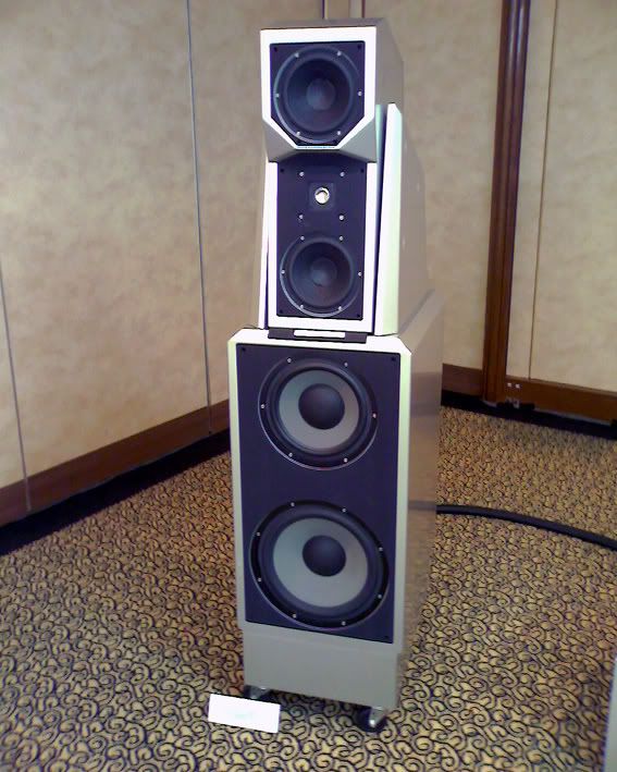 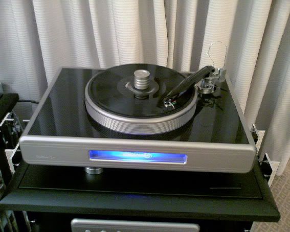 And now for the real stuffs ........................   The bracket as sprayed black and dried under the sun.  The bracket as mounted on the voltage divider network 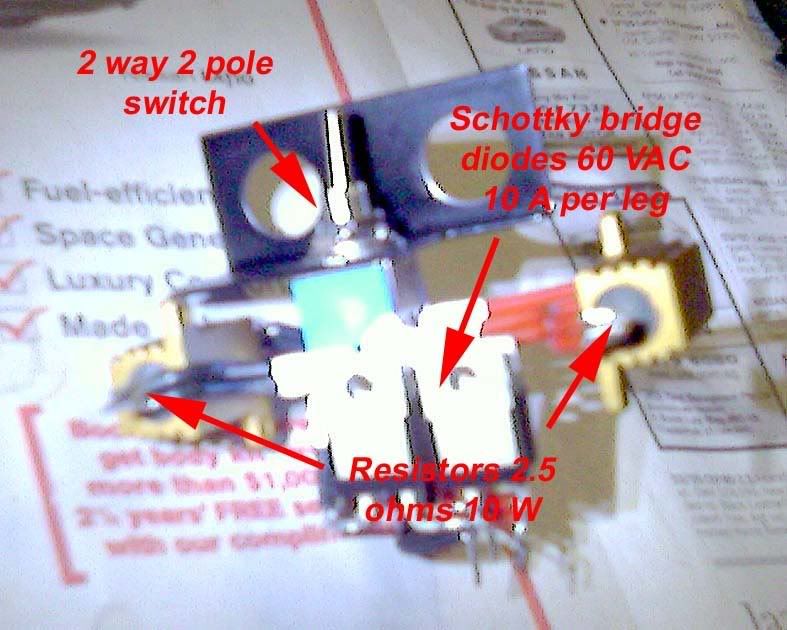 The switchable voltage divider network as mounted at the cramp bridged diodes area in the X-Dac V3. I repeat again. Working here is not for the faint hearted. You can get short circuit when not thorough in your Zen workmanship.  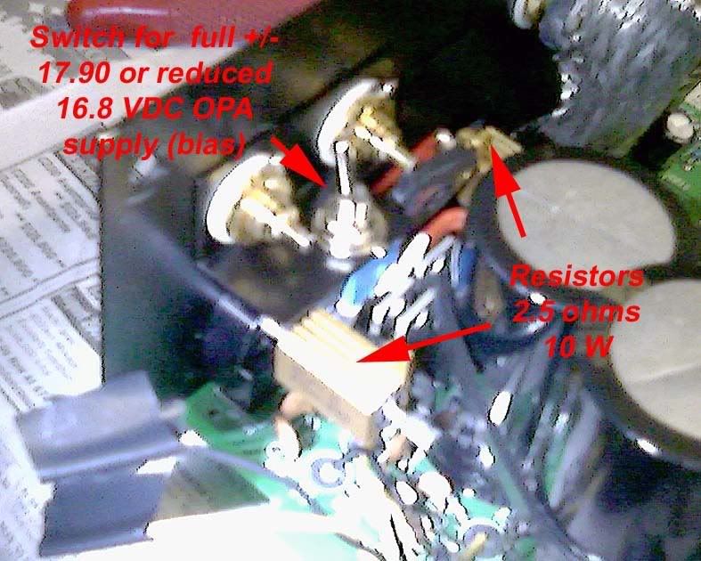 All in all, it took me about 2 to 3 hours to dress the alignment so that the network can go in between the narrow space easily and without short ciruit. During Zen listening and trial and error as well as some smart guessing, I was lucky to have to have to use only 2 resistor values before I finally arrived at the best sound. I started with 5 ohms 10 W Dale metal film resistors and the voltage were dropped to about 16.2 VDC max at the smoothing caps which were connected to the OPAs rails. The sound was much improved over the 18 ohms, as expected, as the OPAs are then working better at higher voltages then at lower. Although we may say that I had only improved the voltage by (16.2 - 12.6) = 3.6 VDC but we are tyalking of a small base voltage of 12.6 VDC here. So 3.6/12.6 = about +28.6% delta. I would say about 80% of what I'm getting without the resistors. Remember I'm using OPAs 4562 and the max recommended voltage rails are +/- 17 VDC. After listening for about half an hour with those played to death reference CDs and to get the X-Dac fully charged up, I switched over to without resistors which will give me about 17.9 VDC max. Hey, the sound improved much further. It's night and day stuffs here I'm talking about. So I decided to go for max rail voltages that the 4562 can take and that were below +/-17 VDC max. So I tried 2.5 Ohms 10 W and, bingo, I landed at 16.82 max VDC. At 16.82 VDC rails, the voltage dropped across the 2.5 ohms resistor was 0.24 VDC. So the heating power at the resistor will be around 0.24 square / 2.5 = about 0.02304 W. So the 10 W resistors used will be more than enough to handle the load. Why not the full (17.9 - 16.82) delta = 1.08 VDC across the 10 W resistors? This is because the switch, the wires, circuit copper traces, etc ,etc also have internal resistances. The sound, I will say was around 90% to what I'm getting without resistors. It seemed, I would need some run in for the resistors and 12,000uF caps before I will get almost the full sound potential. But still I don't believe it will be as good as when without the resistors. Out of curiousity, I digged at the 4562 specs again and looked at the distortion graphs. If we relook again, the distortion graph at 17 VDC rail is lower then at 15 VDC (the so call recommended voltage). So what I'm hearing was technically right. Zen and Tech shook hands on that.  Without the resistors, the sound I'm getting was a very big soundstage with layers easily delienated and the singer will sing like a true pro with emotions and feelings to the songs being interpreted extremely well. The dynamic snaps to guitar strings were you can feel the guitarists were at certain times doing it on purpose to convey the music foundation. The volume captured of the venue was very clear and the bass drum was thumping and not tucking. In other words, the ipresence and imaging were very good. However, without the extreme screening that I had done at the audio wires within the dac, there were still some sibilance and digital glare to be heard. With the screen, the vocal became very analog like and the grain and breakups that you at times can hear during heavily modulated vocal passages were much reduced although not completely gone. I hope that with the intended copper Faraday cage builds for the analog and digital sections, when I have the time, this will completely eliminate that. So hopefully this will give you a reference to what I'm talking about here. SO LESSONS LEARNT: Go for the maximum bias voltage that the OPAs can take. Better still you can achieve that without the resistors for the best sound. Anything that goes in between will degrade the sound. As in KISS, try to keep as simple and stupid as possible and I'm not joking. Also, who says that we need no screening. Bullshit! It sounded much better with extreme screening. My next stop will be most probably the analog and digital sections screening and the super E-caps bypassing to bring the PS impedance to almost 0. Let me put on my designer thinking cap then.  But now, let things run in and see how much further this simple mode goes. I have enough of moding for the moment. Let me enjoy the music again. One day, I will bring this dac to KO my friend high end dedicated Sony CDP player running thru a valve 300B SET full ranger speaker system. Heh, heh, heh ..................   That's all folks. THE END. 
|
|
XTRProf
Fully Modded
Pssst ! Got any spare capacitors ?
Posts: 5,689
|
Post by XTRProf on Apr 21, 2008 8:29:42 GMT
XTRProf Let's get one thing straight. The X-DAC V3 is NOT a shitty piece of gear, but it is my considered opinion that it is likely to end up that way, unless you use a few proven technical methods, and let Zen loose on something that deserves such an approach. Perhaps Climate change, or world oil prices, or American gun laws  SandyK Heh, heh Sandy, Who said the X-Dac V3 was shitty? Shitty in the sense of the nightmare problems, wrt to the links in my very first post here, with MF and others until I had managed to polish it to a jewel now. If, I knew it had no potential, I will not even had bought one. In fact, the X-Dac V3 is very much like a Benchmark and Bel Canto as I had repeatedly said. Don't worry. When I have the time, I will try as well to compare. I'm very open minded on this. Let me take things one at a time, can we? May the best sound be with us! |
|
XTRProf
Fully Modded
Pssst ! Got any spare capacitors ?
Posts: 5,689
|
Post by XTRProf on Apr 21, 2008 8:30:21 GMT
Its like flogging a dead horse  All this dac needs is few things sorting out, XTRProf why not read through Alex's modding thread and do the same as what he did? the mods are proven to work and at least you will be hearing the same type of unit, I honestly don't see what the problem is. He's added more than enough drawings etc to make it easy to understand, if you struggle with anything just shout out, theres enough here willing to help. Once the few issues with this dac are sorted you can then try as much Zen as you please  Ditto, as above.  |
|
leo
Been here a while!  Team wtf is it?
Posts: 3,638
|
Post by leo on Apr 21, 2008 9:36:24 GMT
Your quite unique in a very strange way Prof  Anyway as long as your happy, I guess   |
|