|
|
Post by zanash on Apr 18, 2006 9:56:39 GMT
Having open up one of these beasts it's clear to see that the four transistors in the output are cooking the pcb. There is considerable disclouration of the pcb track [tranies using these to sink heat away from themselves]. If this is left unchecked it may cause failure of the unit.
I think this has been mentioned before and a recomended rs part 507-4753 was sugested.
I've bought this up again ...as a heads up
Anyone who has this unit should check it out.
|
|
Fergus
100+
Done a David Ike and is now known as Godkin 
Posts: 197
|
Post by Fergus on Apr 18, 2006 13:21:29 GMT
  What is it with MF's X-series and its tendency to cook PCBs?  My X-CAN V3 is very nearly overdone and now my X-10 V3 promises to do the same. Against MF's stated recommendation, I leave my X-Components well and truly off. Fergus  
|
|
rickcr42
Fully Modded
Rest in peace my good friend.
Posts: 4,514
|
Post by rickcr42 on Apr 18, 2006 14:08:57 GMT
going for the unique "look"
take the same boards and unstack them in a larger enclosure and the problem would cease but then you would not have an "X" componant with its own stand out style.
You either get small and hot or large and cool.Heat likes escape routes
|
|
|
|
Post by PinkFloyd on Apr 18, 2006 21:11:28 GMT
X-10V3 is a line buffer Rick and it's a one PCB job in a relatively spacious enclosure (well, spacious compared to the X-CAN V2) Here is one I modded earlier: 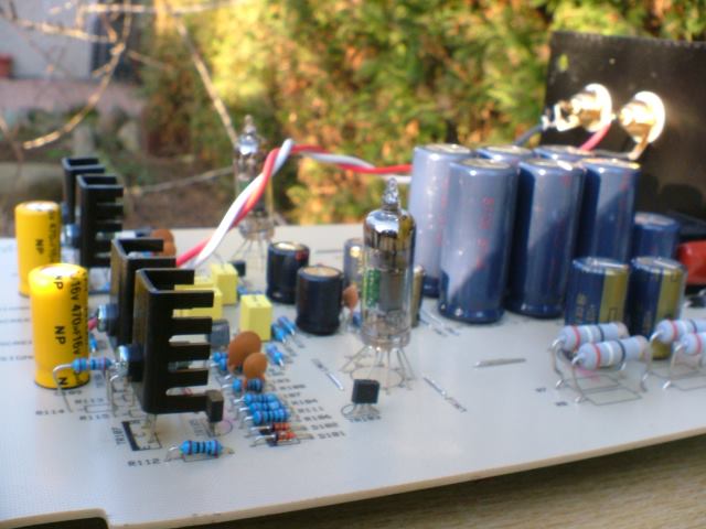 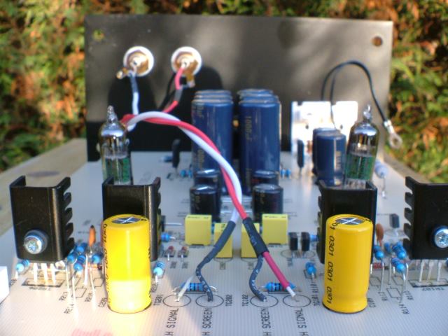 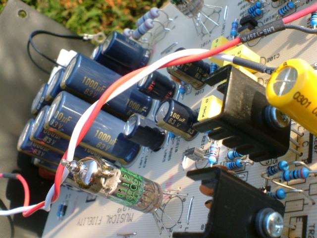 |
|
thegreatroberto
100+
The Great Roberto "himself" The real deal on a stick!
Posts: 157
|
Post by thegreatroberto on Apr 18, 2006 21:18:12 GMT
Ah...............RS are out of stock of these.Have you bought them all up Mike ?
|
|
|
|
Post by PinkFloyd on Apr 18, 2006 21:47:42 GMT
Ah...............RS are out of stock of these.Have you bought them all up Mike ? I wish! Out of stock until June they reckon. I've just noticed an e-mail from you Rob, will reply shortly. Mike. |
|
rickcr42
Fully Modded
Rest in peace my good friend.
Posts: 4,514
|
Post by rickcr42 on Apr 18, 2006 21:50:25 GMT
looking at that board Mike I do not see any "hot spots" even remotely possible so what are these "cooking" or scorch marks I keep hearing about ?
Heat sinks under rated ? Are they uncomfortable to touch for more than a moment when in use playing music ?
Just curious mike.I obviously do not have any "X" audio devices in my possession so no real first hand knowledge
|
|
Stormy
100+
Advocates putting smokers in a "Sin Bin"
Needs to learn to keep his big mouth shut.
Posts: 153
|
Post by Stormy on Apr 18, 2006 23:02:52 GMT
I think the issue is that the heatsinks are under-present in standard trim. MF don't seem to bother with them, and just let the transistors use their in-built metal bit to radiate heat. The X-Can V3 is probably more of a problem than the X-10 by the look of things, as it has two transistors bolted together in each position so they share their heat and lose some radiating surface area. Apparently some people are still experiencing problems with scorching, even with the heatsinks fitted. I suppose the best advice would be to use the biggest heatsinks you can fit inside (tall thin ones seem to fit best), and make sure you've got a really good thermal path from the transistors. Failing that, you could borrow Rick's fantastic idea of bolting the transistors directly to the inside of the case somewhere and running wires from their legs to the PCB. That's about as big a heatsink as you're going to get without changing cases. Maybe you could bolt a piece of metal between each transistor and the case instead - it's a toss-up between short heat paths and short electrical ones. The big problem with these ideas is that (as we know) the transistor casings are not at the same potential, and don't like being shorted (Pop!), so you'd have to electrically insulate all the transistors from the case in the same way (as you ideally should also do with individual heatsinks). |
|
thegreatroberto
100+
The Great Roberto "himself" The real deal on a stick!
Posts: 157
|
Post by thegreatroberto on Apr 19, 2006 6:36:14 GMT
I could show you boys heating in an X-can V2 !
The one I bought showed significant heating around the TIP trannys under the PSU.Especially after it developed " maintenance induced defect"..........i.e. one of my soldering cock-ups.Anyway cock-up now sort of fixed and new fault has been found.One channel ( the one under the psu ,left channel) gets the TIP trannys so hot that you can't touch them after being switched on for 5 seconds.All this current has "burnt" the two smaller trannys on the upper board as well !
Anyway these "burn" marks are the result of faults rather than inherent poor design.Although, I believe that these X-cans require some sort of forced ventilation.I favour two 1 inch dia. holes in the rear panel of the 'can.I'm trying to find a small 1" dia 12V fan to bolt on the lower hole.
I know Mike quite favours drilling 2 holes in the top of the aluminium casing, but that's a bit too severe for me !
|
|
|
|
Post by zanash on Apr 19, 2006 7:34:41 GMT
Further to the info provided I 've now measured the temp after five minutes and the transistors have reached 80 degree C and the stand off resistors are very hot too 50 ish C.
|
|
|
|
Post by zanash on Apr 19, 2006 7:41:15 GMT
Nice mods ....
Why have you not done the resistors in the output ?
or swapped the truly bad rca sockets on the input?
I'm not going bipolar ...I've had very good results with silmics [round the right way !]
You also seem to have kept the wet string ?
Ok so cable sceptics may not like to hear[pun] but a change to silver in ptfe opens up the sound to a large extent [nearly said night and day .....ooops] in empirical terms 10-15% more than the icing on the cake.
Did you use panasonic fc through out ?
I don't have any caps near the right value and was wondering what to go for.........
|
|
|
|
Post by PinkFloyd on Apr 19, 2006 9:32:33 GMT
Nice mods .... Why have you not done the resistors in the output ? or swapped the truly bad rca sockets on the input? Why not paint the entire thing with gold leaf whilst I was at it? No, seriously, the guy I modded it for only wanted the caps done and he was absolutely "over the moon" with the mods and I quote: " I was not prepared for the sound from theX- D10 V3. I have just had a listen and to be honest it is astounding. The difference from before is amazing as whilst it made some improvement, nothing like it does now. If this is what you can do with the D10, what could you do with my MF 308CR preamp & power amp? Now there’s a challenge!" That's Rob Farnell's take on the mods (a member here feel free to ask him) and I agree with him, the cap mods are "astounding". With mods, the law of diminishing returns usually starts to kick in (and the price sky rockets) when you start over egging your pudding and throwing in "unnecessary parts into the mix. Believe me, I have tried uber expensive RCA chassis mount sockets in place of the gold plated (stock) quad sockets and they make no difference at all to the sound.... "NO" difference at all. When you say "why have you not done the resistors on the output" what do you mean? "done" what? This is another area I have listened to "in depth" and yet another area where the law of diminishing returns kicks in big time Zanash. Directional electrolytics in the signal path are a big no no (silmic, black gate, cerafine... call them what you want!) in fact "any" caps in the signal path are a big no no but, in this instance, to ensure protection against DC they're essential in the circuit. Non polars are definitely the way to go here Zanash. I've been experimenting with different flavours of caps for many years and (to my ears) a non polar output cap bypassed with two film caps (a polyprop and a polyester / silvered mica) beats a polar cap (sonically) hands down. A silmic, a Black Gate, a Cerafine, a Panasonic FC will all sound smeared in this position.. I've tried them all, "extensively" in the X-series, the Graham Slee Solo prototype and all three versions of the WNA headamp. Just chucking in an exotic looking (or exotic sounding) cap into the circuit doesn't always reap rewards and, in some instances, can actually make matters worse. A silmic as an output cap is probably the worst possible cap you could use IMO. Most certainly! I have also kept the very thin copper traces on the PCB. No intentions "at all" to turn the unit into a parking bay for boutique parts, everything I have done has been done because it brings the best sound out of the unit, there are "no" unnecessary money wasters in my mods Zanash.. I'm all about maximum sound for your pound and tend to concentrate on the areas that bring maximum "very noticeable" improvements to SQ. As I say you can totally (and unnecessarily) over egg your pudding and end up throwing silly money into things with no gain sonically. You've tried this in your V3 then? Yes. They add a good 90% icing on the cake in "empirical" terms. For the output caps I used the very capable (and very reasonably priced) Nitai 470uF Non polars bypassed with evox rifa 47nF polyprop and WIMA 220nF polyester (much listening and much cap rolling this combo sounds GREAT) 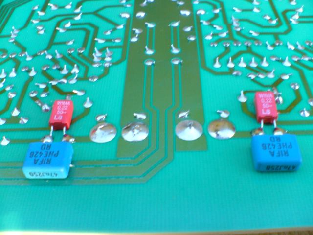 Output cap bypassing |
|
rickcr42
Fully Modded
Rest in peace my good friend.
Posts: 4,514
|
Post by rickcr42 on Apr 19, 2006 14:49:10 GMT
pretty extrmeme actually and one that IS shortening the life of your amp so will need to be addressed. Couple of "thinking out loud" points : 1-Fan noise is a serious problem with audio gear and some of my former Class-A speaker amp experiments in this area (an attempt to keep cost down,heat sinking is very expensive,and chassis size reasonable,class A is HUGE mostly) were of the "driving me fkng nuts" variety when the fan would intrude on low level passages using 96dB/1 watt/1 meter efficient speakers. Straining forward to hear music content you KNOW is present but losing the battle because the fan noise is masking it even though that noise is steady state and very low in actual volume level.It don't take much to lose the little things. The "fix" for me was first running the fan at half speed.That is where I used a fan rated for 220VAC on my 120VAC line.The combination of forced air and "almost" adequate heat sinking cooled things greatly but brought in another "new" set of problems,one of which was dragging all manner of airborne crap into the amp making a monthly "cleanup" part of a regular routine. Eventually I reworked the entire chassis structure taking a page from the early 1970s GAS Ampzilla 200WPC MONSTER which used an ingenous combination heat sink/fan " chimney module" for the output and bias tracking circuit. Another take on this but in a horizontal "fan assisted tube" rather than a vertical "chimney" is the A-40 Class-A amp by Nelson Pass,also from the 1970s  These pre-date the CPU as a common device but you can see resemblances to how the modern Pentium chips are cooled.They took a page from the Class-a audio amp arena where you either added serious amounts of very expensive,very large and very heavy heat sinks or you reduced the "metal" and upped the air flow with fans or in some cases (SUMO Nine Class-A) both. Mine DIY answer was slots cut into the bottom of the chassis,good sized heat sinks facing "fins in" with the mosfets mounted to the inner side then a fan on top drawing air up and out from the bottom vents.The fan being both high quality ( Pabst) plus run at 1/2 speed meant very little if any intrusion into the music. Fast forward this to the headphone amp arena and I would think a 12 VDC computer fan,no cheap shit here guys but full metal ball bearing operation for a long trouble free life,but run at 6 VDC in combination with having headphones ON which also buffers the sound would likely work for extreme cases. If this is to be a horizontal mount,that is with the fan hanging off the back,the true best location for the vents would be the front panel but I don't think too many are willing to bite that bullet so towards the front and at the sides would be a fairly good comprimise. METHOD # 2 :For the real "DIY MANIAC" I think a total reworking of this area is the answer. Pull the transistors totally,get them onto a sub-board so you can get some clearance back then bolt on some serious heat sinksLooking at the pictures only I see where any REAL heat sink would hit and rub other parts which means as the heat is transferred away from the active devices anything the heat sink touched would act as if a heat "wick" and could in extreme cases deform/damage/change parts.You heat a resistor enough and it can change in value.you heat a capacitor enough and the dielectric melts which again changes its basic nature into something else. A tip on heat sinks is the more FINS you have going in many directions the more actual cooling you get so when you see those heat sinks that look like two "X"es connected by a center bar (looking down from the top) you are seeing an attempt to get the maximum amount of cooling into the minimum amount of space.I personally would pull the entire output stage and make a new "bolt on module" using a mini perf board for all the output componants with the exception of the coupling caps.The reason for the approach is the nature of any bypasses or oscillation prevention resistance which ONLY work if they are right at the transistors.Anywhere else and they are just "there' while accomplishing nothing a couple of these (enlarge holes for the transistor)  and a couple of these 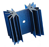 and I think a fan would not be needed as long as there is venting somewhere. Jus thinking out loud as I said earlier folks but I find conversation and ideas lead to other ideas which lead in the end to solutions |
|
thegreatroberto
100+
The Great Roberto "himself" The real deal on a stick!
Posts: 157
|
Post by thegreatroberto on Apr 19, 2006 18:19:19 GMT
I was thinking more of something just to "move" the air through a lower hole in the rear of the can and exhaust it in the upper hole.A 12V fan similar to those used in a PC but smaller.Nothing that is going to make any real noise. All these heatsinks inside the X-can are fine, but it still relies on natural cirulation to transfer the heat from the heat-sinks to the casing.I'll see if I can source a small 12V. The set of trannys that get the hottest are under the PSU board.The psu board does not allow the circulation and hence the cooling.Most V2's show the signs of burning here.The fan idea with two holes would cool these first before cooling the front set of trannys and then exhaust out via the top hole.I really can't see another method,unless you drill a couple of holes Mike style in the top of the casing  What about this for a starter www.rapidelectronics.co.uk/rkmain.asp?PAGEID=80010&CTL_CAT_CODE=&STK_PROD_CODE=M30765&XPAGENO=2 |
|
rickcr42
Fully Modded
Rest in peace my good friend.
Posts: 4,514
|
Post by rickcr42 on Apr 19, 2006 18:50:54 GMT
maybe can you drill 1/8 inch holes right at the offending parts so that even though mounted below there will be flow upwards (heat rises,does not go sidewys unassisted) better the one that uses 24 volts and run it at 12VDC "half speed" for the ultimate in quiet.You also want to hook it up so that is DRAWS OUT and not pushes in.that is the only way to get actual air flowing through the casing thus cooling. If back panel mounted (seems best) I would put a "slot" towrds the front panel right where the "feet" join the case.You want this to be low yet unobstructed if possible. Yeah but are you gonna listen to a guy who beat the crap out of a pair of BUF634 buffers with a hammer on a cement floor ?   ;D   |
|
Stormy
100+
Advocates putting smokers in a "Sin Bin"
Needs to learn to keep his big mouth shut.
Posts: 153
|
Post by Stormy on Apr 19, 2006 19:16:34 GMT
Bleurgh - fan cooling. I'd avoid it unless absolutely necessary because the whirr will slowly drive you nuts. Smaller fans produce a sound with more high-frequency content than large fans, so they're often more noticeable. That and large fans don't need to spin as quickly to shift the same volume of air, keeping the volume lower anyway. If you want REALLY quiet 12V fans, I'd recommend something from this site: www.quietpc.com/gb-en-gbp/products/casefansI have two of the 80mm "Dustproof" fans in my computer, and run at 7V, they're allmost inaudible. They do smaller ones as well - don't worry. Highly recommended, depite the hefty price tag. Rick's right about 24V fans if you can find them easily. Not only are 24V fans very quiet when run at 12V, they are also generally slightly quieter than their 12V airflow-equivalents when run at full voltage, so you are starting from a better place. Not all fans will actually start spinning at 50% voltage, but once they're going, almost all will continue to run - this is why a lot of good motherboards/fan-controllers give the fans a quick burst of full power when you initially turn them on before dropping to the "necessary" voltage. Make sure any fans you do use are decoupled from the chassis with silicone rubber gaskets/gromets or rubber/foam "screws" - the resonant/vibrational noise is always much more obvious than blades on air. |
|
thegreatroberto
100+
The Great Roberto "himself" The real deal on a stick!
Posts: 157
|
Post by thegreatroberto on Apr 19, 2006 19:52:40 GMT
In the first instance, I think I'd locate the fan a few feet from the X-can, and use some suitable ducting to draw the air from the top hole.Yeah, I know it'll look shite but at least there is less chance of getting the fans noise transferring to the case of the X-can.First thing to do would be to make up a new rear plate.I'm not drilling the rear panel of my X-can yet....................Or maybe I can rip out the fan in my Dell Inspiron 6000 that I'm using and try that !
|
|
|
|
Post by PinkFloyd on Apr 19, 2006 20:04:31 GMT
Covered this angle already Rick, it helps www.rock-grotto.co.uk/v2cooling.htm Thing is, you'll only ever hear from the guys who have scorched boards.. you'll never hear from those that don't have any heat problems at all. I've seen a few of the scorched jobs but my own personal stash runs as cool as the proverbial cucumber. The 10R resistors could be the culprit here and maybe going to 12R would solve the problem. I remember with the WNA that if you went from 10R to 8R those transistors would get REALLY hot. 10R fine but 8R = HOT. I will experiment with this theory @ the weekend and will fit some different values of resistor in and measure the core temp. of the transistors. Have a look at the V2 schematic (I know it's not 100%) and see if you concur with this Rick. Maybe even 11R would be enough to just take the edge off. Mike. |
|
|
|
Post by PinkFloyd on Apr 19, 2006 20:09:30 GMT
Fan cooling?? It's a line buffer not a fickin' 1KW power amp  |
|
|
|
Post by zanash on Apr 20, 2006 6:28:13 GMT
Back to 10x3 mods .....
I can get 4n silver 0.5mm for about a £1.50/m ptfe comes in at 50p/m .....so replacment of the wet string ....cost £2 now I'd hardly call that boutique. that 1m should rewire the whole unit. Sockets at a £1 each. The real cost is the time required to prepare the silver and sleeve before being cut to size and fitted. I did the short cut with signal path using the above materials and also replaced all signal path resistors with 0.1% dale vishay's, and all elec. caps are bypassed with 1uf wimas. ....this produced noticable removal of mush from the sound.
Though this is not my unit......I've a free hand in modding [following discussion with the owner] I'm still left a little cold by the x10. Its sounding much better than before cleaner faster,better imaging huge sound stage..etc But I'm suspecting that its the valves themselves who's sonic signitures are a little at odds with my tastes. I'm getting a nassal congested sound in the upper mid......
Now the owner has the xpsuv3....but has sent me the wallwarts, for obvious reasons. I'm assuming that this unit will open up the sound further.
Modds still to do.....
I've ordered a shed load of FC caps for the psu section....
I'm waiting on heat sinks...
I was going to damp the casework but at oresent it runs too hot for the soft bitumin panel to stick....though I may fit some to the base, out of sight.
Is there any thing that you can suggest that I've not done and really ought to ?
|
|
|
|
Post by PinkFloyd on Apr 20, 2006 9:38:37 GMT
Cheap.. "until".......... Yup! now it's not so cheap if you value your time at say £50 per hour is it?  Be careful and don't just bypass for the sake of bypassing Zanash. You may find that just "one" bypass cap sounds worse than say "two" or three in parallel as it "may" resonate at audio frequency. Frenzied bypassing of everything can, in some cases, make the sound a lot worse. The panasonic FC are very low ESR and really don't require bypassing as their HF properties are excellent compared with caps 20 years ago, if you "must" bypass then rewards can be reaped by bypassing the non polar output caps. Remove the Wima bypass caps (seriously) You assume wrong. The X-psu is just a toroidal in a box and the improvements are NEGLIGABLE to say the least. The regulation takes place onboard the X-10D (not inside the X-PSU) so concentrate on the inside of the V3, the wallwart is pretty representative of what you'll hear with the X-PSU. No need to damp the enclosure. If you "must" damp then simply place the X-10D on a foam mat (an old mousemat will do) works wonders, try it! Yes. Don't over egg the pudding  |
|
|
|
Post by zanash on Apr 20, 2006 19:59:48 GMT
I do agree with you ........to some extent.
Each mod has been listen to ...ie after say each pair of caps has been bypass
I'm relatively lucky being able tell if things sound better/ worse/ different at a quick listen.
The pana FC's have removed the nassal twang so I score that as a big plus....
Still I'm concerned by the case ...using a stethescope you can hear it ring when music is played in the same room...as valves are microphonic they must be picking something of this transmited energy up ....
I've built sofisticated anti resonance bases of other item of my gear ...I prefere stiff with a constrained layer to mass and spikes....rather than mouse mats I use foamed butyl rubber which is a cheap mans sorbothane but does not kill the vibrations quite so well.
I'm going to tackle the heat sinks tomorrow !
|
|