|
|
Post by divad68 on Aug 24, 2006 22:53:24 GMT
Hi, I've had one of PinkFloyd's V3 capacitor upgrade kits for months, but have only got around to installing it this evening.
Everything went fine except for the fact that I forgot to install the 470uF caps on their side, meaning that I can't refit the front panel. I now need to order 2 more 470uF 105deg (16v) caps so that I can try again! Problem is that I think the ones that came in the kit are no longer available on the RS website.
Please can someone advise which ones of those available I would be best buying. NB: I tried posting a link to where my search got me to on RS, but when I pasted it in it was far too long!
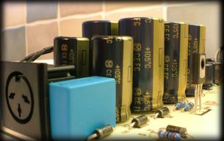
By the way, I did manage to fit those blue 0.47uF caps, either side of the power connector, but they were a real tight fit. I couldn't insert them fully as some other components are in the way. Because of their size they also get in the way of the 1000uF caps adjacent to them, which I therefore had to bend inwards to allow everyhting to fit. Works though!
|
|
|
|
Post by PinkFloyd on Aug 25, 2006 10:41:59 GMT
Hi, I've had one of PinkFloyd's V3 capacitor upgrade kits for months, but have only got around to installing it this evening. Everything went fine except for the fact that I forgot to install the 470uF caps on their side, meaning that I can't refit the front panel. PM me your address and I'll send you a couple of 1000uF ones free of charge, no worries at all. See above. Oh yes, they're a tight fit or should I say more of a "perfect" fit. You shouldn't have to bend the 1000uF caps, it's more a case of adjusting the .47uF cap's legs until they are a snug fit between the 1000uF's and the DC inlet socket (see picture) they really are a "perfect" fit but you have to spend a minute or two getting the offset and "pitch" right with the legs for them to plunk in exactly where you want them to on the board. To make it slightly easier you can bend the two adjacent diodes on the board outward a bit this will allow the .47uF to drop closer to the board and also give you a bit more leg to play with. Here it's a case of thinking "before" acting and doing a dry run to ensure it'll fit "before" soldering into position. The instructions clearly tell you to lay the output caps on their side  No worries, a replacement pair will be in the post. Mike.    |
|
|
|
Post by divad68 on Aug 25, 2006 14:51:48 GMT
Thanks ever so much Mike.
I did actually study the instructions, knew exactly what to do, but then forgot to do it..duh!!
PM on its way.
Cheers
David
|
|