|
|
Post by PinkFloyd on Apr 12, 2011 20:07:16 GMT
12th April 2011 - Neil Gallagher's X-CANS (V1) ALPS pot, Jalco headphone socket, DIP 8 opamp sockets, New quad gold plated phono socket, Ceramic valve sockets.... blue LED still to be fitted and opamp will probably be OPA2227. WIMA MKS4 film caps, WIMA polyprops, Panasonic FC 1500uF, Panasonic FM 1200uF, Samwha VA, OSCON SC, UF4001 diodes. 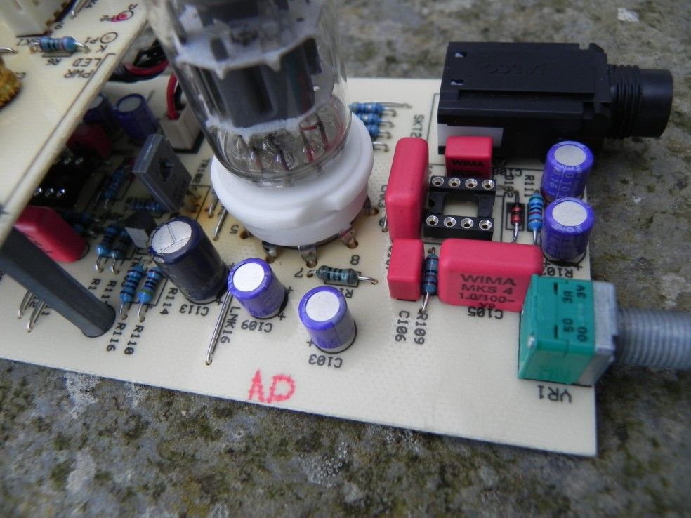 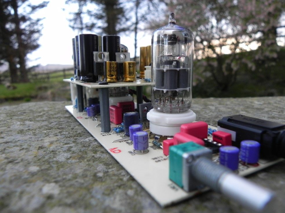 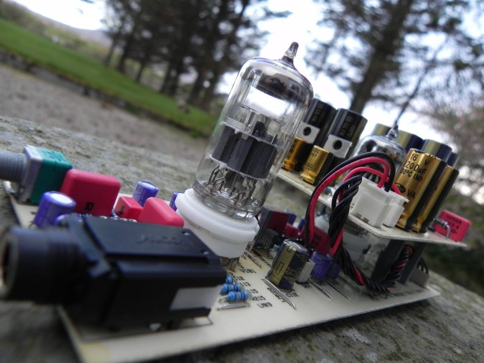  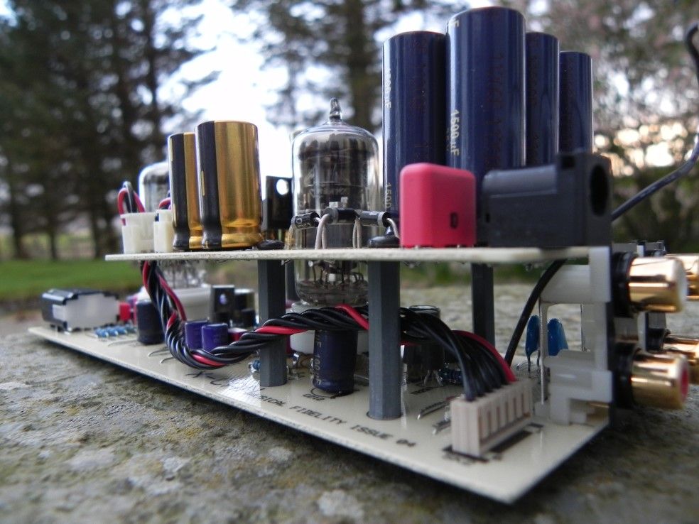 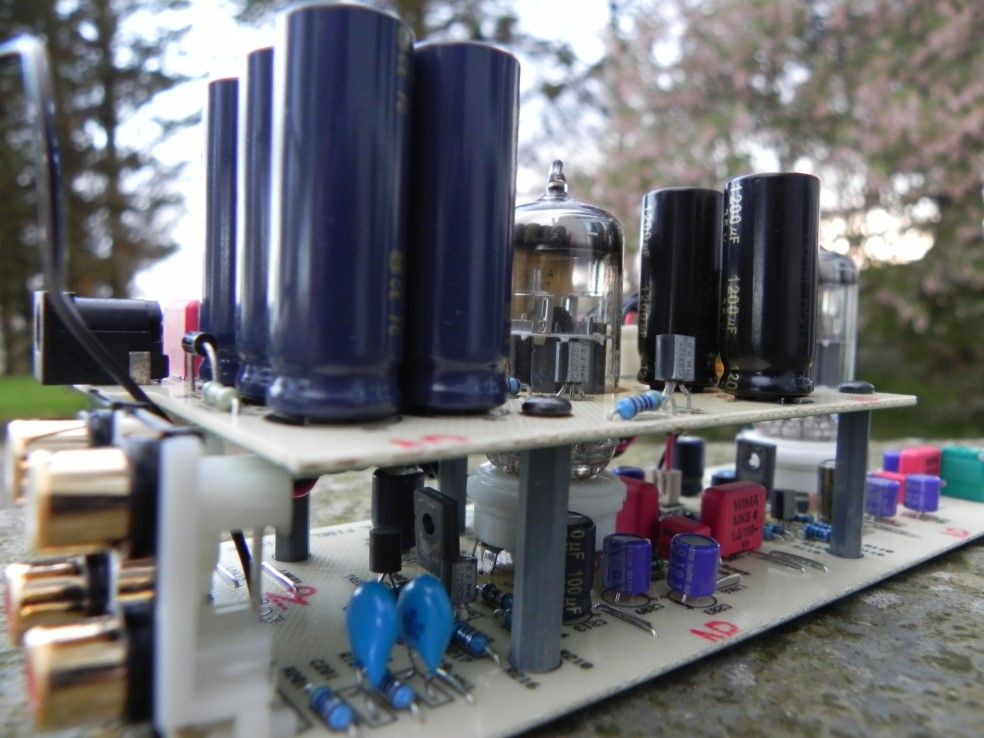 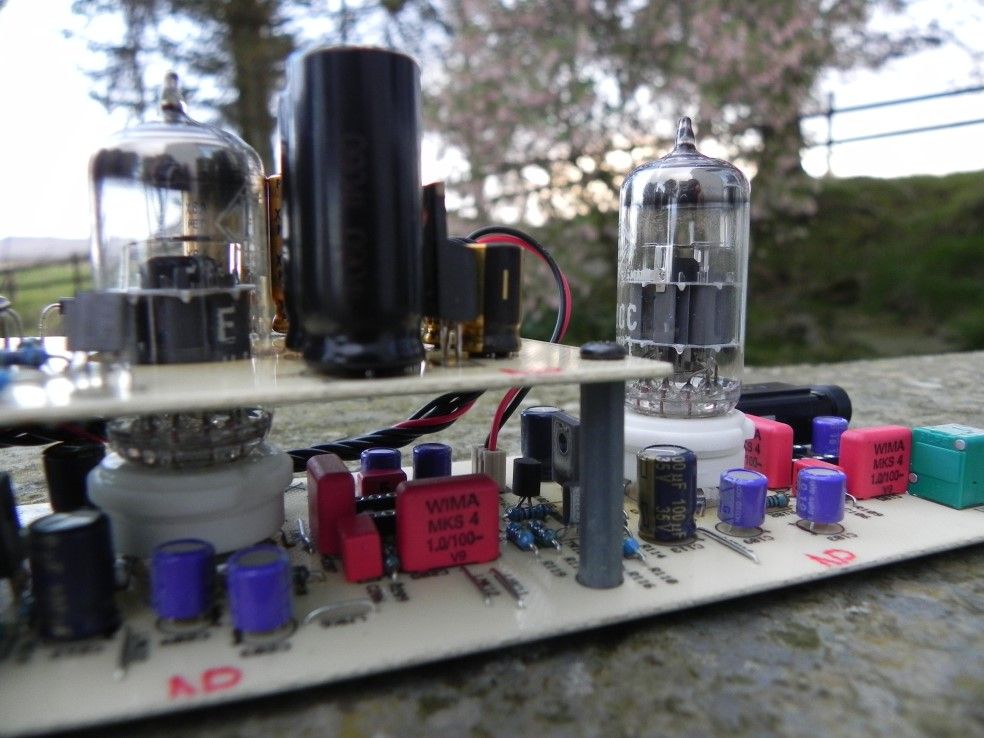 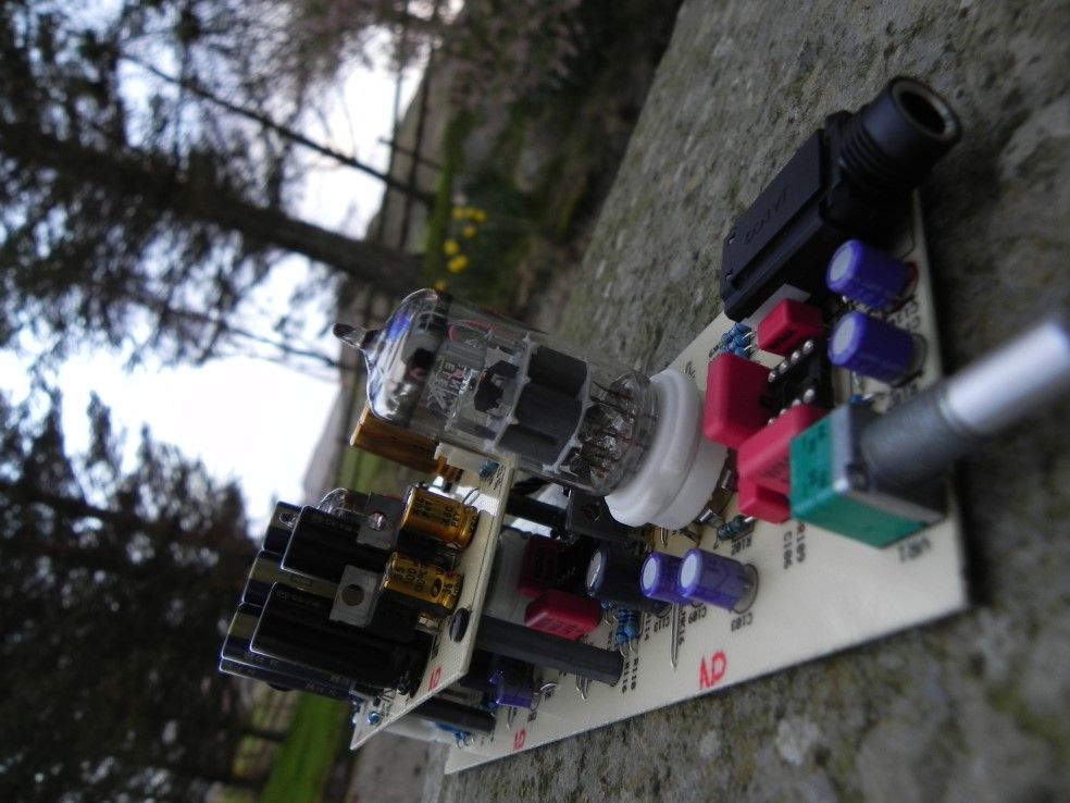  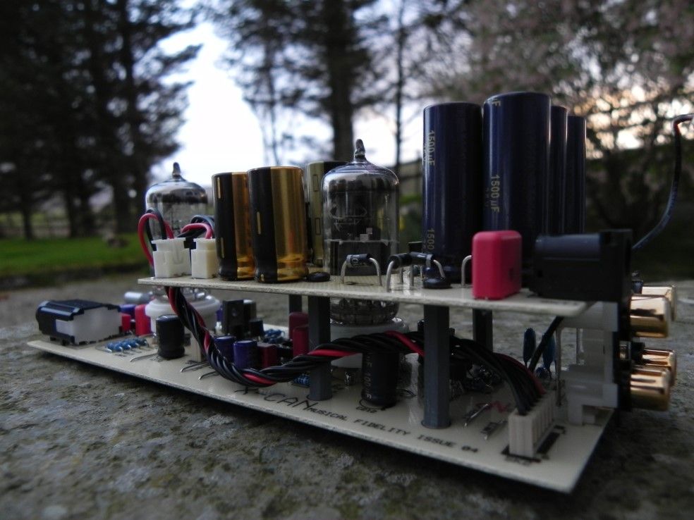 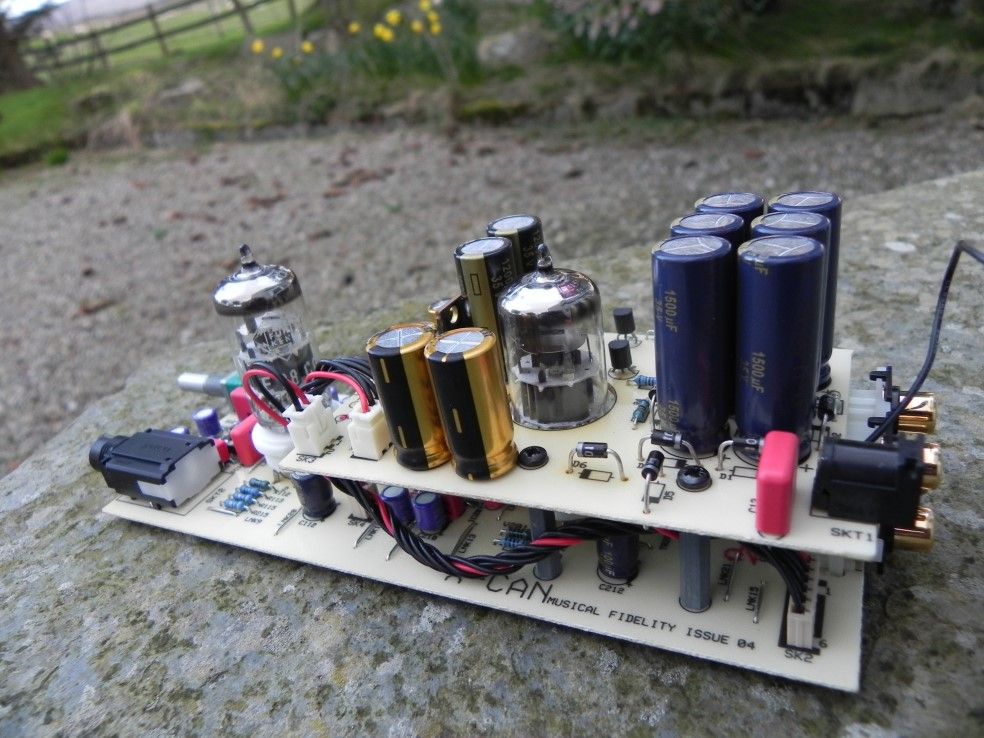  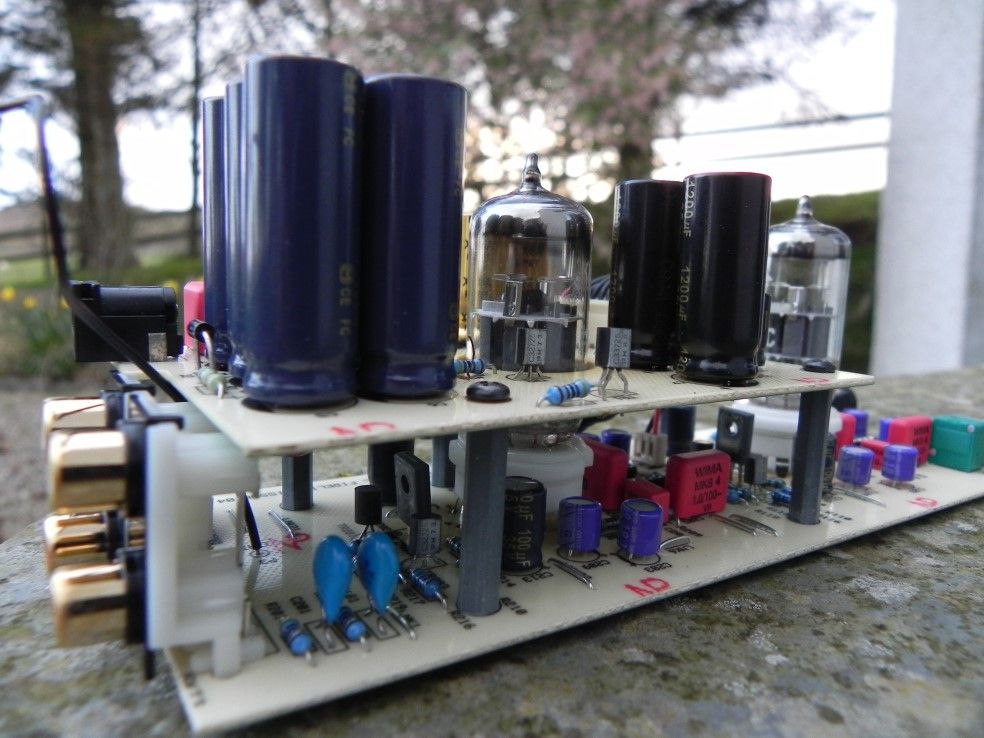 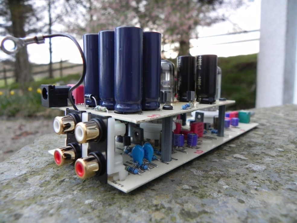 |
|
|
|
Post by PinkFloyd on Apr 14, 2011 20:31:23 GMT
14th April 2011 - Neil Gallagher's X-10D Remove the crap.....  Give the board a clean.... 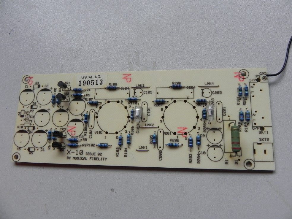 Add some UF4001 diodes (ultrafast).....  Add a 6K8 resistor (for the blue LED) 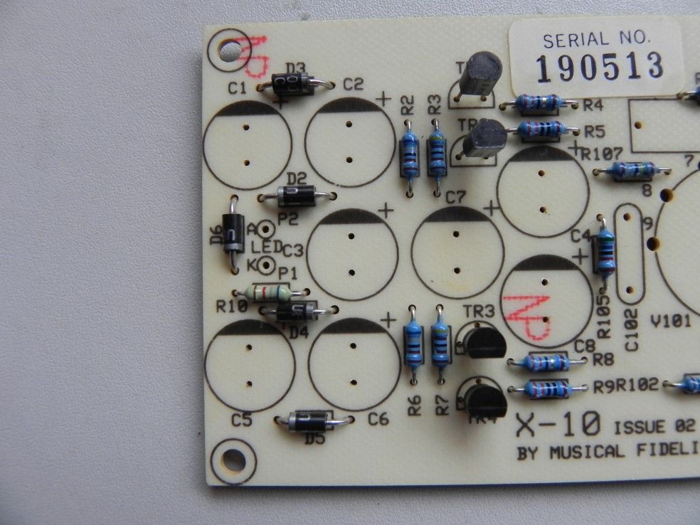 What about a nice brand new DC socket?.......  Replace the 220nF coupling caps with WIMA 1.0uF......  Fit a couple of ceramic valve sockets..... 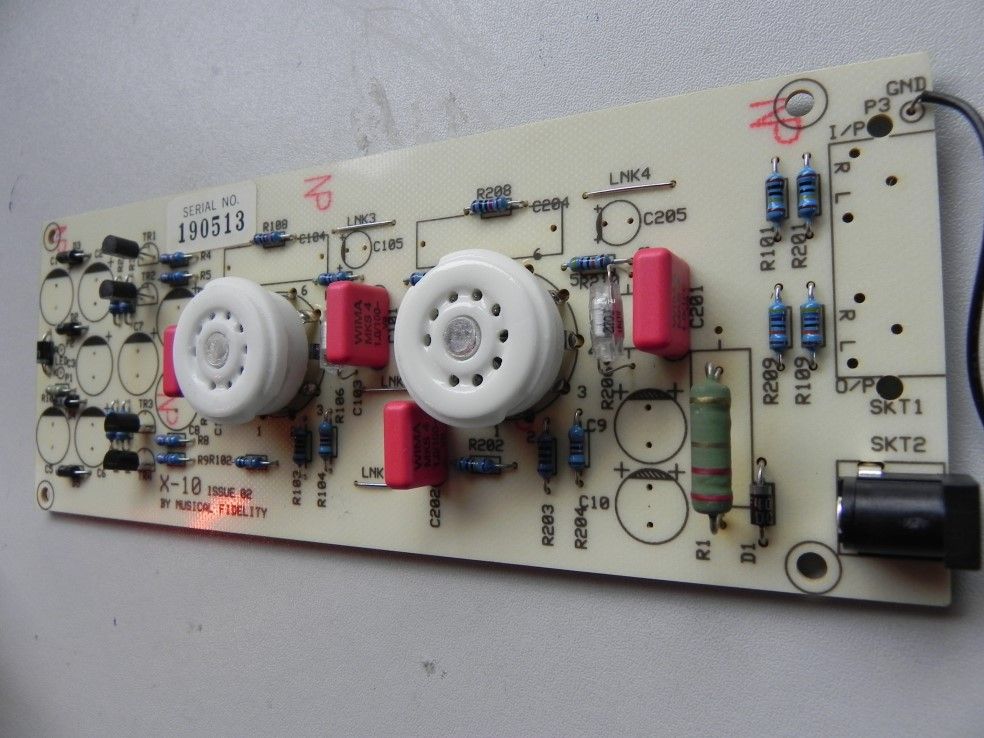 And a couple of OSCON caps...... Replace the 2.2uF coupling caps with 4.7uF polypropylenes.....  A couple of Samwha VA caps......  Some Panasonic FC / 1500uF...... 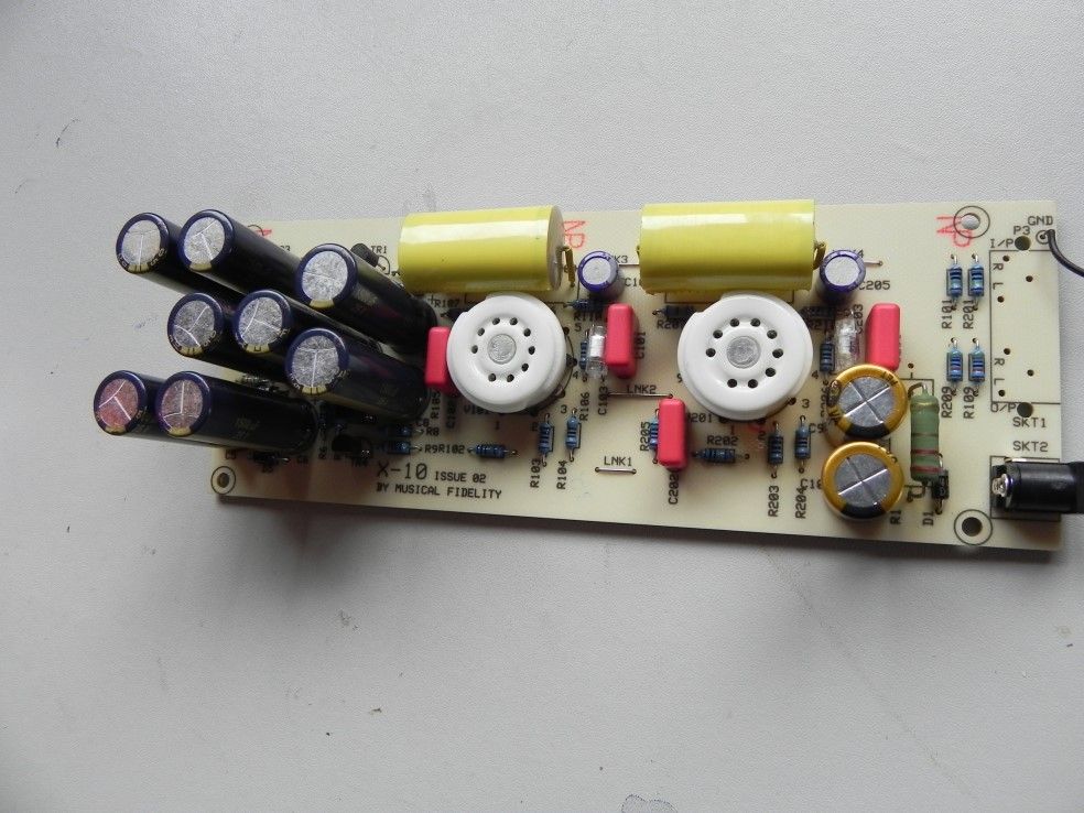 A nice new gold plated quad phono socket...... 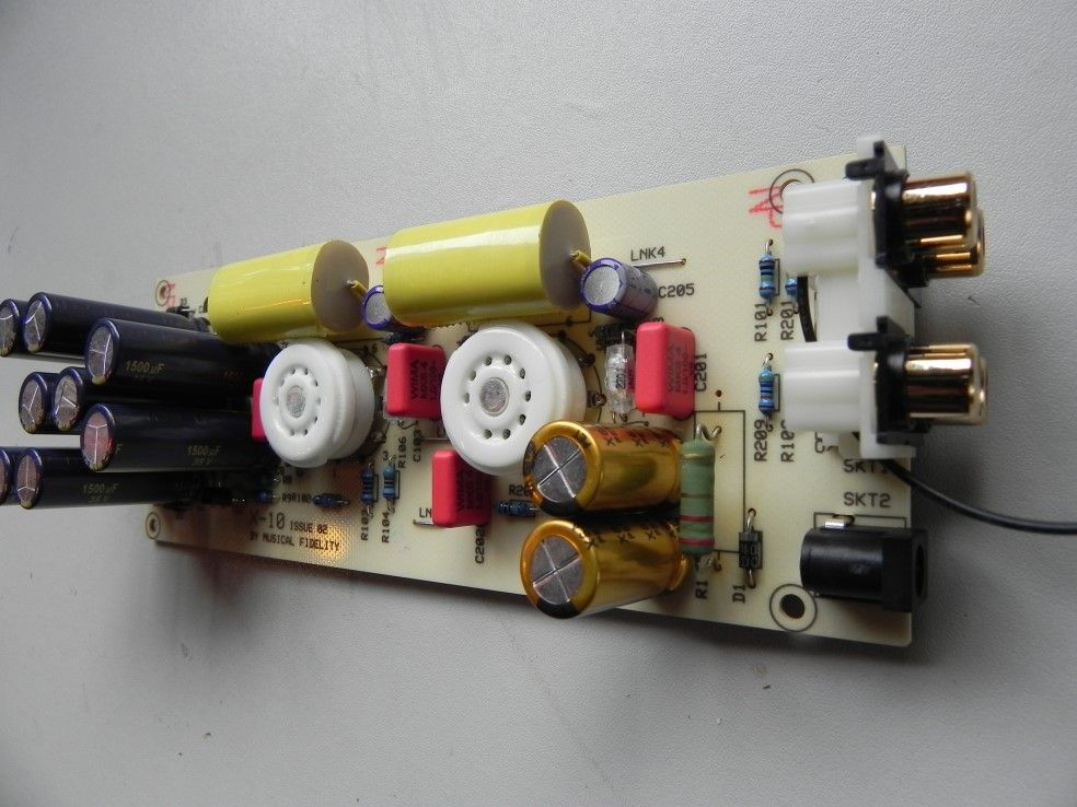 As good as new  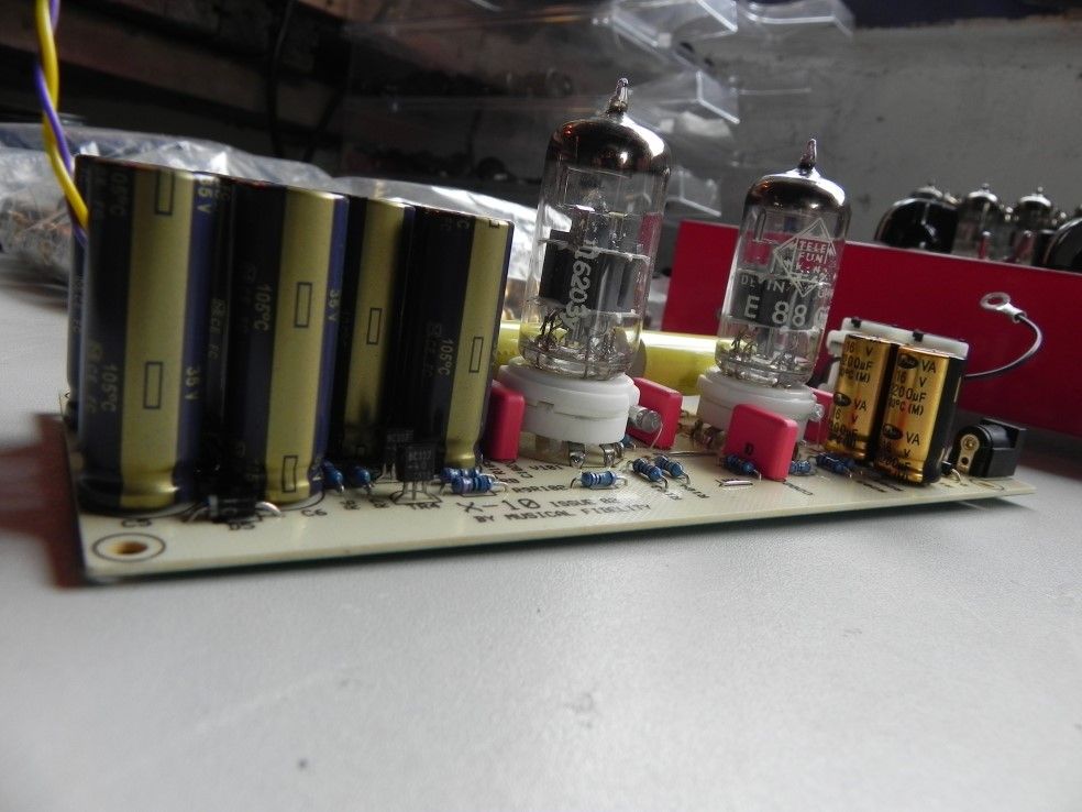 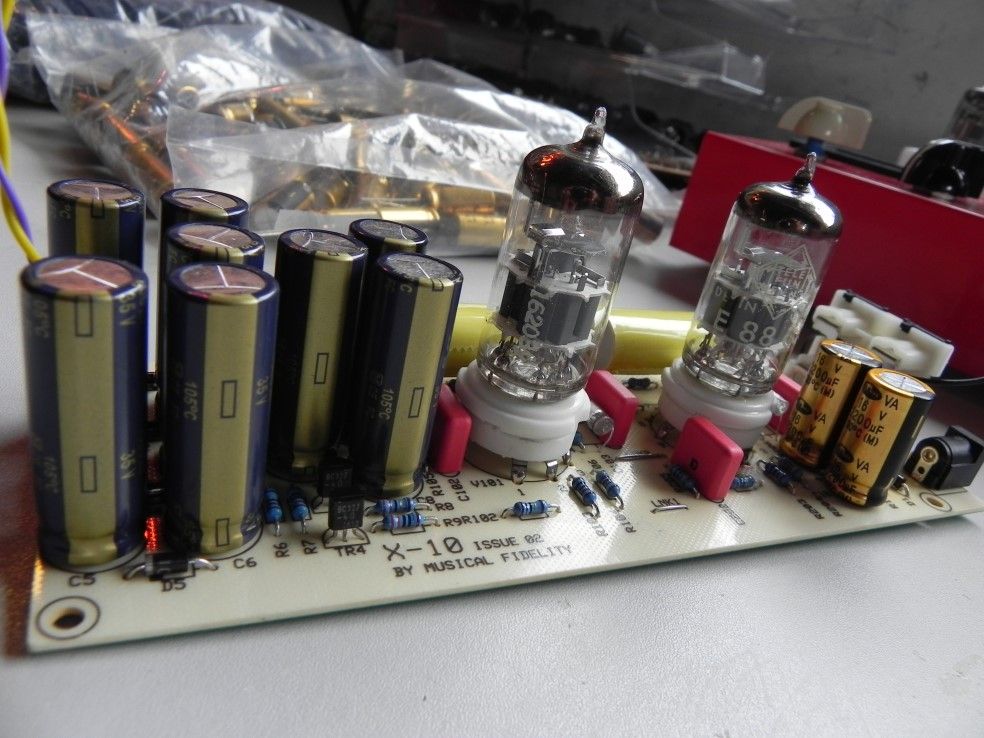 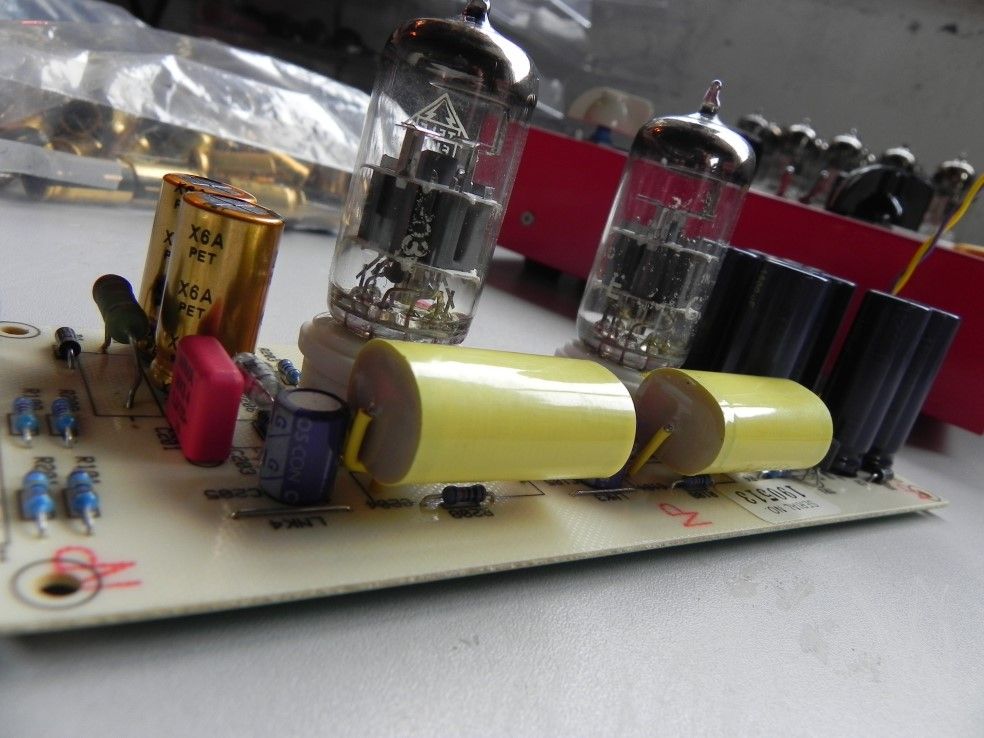 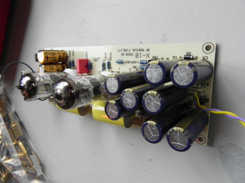 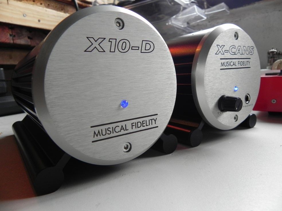 |
|
|
|
Post by PinkFloyd on Apr 16, 2011 21:30:20 GMT
|
|
|
|
Post by PinkFloyd on Jun 12, 2011 20:55:34 GMT
12th June 2011 - Shane Johns X-CAN V2 Really PRISTINE boards on this V2, I don't think the stock unit saw a lot of service, one of the cleanest examples I have seen for a long time: 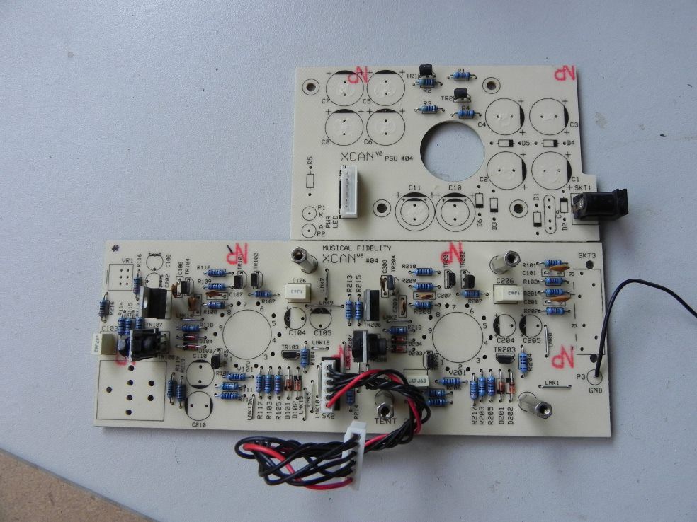 I have fitted the Panasonic FR 1800uF into this one and the rest is pretty much the same as normal with Nichicon MUSE non polar coupling caps (the green ones), UF 4001 ultrafast diodes, Samwha VA series (135C rated) 100uF, WIMA MKS4, Ceramic valve sockets, Purple LED, Jalco pro headphone socket, ALPS potentiometer, new gold plated quad phono socket and a pair of Russian 6N23P-EB (from my personal stock) matched on a Tube Imp analyser. You know, the Tube Imp has been a very good investment and I feel so much better being able to closely "match" a pair of valves rather than just "testing" them to see if they work..... I am happy to report that the large batch of 6N23P-EB I bought are "true" military spec as most of them I have tested, so far, are VERY close to each other with respect to transconductance, gain and current.... I think (so far) I have measured only ONE which was a fair bit out on one side.... fantastic quality and a LOT more consistent than the USA built JAN Philips 6922 which are nowhere near as close in tolerance and a lot more time consuming to physically match a pair. Anyways..... enough yapping.... here's the pRon: 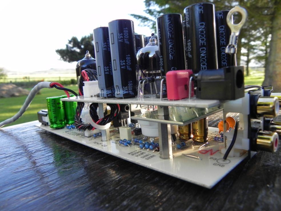  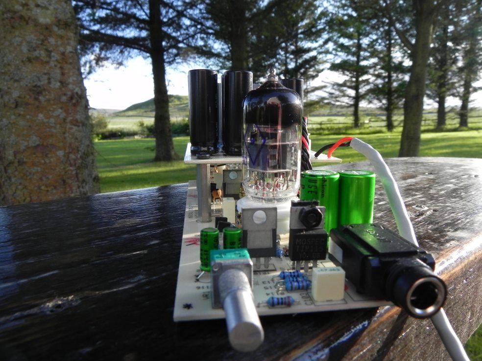 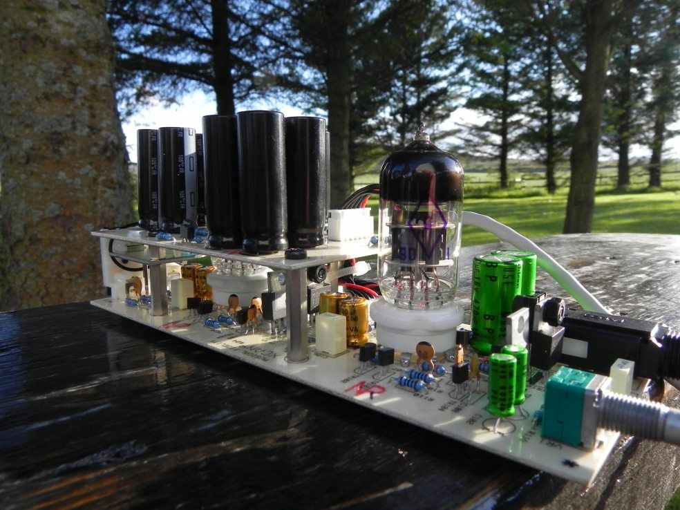 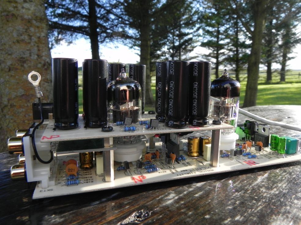 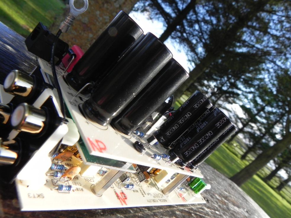 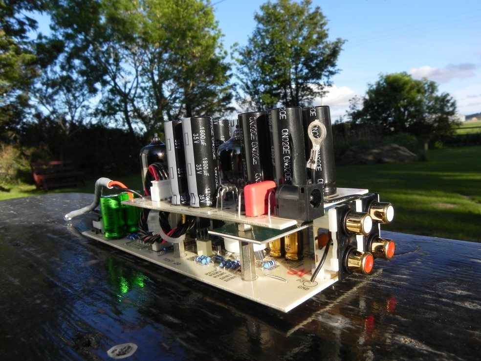  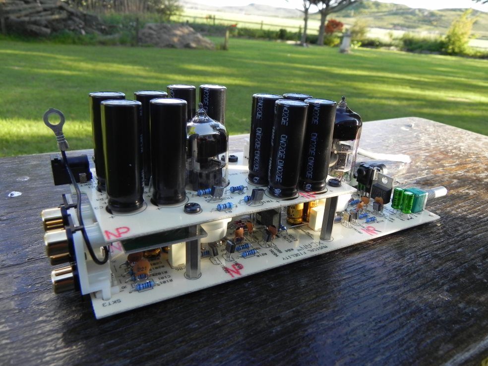 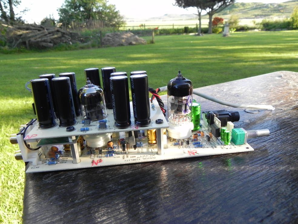 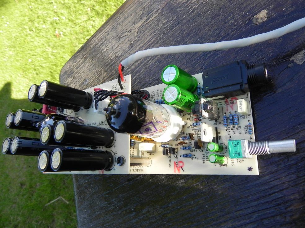 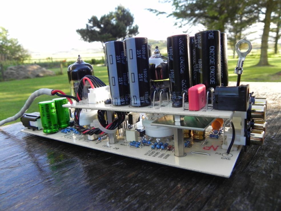 |
|
mrarroyo
Been here a while!  Our man in Miami!
Posts: 1,003
|
Post by mrarroyo on Jun 12, 2011 22:18:38 GMT
Mice work as usual Mike. I see you kept the coupling caps instead of ferrite, I gather the user has some dc out of his source. Right? Yeah, I do not know much so if I am totally off base I will shut up.
|
|
|
|
Post by bertiewooster on Jun 13, 2011 5:55:25 GMT
Wow - apart from the 'guts' and assembly it's just amazing for a non-DIY person like me to see these pics of the strip down and upgrades. It's looking really good, Mike - thank you  Miguel - at the moment I'm using a Matrix Mini-i DAC connected via RCA to a Matrix M-Stage amp with opamp upgrade. The DAC is also now connected to my old Arcam Alpha 7SE cd player (sometimes I play through my MacBook Pro via lossless with iTunes or FLAC with Songbird). |
|
Deleted
Deleted Member
Posts: 0
|
Post by Deleted on Jun 13, 2011 6:15:22 GMT
It's just as well Mike doesn't charge realistic hourly rates !  Mike's meticulous attention to detail never ceases to impress me. Alex |
|
|
|
Post by PinkFloyd on Jun 13, 2011 21:15:59 GMT
It's just as well Mike doesn't charge realistic hourly rates !  Mike's meticulous attention to detail never ceases to impress me. Alex Thanks Alex, that was very nice of you. I do like to take pride in my workmanship and always do it to the best of my ability. I want people to look under the bonnet and say "nice job".... not have a look and say "what a bodge up merchant!".... there are very few trades these days where "perfection" is called for... most of the building sector relies on nail guns and sealant etc. and as long as the outer skin "looks" ok that's good enough for them (even though the foundations may be rotten)... I like doing things properly and it makes my day when somebody says "lovely job". I was taught that way by my Father and even small things like "dressing" screws on a panel show that the guy who has done the job has taken care and has done that job to the best of his ability. As to the "time" thing.... I have perfected my technique (over the years) and can strip and re-populate a V2 (for example) in under an hour.... I have all the tools, the technique and the parts so this part is not at all time consuming. The "time consuming" part is fault finding! You can spend anywhere from 10 minutes to ten days tracing a fault and you have to always allow for this.... fortunately (touchwood) 99% of my work fires up first time but there is sometimes an occasion when it doesn't! The older I get the easier it becomes and this is how it should be.... if I was still making the mistakes I did when I was a 16 year old then my head must be full of sawdust.... with age comes wisdom and experience and you know what to avoid and what to look out for "before" it happens  I am really enjoying working on amps at the moment and have even been working on local musician's guitar amps / pedals etc.... I totally went off all things "audio" a while ago but after taking a few months out I am back enjoying it again.... learning to "control" my time spent on audio (a few hours a day instead of 24/7) and enjoying working on other non audio projects. Mike. |
|
|
|
Post by lark on Jun 14, 2011 12:50:01 GMT
I've got to agree - while I don't have any of Mike's work - from all the images I've seen, it all looks first class.
As someone who always strives to do their best, I have every bit of respect for the effort Mike puts into this work and it deserves every bit of praise it receives here.
If this gear sounds anything like it looks............. I need some!
Lark
|
|
|
|
Post by dicky on Jun 14, 2011 14:19:20 GMT
Mike, I have to ask ... why are some of the diodes on tip-toes? I think I've seen other components mounted 'off' the board elsewhere.  |
|
|
|
Post by PinkFloyd on Jun 14, 2011 20:08:12 GMT
Mike, I have to ask ... why are some of the diodes on tip-toes? I think I've seen other components mounted 'off' the board elsewhere.  Hi Dicky, Where there is heat I like to keep the components away from the PCB... nothing more exotic than that  There is a point (next to the transistors) on the V3 where the three resistors (either side of the transistors) have been raised by MF, they used to fit them all flush to the PCB on early V3's. The reason they raised them is that this section of the board totally fries in a fault condition... it takes out all the transistors and the three resistors I speak of (usually on just one channel).... I have seen "quite a few" V3's that have burnt out and they have ALWAYS gone in the exact same way.... The three resistors (flush mounted to the board) used to turn the board to charcoal making a repair VERY time consuming.... simply raising them off the board protects the PCB, pads and trace should they decided to cook themselves..... A guy recently sent me one that had cooked itself and you can see the damage that three HOT resistors can do to the board!  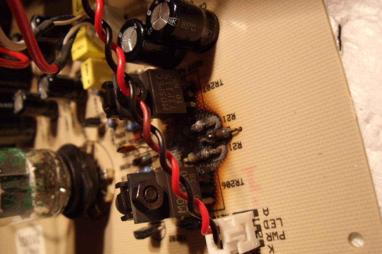 The "fix" is not a pretty sight either!  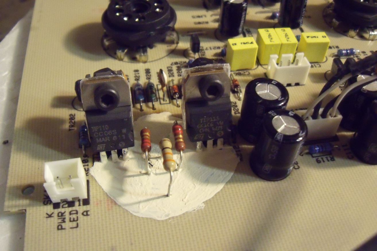 Unfortunately, not long after his amp arrived back the EXACT same thing happened again and my advice to him was to scrap the amp as it just wasn't cost effective to repair. ALL of that damage could have been avoided if the resistors had been mounted high up from the board..... This is a quite a common sight in a V3 and it's still a mystery as to what causes it.... 3 or four of the PSU caps explode, a few diodes are taken out, all the transistors are taken out.... it's just carnage in there! I, personally, reckon it's due to a valve failing and would urge all V3 owners to replace their valves from time to time.... all of the ones I have seen like this have had the stock valves in for YEARS (according to the owners) and they all report the same thing.... a gradual degradation of sound in one channel and then ZILCH! The V2 amps are pretty much bullet proof. |
|
|
|
Post by dicky on Jun 14, 2011 20:30:06 GMT
Thanks for the explanation, Mike.
My V2 gets quite warm and the TIP transistors have scorched the board a bit (it was like it when I bought it). I fitted some heatsinks to them to try and give the board an eaiser time. There's not much room in there so I had to try a few different types before I found some that didn't foul the other components. I don't know how effective the 'mod' is but it can't hurt. I guess, ideally, the can should be ventilated to get the heat build-up out - but I'm to chicken to take a drill to it.
|
|
|
|
Post by PinkFloyd on Jun 14, 2011 21:13:19 GMT
Thanks for the explanation, Mike. My V2 gets quite warm and the TIP transistors have scorched the board a bit (it was like it when I bought it). I fitted some heatsinks to them to try and give the board an eaiser time. There's not much room in there so I had to try a few different types before I found some that didn't foul the other components. I don't know how effective the 'mod' is but it can't hurt. I guess, ideally, the can should be ventilated to get the heat build-up out - but I'm to chicken to take a drill to it. You will generally find that the "scorched board" examples of the V2 have come from owners who have left them on 24/7/365 for over 10 years.... Just look at the example in the last V2 post..... the guy I bought that one from listened to it "twice" a week "tops" and switched it off when it wasn't in use.... if there is browning to the PCB under the transistors it is there because A: there has been prolonged heat and B: the PCB quality is SHITE! So much as wave a soldering iron in the direction of a V2 board and a pad will lift  They are very inferior "fit once" types of boards and are prone to discolouration from warm components. Don't worry though, it is the nature of the beast and the FACT that they are STILL giving good service after 10 years solid use indicates they are more than fit for duty. Transistors DO get hot (they are meant to) and a bit of browning to these PCBs is to be expected.... it is all OK and perfectly normal with this type of PCB. I must update my website as there is no need, at all, to ventilate these enclosures.... the "can" disippates most of the heat and adding heatsinks or drilling holes is just a placebo fix... The V2 is pretty much bullet proof and VERY reliable in service.... instead of drilling holes and adding heatsinks it may be a better idea to supplement the connections if your V2 has been subjected to heavy usage over the years.... adding heatsinks onto the TIP 110 /115 will do very little apart from possibly loosen the pads from the board when you are tightening them on! Turn the board over, arm yourself with a sharp craft knife... scrape away about 5mm of the track (the green surface) to expose the copper underneath..... flood this with solder, that will supplement the joint and you should be good to go for another 10 years. A transistor either works or it doesn't, there is no inbetween, so don't be paranoid and think your transitors are "wearing out"  If you ARE anal and decide to replace the transistors then I can supply you with an entire new set..... Not too expensive, probably about £8 shipped for the COMPLETE set. Same things applies when fitting the new transistors but, this time, scrape back ALL the track to expose copper up to the next component.... form the legs over the tracks, solder and point to point with the next component on the track.... that will last FOREVER  Don't worry Dicky..... a bit of "browning" is absolutely normal, and to be expected after all those years giving 24/7/365 duty.... it does not have a negative impact on anything (apart from eye candy).... Hope this helps. Mike. |
|
|
|
Post by PinkFloyd on Jun 14, 2011 21:25:54 GMT
By the way..... The V3 resistors are "raised" in later editions as can be seen here:  |
|
|
|
Post by dicky on Jun 15, 2011 6:21:07 GMT
Thanks for he tips, Mike, I'm not actually worried about the heat. I only added the 'sinks to help the board out at bit  |
|
|
|
Post by PinkFloyd on Jun 16, 2011 19:52:31 GMT
|
|
joethearachnid
Been here a while!  Old head on young shoulders.
Posts: 380
|
Post by joethearachnid on Jun 16, 2011 20:48:59 GMT
I love the cheeky shot of the warning on the back. What are you supposed to do when your tubes start to go? Send it back to MF so they can harge you a hefty service fee for opening the thing and popping in a pair of tubes?
Then again, I'd say that you're probably a 'qualified engineer' even if you're not endorsed by Musical Fidelity...
-JoetheArachnid
|
|
|
|
Post by PinkFloyd on Jun 16, 2011 22:11:31 GMT
100% certified by the "university of life".... I would not entrust anything to a 19 year old with a "degree"  the only "university" I have experience of is LIFE..... I have honed my skills through trial and error over MANY years..... not sure if I'm "qualified" to undo a few screws but I am out of the "curriculum" when it comes to making amps sound good  Maybe I should start "teaching"?  |
|
joethearachnid
Been here a while!  Old head on young shoulders.
Posts: 380
|
Post by joethearachnid on Jun 16, 2011 22:40:49 GMT
Maybe I should start "teaching"? If you want to teach soldering and electronics I think you're doing a pretty damn good job already! Between you and Prof. Frans I've learned a great deal from just reading on here. -JoetheArachnid |
|
mrarroyo
Been here a while!  Our man in Miami!
Posts: 1,003
|
Post by mrarroyo on Jun 16, 2011 23:46:01 GMT
Mike, is the sound of the V3 closer to the V2 now that you are using a new type/rating of caps/diodes?
|
|
|
|
Post by mrpharmacist on Jun 20, 2011 7:54:54 GMT
Mike, is the sound of the V3 closer to the V2 now that you are using a new type/rating of caps/diodes? Likewise curious!  |
|
|
|
Post by PinkFloyd on Jun 20, 2011 22:41:19 GMT
Mike, is the sound of the V3 closer to the V2 now that you are using a new type/rating of caps/diodes? The V2 and V3 both have different sonic signatures and will NEVER be close..... The V2 is an intimate "small club" type listen... the V3 is a larger venue type listen. All that my mods do is bring the absolute best out of each "venue".... I have no intention of turning a small club into an arena and vice versa..... |
|
|
|
Post by PinkFloyd on Jun 22, 2011 21:02:58 GMT
22nd June 2011 - Elton Stoneman's V-CAN Headphone Amplifier. Elton was experiencing an intermittent loss of one channel when turning the potentiometer, which is quite a common problem with these amps. What causes it is the fact that Musical Fidelity don't secure the potentiometer with a nut so, effectively, every time you turn that knob the potentiometer housing moves resulting in eventual breaking of the pads. This was the case with Elton's amp.... three pads had lifted from the PCB so I desoldered the pot, scraped back all the pot tracks to clean copper... replaced the pot, bent the legs over onto the exposed copper tracks and flooded with solder.... that pot isn't going anywhere! I also fitted a "nut" onto the pot to ensure there is ZERO movement. Pretty poor show from MF not fitting a nut but I suppose they have to make money from these amps by building in obsolescence and would probably charge their standard £75 "inspection" fee to replace the pot  Anyhoo..... this is a weak point and easily fixed with a "nut".... the standard plastic knob will clear the nut so no problems there! I sell these nuts and they are £53.99 (inc. VAT)..... no, seriously.... if any V-CAN owner wants one I will ship a nut free of charge, just pay the postage  A pic of this famous "nut" in situ:  And... from another angle..... 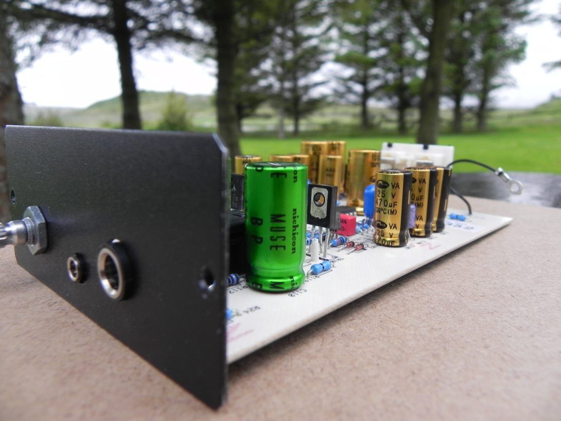 Nuts whole hazelnuts! That's what I call a "nut"  Q: Will this nut make my amp sound better? A: No, it's a nut. Ok ok..... enough about "nuts"  I also fitted my X-CAP and opamp upgrades to Elton's amp and it is sounding fantastic! I fitted my usual Samwha VA (135C rated), OSCON and Nichicon MUSE (in / out) coupling caps as well as adjusting the gain to give a bit more useful travel to the pot.... removed the reverse polarity protection diode and replaced with an axial ferrite link..... all good stuff  I went straight in with an OPA4227 (mounted direct to the board instead of socketing it in a DIP14 turned pin socket) as I feel this is the best chip for Elton's requirements.... direct soldering to the board is the best thing you can do with a chip unless you are a rabid "roller".... in which case you will require a turned pin socket  Just to show you how a big company like MF can rape you with a £75 "inspection fee" and charge £75 for replacing a "resistor" or a "pot"....... I FULLY modded Elton's amp, (X-CAPS and OPAMP) repaired the broken joints on the pot and it cost him £85 for the LOT (no wonder I'm not driving about in a fancy car!).... I really MUST stress this in this post.... I am going to have to DRASTICALLY increase my rates if I am to continue to offer this personal service... when you consider the "time" factor I am actually LOSING money on every amp I mod.... not so much as "losing" it, maybe, but certainly not making any  I am not complaining, just saying that if I am to continue this type of service it MUST be a viable proposition... I can't go on offering a bespoke service for peanuts. Right, I have said my piece..... onwards to the under the hood pRon!....... before the pRon is revealed, however, I would like to show you recycling at it's best  The stock V-CAN "knob" is a shitty piece of "landfill" plastic. I recently said "bye bye" to a 1971 vintage Pioneer receiver (which served me well) and stripped everything out of it.... all that went in the bin was the chassis, the rest I poached for "spares"..... I am happy to report that a 40 year old SOLID aluminium knob has made it's way onto Elton's amp and has been spared from being buried under a pile of earth.... It's little things like this that make me happy (call me a sad bastard) but I am so chuffed that the 40 year old knob is STILL fit for duty and better looking than the crappy "el plastico" (excuse for a knob) that came with the V-CAN..... Elton, every time you turn that knob remember that is is over 40 years old and has a story to tell  OK.... enough of my waffling! Here are the under the hood pics: Whoops..... before I show the pics I forgot to mention that I fitted chromed hex bolts onto the front panel.... thought they looked a bit better than the screws  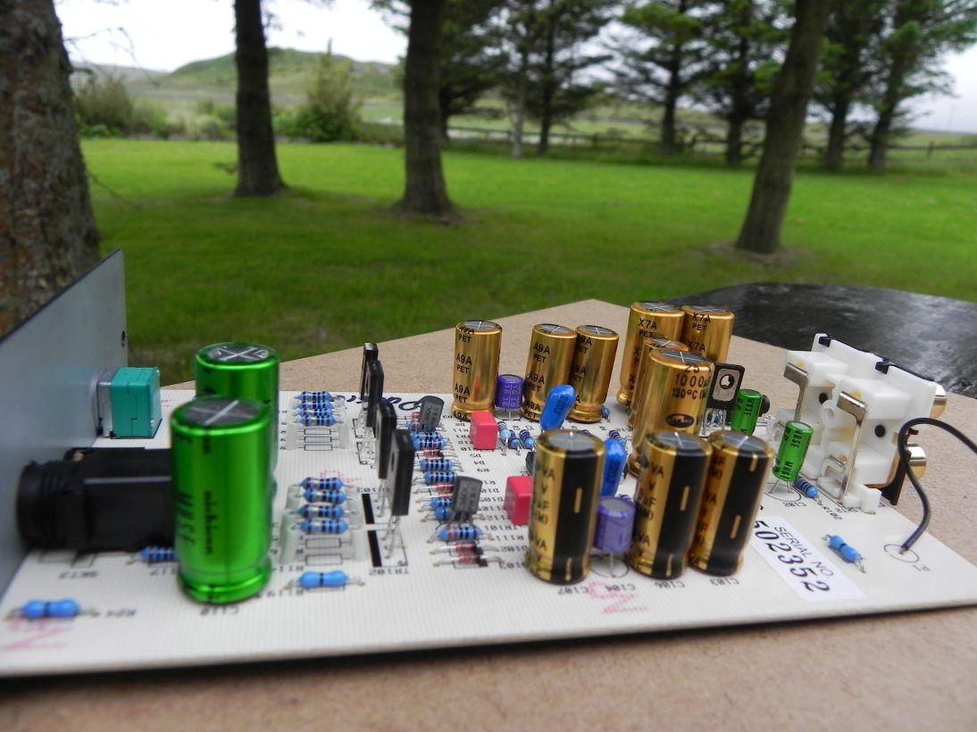 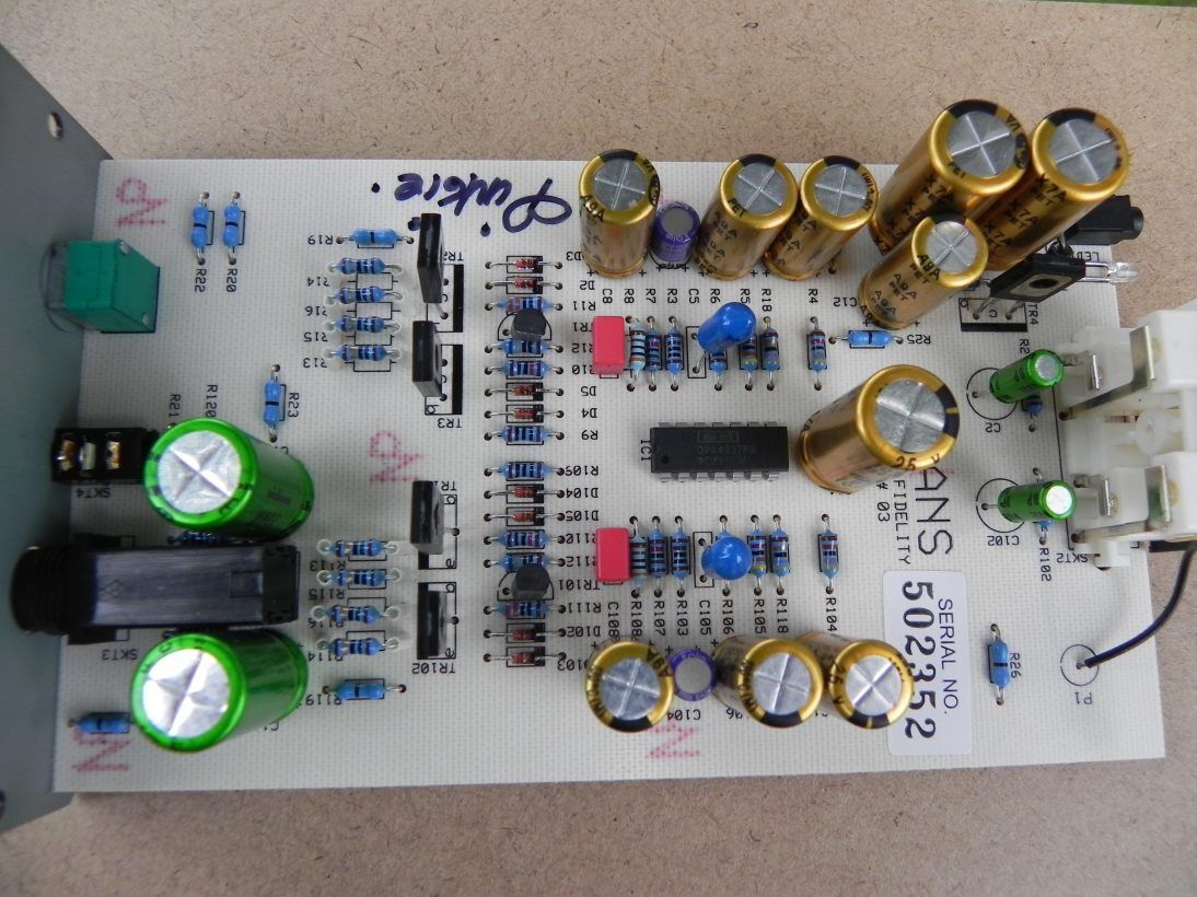 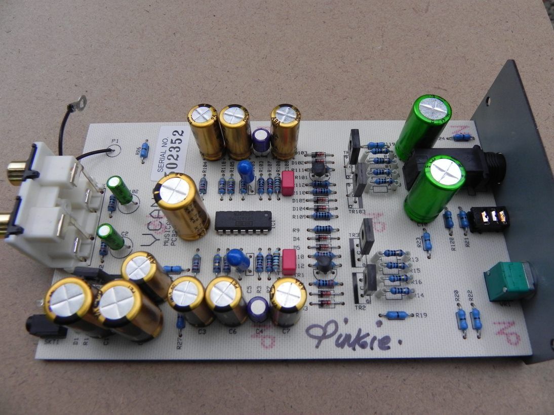 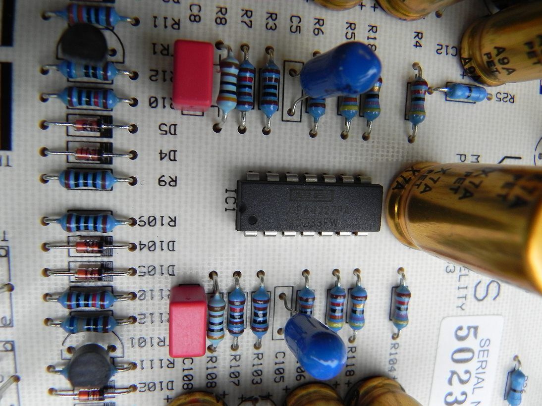 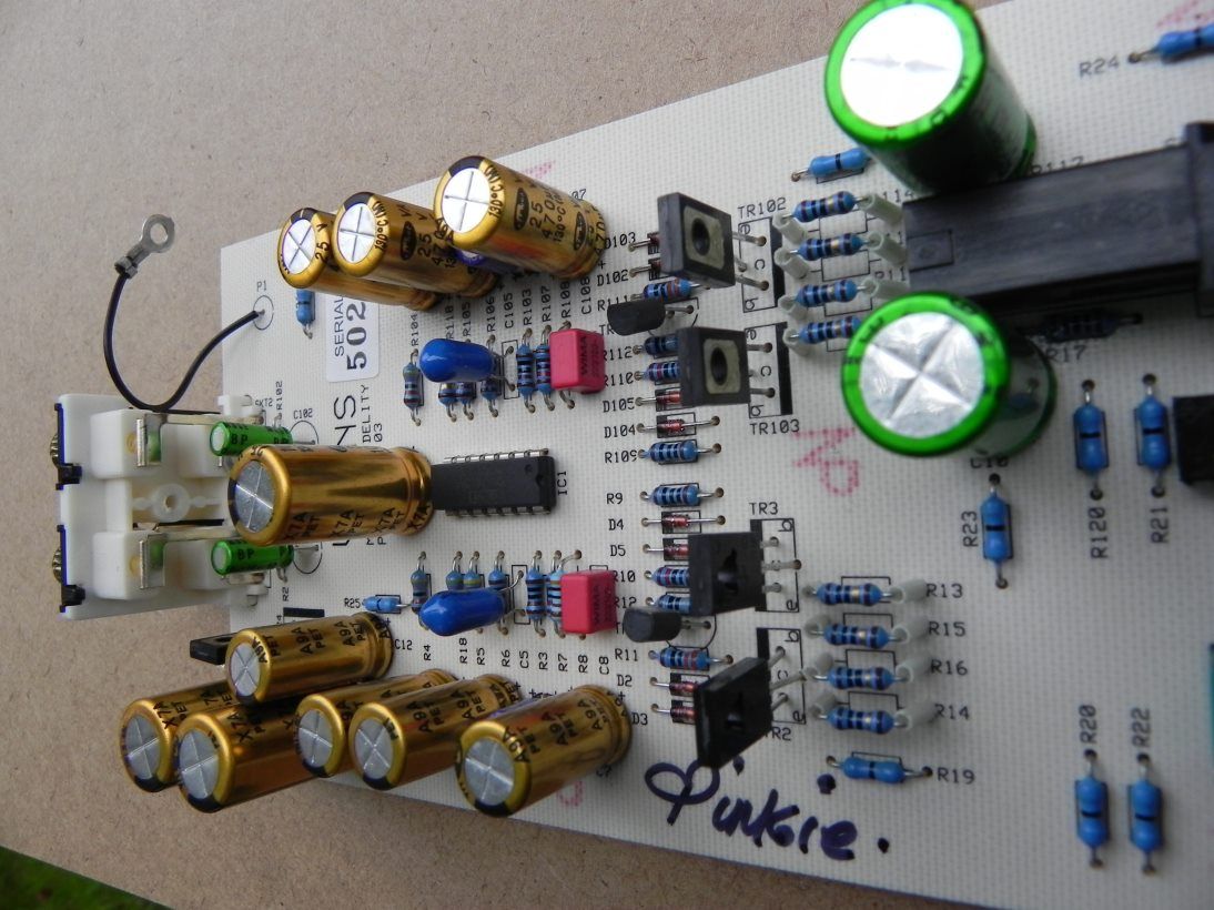 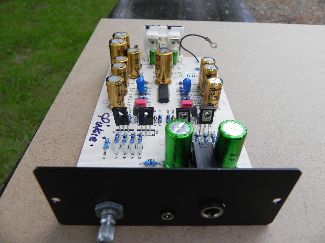 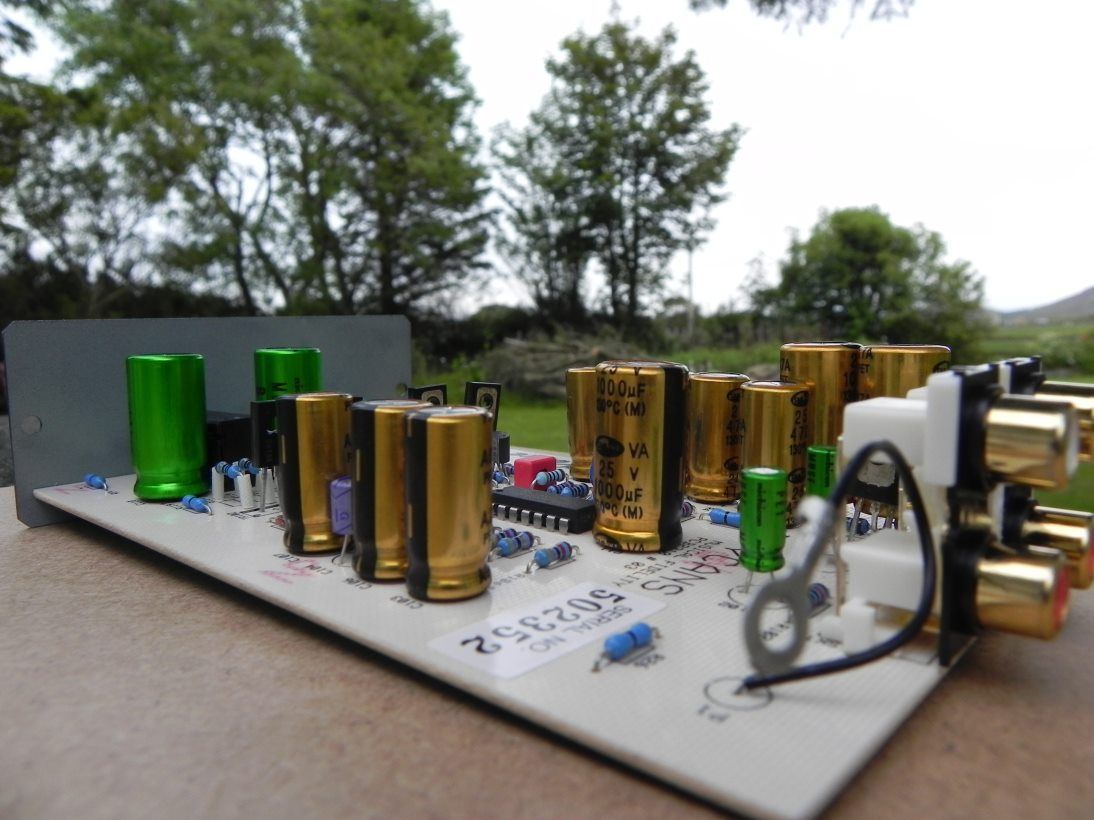 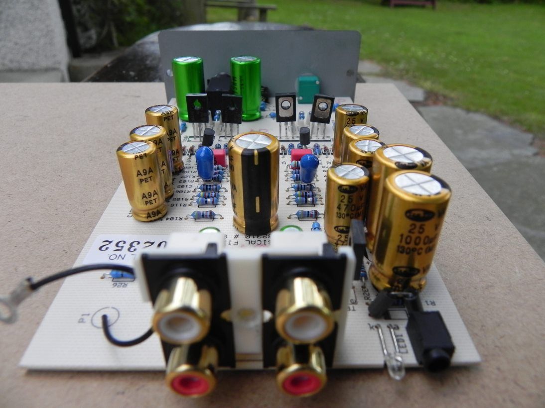   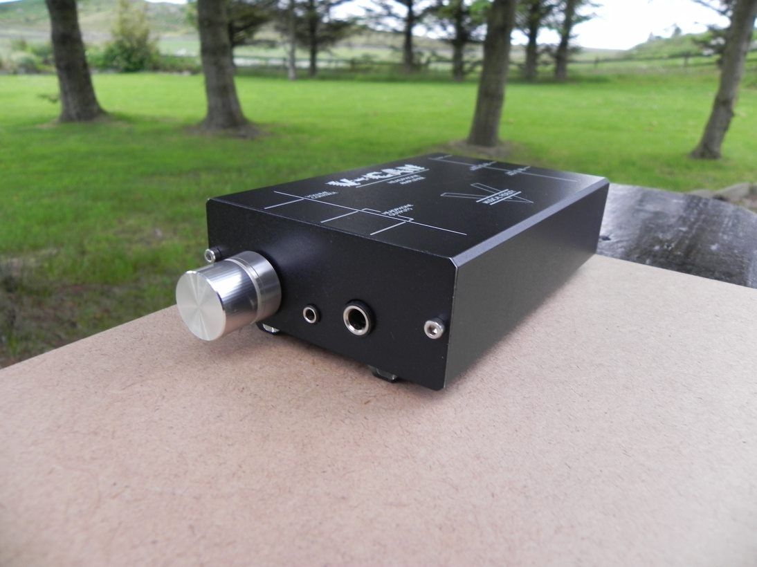  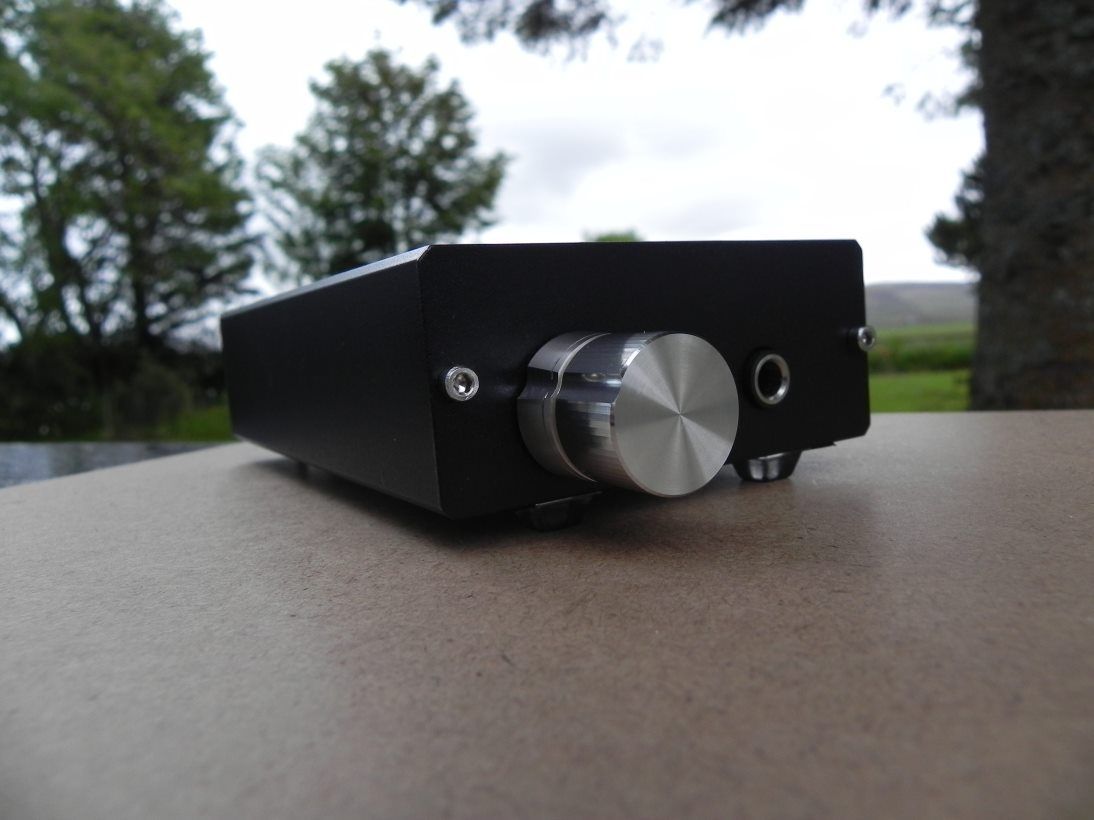 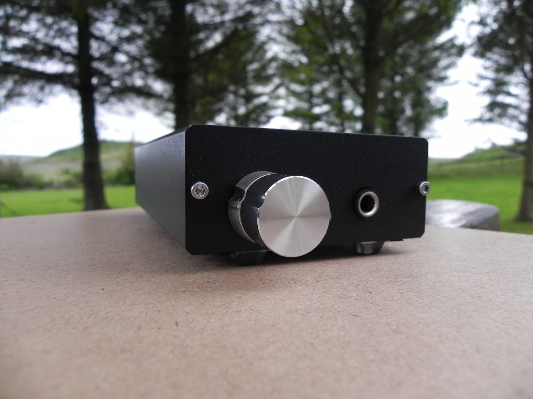 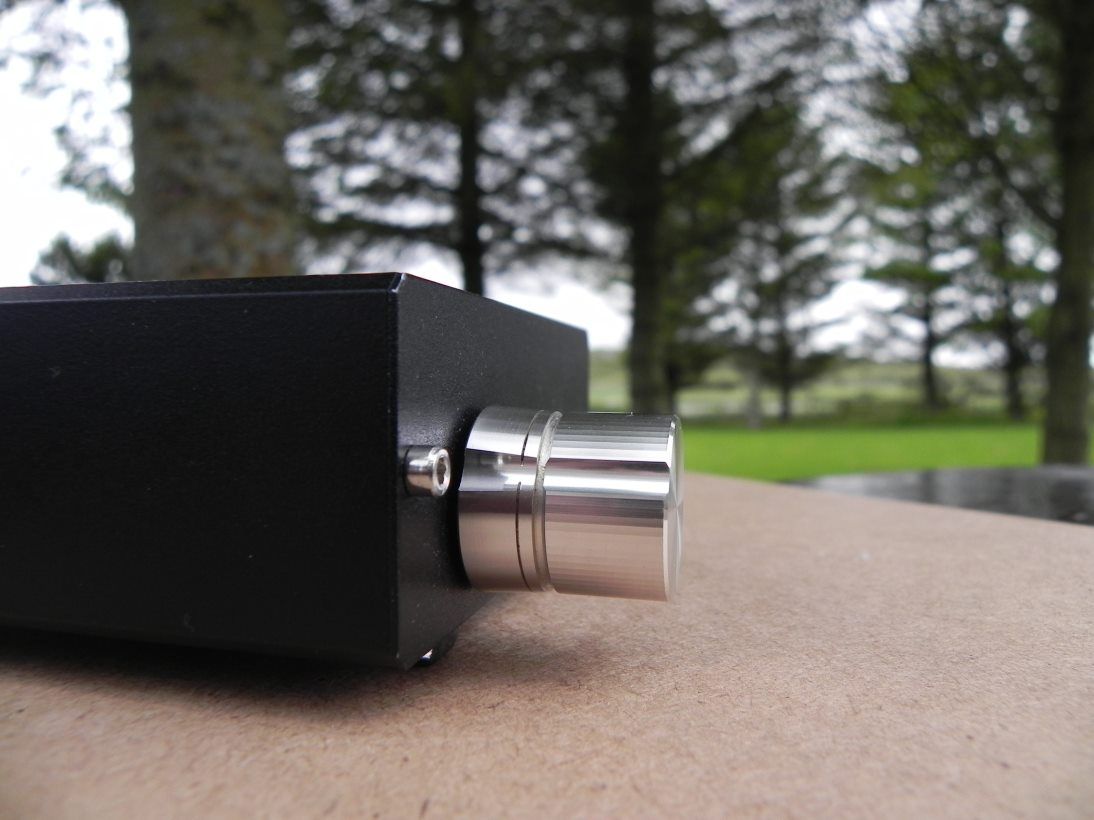 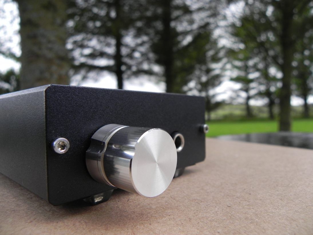 |
|
|
|
Post by PinkFloyd on Jun 22, 2011 21:50:58 GMT
Almost forgot.... I also jacked her up a bit with some 3M "bumpon" transluscent feet so there is more "clearance" to pump up the volume  |
|
|
|
Post by lloydland on Jun 24, 2011 18:15:49 GMT
|
|