thegreatroberto
100+
The Great Roberto "himself" The real deal on a stick!
Posts: 157
|
Post by thegreatroberto on Feb 21, 2006 20:48:23 GMT
So it finally arrived last week. I sold my V1 on ebay and bought a cheaper V2............ On first listening it sounded good; better than the modded V1 yes,well I think yes. Having pulled it apart, I find a pair of our Russian friends in there.........I sold my old V1 with the original Jan/Phillips,reserving the Russians for my V2.So now I have a spare set!  I can't wait for RS to sort themselves out with the FM caps. I reckon I can get some 3300uF FC's in the PSU.....It's going to be a squeeze,but I think it should go ! The new Alps pot is in, but changing that Red LED was a right bitch.It would not come out.Someone had superglued it in.Anyway 5 mins with Dr Dremmel and the old red one was history.(usually they either fall out or require a light tap with a small hammer. I don't think this V2 runs as hot as the old V1, but those TIP110/115 trannies kick out some heat.The board is well scorched arround them.There's not much room to get heatsinks on them either.I may try some 20mm ali screws ? Oh, one observation,the caps on the top board were not Jamicons.Another brand I've seen in my X-Plora.(still shite I expect) And the 2 16V ones were 105 degree rated (they are next to the tube).Those 2 have already been replaced with a pair of 2200uF FC's..... |
|
|
|
Post by PinkFloyd on Feb 22, 2006 14:22:37 GMT
Yes. It does, yes! Awesome! I wouldn't risk 3300uF, they'll be too big (physically) and the inrush current could take out the diodes... 2200uF is the highest I'd recommend in a V2 to be honest and, even then, you'd be lucky to be able to squeeze in 10 of them. The secret in removing the led is to put a piece of cardboard on the workbench. Lay the front panel face side down and push down with all your weight onto it.. the LED will pop out no problems (well you may need to whack the panel a bit) "drilling" it out should be the last resort. You will get heatsinks on the two that require heatsinks, namely the two located under the PSU board, you will have to saw the fins off one side of the sinks so they don't "touch" each other... if they touch you'll get a very big "bang" so make sure there is a gap between them. The best heatsinks for this application are from RS components, Part number: 507-4753 36p each. Perfect size but, as mentioned, you'll have to cut the fins off one of them in order that they don't both make contact. The scorching is Perfectly Normal and you'll also find, if you turn the board over, there's the likelihood the tranny pads have lifted off the board due to the heat...... easy to reinforce just scrape back the green from the tracks to expose the copper and then solder on the copper which will reinforce the transistor connections, it's worth doing this "anyway" as the solder will help dissipate the heat from the transistors. Please see my tutorial on cooling them: Here is what I was saying about leaving them on 24/7/365. I've just finished "cooling" this unit which has been left powered up for the past 4 years. These babies run warm (especially if you live in a warm climate) and the points to watch for are the transistors scorching the PCB and the caps drying out. This doesn't happen overnight but you can imagine what heat the components are subjected to if the unit is left on for years. This is oh so common: 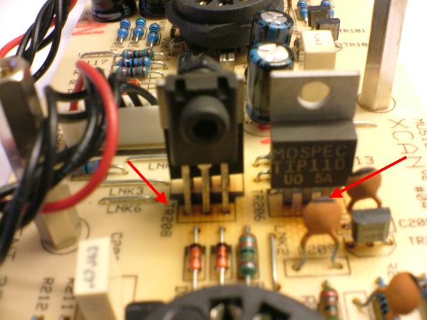 The heat cannot rise upward as the PCB for the PSU is placed directly above the transistors so the solution to help dissipate all of that heat build up is as follows: 1: Drill holes in the PSU board. This will allow the heat to transfer up and away from the transistors (make sure you don't drill through any of the tracks, there is plenty of free board to drill but be careful!): 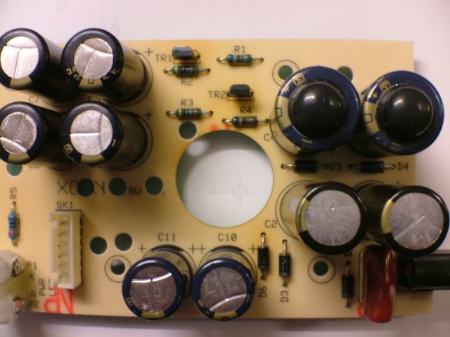 2: Fit suitable heatsinks onto the transistors: 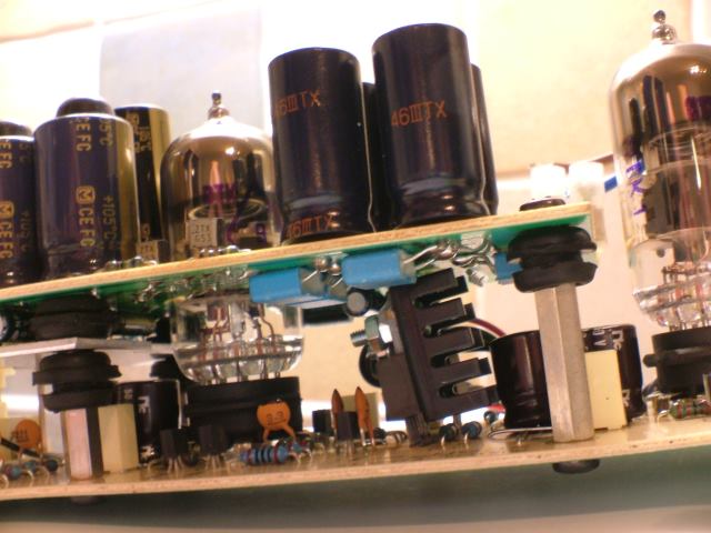 3: If you're a paranoid android then you can also vent the enclosure itself: 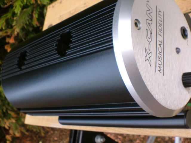 4: Replace all of the 85C caps with high temperature 105C types: 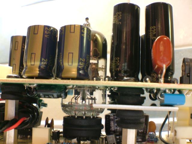 5: Of course it has to look cool too so fit a purple LED and some heat sleeving: 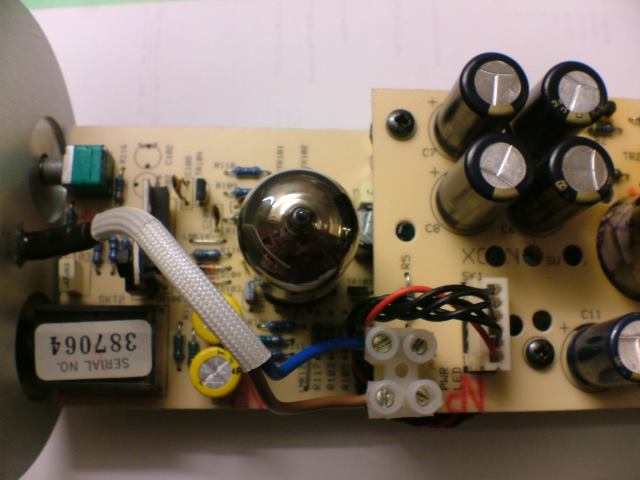 6: To compliment the nice new LED replace the pot and fit a new knob: 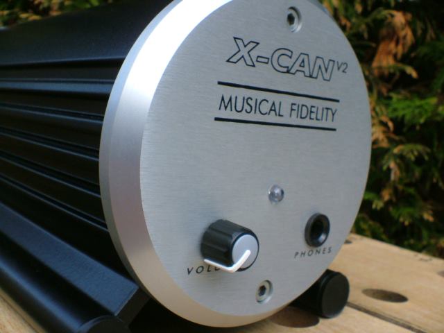 Voila! Runs cool and good for another 10 years :cool: 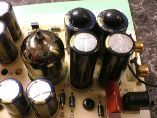 Remember to add those 6H23N-EB long life valves! |
|
Stormy
100+
Advocates putting smokers in a "Sin Bin"
Needs to learn to keep his big mouth shut.
Posts: 153
|
Post by Stormy on Feb 22, 2006 16:31:52 GMT
Mike, is there any risk of the output transistors on the V3 going "bang" if their heatsinks touch? I'm worrying now, as the 'sinks I've used are quite wide and I remember there being very little gap between them...
|
|
thegreatroberto
100+
The Great Roberto "himself" The real deal on a stick!
Posts: 157
|
Post by thegreatroberto on Feb 22, 2006 19:20:30 GMT
The red LED was certainly a difficult one.They normally respond to a gentle tap will a mallet,but not that one.Even with the center gone,no amount of tapping was going to shift it.It needed the dremel all the way.
Yeah,I noticed that the single tranny under the psu was somewhat wobbly.The heat had lifted the track.I'll need to scrape back and solder to a good bit of track.
Any idea what that small steel plate is between the 2 circuit boards ? Or is that another V2 enhancement ?
Heat sinks are my next tweak.I think I'll stop short of venting the casing though.I'm still surprised that it runs cooler than the V1 though.Any ideas ?
Getting those 3300uF caps will not be easy ! The 2 16V caps on the top board have been changed for a pair of 2200uF FC's I had.But being only 16V rated they are a smaller dia.The 3300uF ,35V FC's are dia 16mm X 30mm high.The caps I put in the V1 were 16mm dia,but I think were only 20-25mm high.Anyway I'll see when I get them !
I'm a bit more concerned about blowing the diodes with a large inrush of current.I'll either have to leave it on, or switch it on slowly !!
BTW any idea on the spec of those diodes in case I roast them ?
I didn't quite get the bit about not allowing the heat sinks to touch.Are the sinks on the pair of trannies that are bolted together or on the single tip110 (or on all 3)
Thanks
|
|
|
|
Post by PinkFloyd on Feb 22, 2006 22:49:27 GMT
VERY common in V2's that are more than a few years old. The pads detach from the PCB and the transistors "wobble" No big deal, just scrape the green track coating gently until you expose the copper trace and then fire some solder onto it, this will connect with the solder on the pads and will provide a good as new firm joint, I'll try and get some pictures up to illustrate this. A wild guess.... reduces / shields RFI... but that's only a guess. Some run hot, some run warm, some run cool... depends on ambient temperature, location of unit etc. V2 should be lukewarm to the touch. 1N4007 1amp www.rapidelectronics.co.uk/rkmain.asp?PAGEID=80010&CTL_CAT_CODE=&STK_PROD_CODE=M33890&XPAGENO=1You'd soon "get it" if you connected two of the transistor collectors together. If you're fitting heatsinks make sure the sink is seperated from the collector by means of a silpad and plastic mounting grommet so the heatsink is, in effect, entirely insulated from the transistor... this is not "essential" unless there's the possibility that that one heatsink could contact the other in which case collector would be connected to collector and you really "don't" want that. The other way to do it is to fit the heatsinks without insulation and supplement the nut and bolt fixing with a small bead of heat resistant epoxy so in the unlikely event the fixing comes loose the epoxy will hold the heatsink in place ensuring it doesn't fall over and touch the one next to it. Stick a screwdriver blade between the two collectors and you'll see what I mean (DON'T!!) Thermal insulating pads and mica bush: 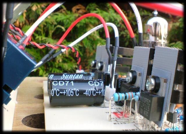 |
|
Stormy
100+
Advocates putting smokers in a "Sin Bin"
Needs to learn to keep his big mouth shut.
Posts: 153
|
Post by Stormy on Feb 23, 2006 12:30:35 GMT
Do the mica bushes extend into the hole in the casings of the transistors to stop the screw from creating an electrical path between the casing and the heatsink, or is that left to chance? If the bushings are any more than a "washer", where did you get them from?
I've just noticed that your 33ohm resistor in the photo above looks bigger than the 10s that surround it - did you up their power rating like me?
|
|
|
|
Post by PinkFloyd on Feb 23, 2006 14:06:36 GMT
|
|
thegreatroberto
100+
The Great Roberto "himself" The real deal on a stick!
Posts: 157
|
Post by thegreatroberto on Feb 23, 2006 18:37:10 GMT
Thanks,completely missed the bit about the collectors of the trannies being at different PD's ! Doh !
I was thinking more about the heat sinks touching the underside of the PSU board.
Now got 8 of my 3300uf,35V caps on the psu board.And yes they are big.....It was a tight fit.The 2 16 V caps were already replaced (by me) with 25V 2200uF FM's...............And yes, the lights did dip when I switched her on.No obvious changed yest, but I hope the next week or so brings a few positive changes !
Sorted my 2 wobbly TIP 110's Like you said,a scrape and extra solder.I wonder how many V2's die due to these trannies getting loose and then breaking the track ?
I wonder why the TIP115 and the SC tranny are "bolted" together ? Is it for mutual support or does it act as a heat sink ?
|
|