|
|
Post by musicmanic on Feb 26, 2021 21:41:50 GMT
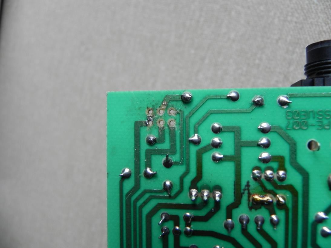
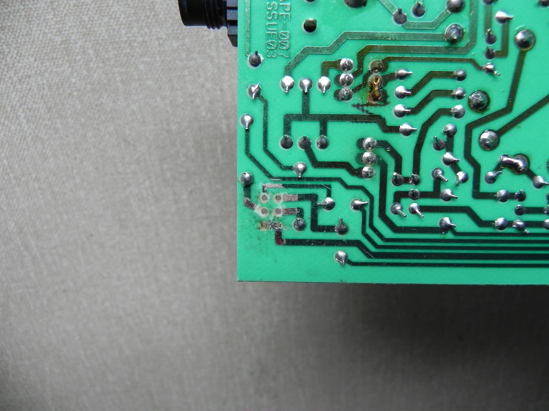
 My pot recently only let sound out of the right ear only and I had to push it a certain way for sound to appear in the left ear too. Mike told me it was the solder joints. I've tried it a few times but I guess the solder joints aren't correct. I have uploaded some pics for advice. Does the joint at the bottom have to be fused or are they all just single solder joinmts?: Pic 1Pic 2P.S. Is there a way I can test if the pot is faulty? |
|
|
|
Post by PinkFloyd on Feb 27, 2021 10:10:21 GMT
You've lifted all the solder pads off of the PCB?
|
|
|
|
Post by musicmanic on Feb 27, 2021 14:45:36 GMT
You've lifted all the solder pads off of the PCB? Ah, they must have come off with the desoldering. I guess some must’ve been loose. That’s why the sound would only come through when I pressed down. I’ll send it up to you Mike if I can. |
|
|
|
Post by PinkFloyd on Feb 27, 2021 19:40:09 GMT
You've lifted all the solder pads off of the PCB? Ah, they must have come off with the desoldering. I guess some must’ve been loose. That’s why the sound would only come through when I pressed down. I’ll send it up to you Mike if I can. e-mail sent James..... no probs at all...... I will post photos of the fix (how to solder direct to the tracks) using your V2 as the reference point (Not a Guinea pig experiment / I know what I'm doing / I think  ) Yes, a couple of the solder pads may have had hairline cracks between the pad and track...... the pot is not "physically" secured to the front panel with a nut so (over time) continual movement "can" cause a hairline fracture between the solder pad and the track resulting in intermittent channel drop out and (eventually) permanent channel dropout. Anyhoo.... send the boards to me and I'll have that 100% good for you in no time mate. All the best, Mike. |
|
|
|
Post by PinkFloyd on Mar 3, 2021 20:35:12 GMT
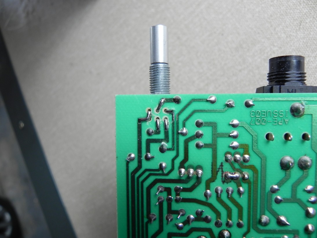
OK, All good  Here is the fix: You had lifted all six of the solder pads James meaning there was no mechanical "join" between the pot and the rest of the circuit as you can see here:  The first thing to do is to gently scrape back the green track coating layer to expose the copper track...... this is best done with a craft knife with a chisseled blade:  You then bend over the pins of the potentiometer, flush to the board, making sure they align correctly onto the exposed sections of copper track...... sounds easy.... doesn't look pretty BUT it's the way to do the job:  Now for the icing on the cake! Flood in a suitable amount of solder and that pot is a lot more secure than it ever was   The pot now has a better footprint and is good to go forever and a day  As I say, it doesn't look pretty but neither does open heart surgery......... Your amp is 101% good to go and the direct to track fix is far superior to the original flimsy solder pads........ I tested your original pot and it is 100% good in every respect, I will send it back with your amp. Your valves tested VERY good so no need to change them, they are spot on. I replaced the blue LED (that had broken off) with a new one and also fitted a 100K glow taming resistor to R5...... the LED that was in there could have been used for laser eye surgery! Thank god it had broken off, I dread to think what the stock 330R resistor plus ultra bright blue LED would have done to my eyesight..... jesus it must have been like staring into a laser? Anyhoo..... all is good....... amp is 101% firing on all four. All the best, Mike. |
|
|
|
Post by musicmanic on Mar 3, 2021 21:14:24 GMT
Excellent job Mike and thanks. I noticed the two pins on the left are fused together? Could you explain what each pin does with the circuit? It looks solid now and I look forward to listening through it again.
Thanks
|
|
|
|
Post by PinkFloyd on Mar 3, 2021 21:39:55 GMT
Excellent job Mike and thanks. I noticed the two pins on the left are fused together? Could you explain what each pin does with the circuit? It looks solid now and I look forward to listening through it again. Thanks The two "fused together" go to ground. perfect. |
|
|
|
Post by musicmanic on Mar 3, 2021 22:08:41 GMT
Excellent job Mike and thanks. I noticed the two pins on the left are fused together? Could you explain what each pin does with the circuit? It looks solid now and I look forward to listening through it again. Thanks The two "fused together" go to ground. perfect. Ah I bet it's as quiet as anything now. |
|