|
|
Post by themystical on Dec 11, 2012 15:36:21 GMT
Sorry, have you tested the Amanero just by using USB 5V power just by plugging it into the PC after installing the Amanero driver? PC should recognise it straight away and install the correct USB driver. No fancy super power yet. Test recognition by PC first. I have not read the whole thread so I'm not sure whether you have tested PC recognition first. Btw, you should be measuring impedance and not resistance. So your static measurment at 1.1 ohms means nothing in the dynamic work. Thanks for your help. Yes sorry I should have explained that it was all working fine in my "temporary" installation and then I decided to install it "permanently" in my DAC in a fairly complicated install which includes an Arduino with LCD Display and remote control including I2C connections from the Amanero Board. Something went wrong during this process and further investigation has revealed that Pin 12 (SDA) is now shorted to both the 3.3V bus and ground. This seems to be happening within the Xilinx chip.....so basically I seem to have destroyed my board!  Not to worry, I have ordered another one from Domineco. |
|
XTRProf
Fully Modded
Pssst ! Got any spare capacitors ?
Posts: 5,689
|
Post by XTRProf on Dec 12, 2012 6:31:04 GMT
Thanks for your help. Yes sorry I should have explained that it was all working fine in my "temporary" installation and then I decided to install it "permanently" in my DAC in a fairly complicated install which includes an Arduino with LCD Display and remote control including I2C connections from the Amanero Board. Something went wrong during this process and further investigation has revealed that Pin 12 (SDA) is now shorted to both the 3.3V bus and ground. This seems to be happening within the Xilinx chip.....so basically I seem to have destroyed my board! Not to worry, I have ordered another one from Domineco. Oh dear, too bad. Pay to learn.  Waiting time too from Amanero. Hope you have a problem free setup after. |
|
pagan
Been here a while! 
Posts: 512
|
Post by pagan on Dec 12, 2012 7:10:00 GMT
Hi Guys I installed the board into my DAC and upon powering it up was having a problem in it not being recognised by Windows. Upon investigation, the 3.3V pin on the board was measuring 0.2V. Clearly something was not right with the power supplies on the board so I decided to remove the U2 regulator suspecting this had blown ( and wanting to power the board at 3.3V at some stage anyway). I now measure 1.1 Ohms between the 3.3V terminal and Ground which doesn't seem right either as by simple Ohms Law, this means it would draw around 3A? Can somebody who has a correctly functioning board measure the Ohmic resistance between the 3.3V terminal and Ground to see what this is and whether I still have power supply problems with my board? I can't just power it up as I have yet to build the 3.3V supply. Recommendations on the format/type to use are also welcome. Regards Avinash With that low resistance, It might be a solder bridged somewhere near the 3.3v line to ground. Also where are you measuring for resistance to ground? The chip might still be ok, just one of the other components not. Which could mean repairable. Allan |
|
|
|
Post by themystical on Dec 12, 2012 11:17:38 GMT
With that low resistance, It might be a solder bridged somewhere near the 3.3v line to ground. Also where are you measuring for resistance to ground? The chip might still be ok, just one of the other components not. Which could mean repairable. Allan Hi Allan I have double checked for solder bridges several times and have definitely pinned the fault down to the Xilinx or Atmel chip I2C connection. I tried lifting the pin on the Xilinx chip to confirm but this is difficult to do. I can't imagine how other people on this forum manage to snip these micro legs off with a side cutter. I can't even seem to get my side cutter tip on to the leg! Domenico has been very good and is sending me the two chips FOC so I need to research a way of replacing them as I haven't got a hot air desoldering station or any other SMD tools. I probably need to "phone a friend" who has these tools if I can track one down...... |
|
|
|
Post by gommer on Dec 12, 2012 11:53:28 GMT
Lifting a pin is most easily done with a surgical knife with very pointy tip (e.g. Xcelite), while heating with a good and fine soldering tip. After wards, you'll probably also need good solder wick with flux to remove solder between pad and lifted leg.
|
|
pagan
Been here a while!
Posts: 512
|
Post by pagan on Dec 12, 2012 12:04:46 GMT
With that low resistance, It might be a solder bridged somewhere near the 3.3v line to ground. Also where are you measuring for resistance to ground? The chip might still be ok, just one of the other components not. Which could mean repairable. Allan Hi Allan I have double checked for solder bridges several times and have definitely pinned the fault down to the Xilinx or Atmel chip I2C connection. I tried lifting the pin on the Xilinx chip to confirm but this is difficult to do. I can't imagine how other people on this forum manage to snip these micro legs off with a side cutter. I can't even seem to get my side cutter tip on to the leg! Domenico has been very good and is sending me the two chips FOC so I need to research a way of replacing them as I haven't got a hot air desoldering station or any other SMD tools. I probably need to "phone a friend" who has these tools if I can track one down...... Hi Any idea how the chip/s got damaged? Years ago we used to just cut the legs with a sharp knife (stanley knife) to replace it. We weren't worried about using the chip again so it wasn't a problem for us. But we did work out were the tracks went under the component so not to damage them. Once you have the chip body off, then the legs can be solder sucker/wicked off. Yes, the EE's just out of college use to watch us horrified. Home use I use one of these www.ebay.com/itm/Hand-held-hot-air-gun-hot-air-desoldering-station-SAIKE-8858-SMD-rework-heat-gun-/160921457509?pt=LH_DefaultDomain_0&hash=item2577aa9365But if you know someone who does them quite frequently, ask them. Nothing like experience  |
|
XTRProf
Fully Modded
Pssst ! Got any spare capacitors ?
Posts: 5,689
|
Post by XTRProf on Dec 12, 2012 12:56:16 GMT
For SMDs, unless you have the correct equipments, skill, steady hands and good eyes, you can easily destroy the PCB pads. So better to take it to someone who had done it before, if you have not done them before, and give you a guiding hand.
Anyway, when I was working in a PCBA plant many years ago, we need to be certified (ie passed the training centre soldering skill test) before we were even allowed to be working in the various sections. No exeptions given to the supervisors, technicians and, in fact, anybody working on PCBAs. We needed to have that skill as we needed to repair thousands and thousands of PCBAs that don't pass the various electronic tests. Btw, SMD PCBAs are not meant to be repaired at the "consumer" levels. It's modular replacement and just scrapped away as the qty is not many at that level. Can't do that at a PCBA plant as we are talking of thousands to millions scrap if no rework and diagnostic.
|
|
|
|
Post by themystical on Dec 12, 2012 17:40:55 GMT
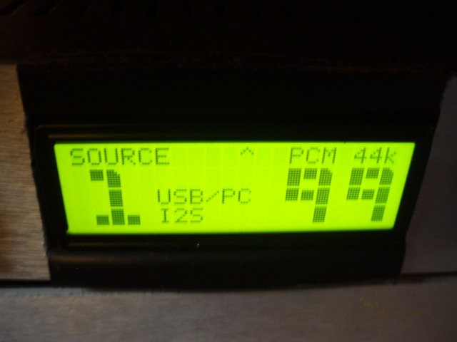
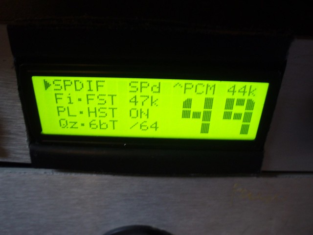
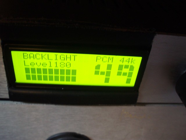
Well I am not completely sure but there were a couple of mishaps during the first switch on. I had got some of the wiring between the Arduino and LCD wrong and there were some shorts which both the Arduino and the LCD coped with. The Amanero board was also connected up at this point, no issues with the connections to the DAC, but I also had the I2C (SDA Pin 12 and SCL Pin 2) connections from the Amanero board to the Arduino. As the Amanero board is not 5V tolerant on the I2C connections, I had the two lines powered via pull-up resistors from the 3.3V supplies on the Arduino and this is where I suspect the line might have ended up getting powered at 5V during the mishaps which may have "welded" the internal contact? Not completely sure. I use the I2C connections to display the frequency and whether it is DSD or PCM on the LCD which is quite a cool feature. You set this up through the configuration tool. I suspect the board is pretty well bombproof - provided you are not using the I2C connections. If you are, I guess you have to be very careful not to exceed the 3.3V. The hot air desoldering station looks very good and very reasonably priced and I suppose SMD is the future so may be a worthwhile investment? |
|
|
|
Post by themystical on Dec 12, 2012 17:47:40 GMT
Lifting a pin is most easily done with a surgical knife with very pointy tip (e.g. Xcelite), while heating with a good and fine soldering tip. After wards, you'll probably also need good solder wick with flux to remove solder between pad and lifted leg. This was the method I was trying using the smallest flat electronic screwdriver (You know the ones that come in a sets of 6 in a small plastic case) I had but got nervous in case I lifted the pad. I might practise on some scraps to get some experience before I have another go. |
|
|
|
Post by themystical on Dec 12, 2012 17:54:37 GMT
For SMDs, unless you have the correct equipments, skill, steady hands and good eyes, you can easily destroy the PCB pads. So better to take it to someone who had done it before, if you have not done them before, and give you a guiding hand At the moment, I would disqualify myself on all four counts that you mention, equipment, skill, steady hands and good eyes.....I posses none of these. But hey this could be a learning opportunity....? |
|
|
|
Post by themystical on Dec 12, 2012 18:01:24 GMT
|
|
Deleted
Deleted Member
Posts: 0
|
Post by Deleted on Dec 12, 2012 22:51:41 GMT
Hi Themystical nice work  what's in the other box's? take care |
|
|
|
Post by themystical on Dec 12, 2012 22:59:47 GMT
|
|
|
|
Post by themystical on Dec 12, 2012 23:08:31 GMT
Hi Themystical nice work what's in the other box's? take care Hi Shaun The middle box is a home made Kondo M77 Preamp clone using a pair of parallel tubes for each channel- the most dynamic and impactful preamp I have ever heard. The bottom box is a DIY 4 Channel Pass B2 Preamp/Buffer. 4 channel because it does my surround sound set-up and allows me to control the volume of all 4 channels simultaneously wired from analogue outs on the Bluray player. This type off set-up sounds miles better than conventional home cinema amps which I gave up on some time ago. Avinash |
|
Deleted
Deleted Member
Posts: 0
|
Post by Deleted on Dec 13, 2012 0:39:13 GMT
Hi Themystical nice work what's in the other box's? take care Hi Shaun The middle box is a home made Kondo M77 Preamp clone using a pair of parallel tubes for each channel- the most dynamic and impactful preamp I have ever heard. The bottom box is a DIY 4 Channel Pass B2 Preamp/Buffer. 4 channel because it does my surround sound set-up and allows me to control the volume of all 4 channels simultaneously wired from analogue outs on the Bluray player. This type off set-up sounds miles better than conventional home cinema amps which I gave up on some time ago. Avinash Hi Thermystical that Kondo San 77 sounds interesting any chance of a link? or some more build details i have a DCB1 buffer knocking around here somewhere which sounds nice. interesting set up you have there.  take care |
|
|
|
Post by themystical on Dec 13, 2012 11:52:05 GMT
Hi Thermystical that Kondo San 77 sounds interesting any chance of a link? or some more build details i have a DCB1 buffer knocking around here somewhere which sounds nice. interesting set up you have there. take care Hi Shaun This is way off topic but there is a guy on a Vietnamese forum who managed to get hold of a genuine Kondo KSL M77, opened it up and took some pictures as well as traced the circuit. It is definitely the real thing, see for yourself on the link below: www.vnav.vn/forum/viewtopic.php?f=46&t=18564&start=0I can't understand a word but there is a circuit further down which is the one that I built but with non of the silver wire, handbuilt capacitors etc. used in the original, just good quality components with a choke power supply. Having tried many configurations of valve pre-amps including grounded grid, aikido etc. and many commercial designs including Quad, Electrocomapaniet etc. this is the best sound I have heard so this has stayed in my system. Best Wishes Avinash |
|
|
|
Post by gommer on Dec 13, 2012 12:15:51 GMT
That blade is a good example. Personally i use this one: be.farnell.com/xcelite/xnb205/blade-pointed-pk5/dp/441016Lifting from the chip side. You put the tip under the pin, then heat and use the knife as a lever. The most difficult part of the job is trying to bend the pin upwards and and not sideways. Cheers, Marc |
|
Deleted
Deleted Member
Posts: 0
|
Post by Deleted on Dec 13, 2012 18:01:00 GMT
Hi Thermystical that Kondo San 77 sounds interesting any chance of a link? or some more build details i have a DCB1 buffer knocking around here somewhere which sounds nice. interesting set up you have there. take care Hi Shaun This is way off topic but there is a guy on a Vietnamese forum who managed to get hold of a genuine Kondo KSL M77, opened it up and took some pictures as well as traced the circuit. It is definitely the real thing, see for yourself on the link below: www.vnav.vn/forum/viewtopic.php?f=46&t=18564&start=0I can't understand a word but there is a circuit further down which is the one that I built but with non of the silver wire, handbuilt capacitors etc. used in the original, just good quality components with a choke power supply. Having tried many configurations of valve pre-amps including grounded grid, aikido etc. and many commercial designs including Quad, Electrocomapaniet etc. this is the best sound I have heard so this has stayed in my system. Best Wishes Avinash Hi Avinash interesting looking circuit and the Nice end of AN  could i be super cheeky and ask how much current is drawn by each channel? i have some Salas HV shunts on order and the Kondo looks like an interesting way of using them (front end only if the currents tooo high). 6n6p (one of my faves) may be a good choice for this and i have bags of them). i used them along with 6n1p front end in my Aikido. sorry for the OT guys. take care |
|
|
|
Post by themystical on Dec 13, 2012 21:32:09 GMT
Hi Avinash interesting looking circuit and the Nice end of AN could i be super cheeky and ask how much current is drawn by each channel? i have some Salas HV shunts on order and the Kondo looks like an interesting way of using them (front end only if the currents tooo high). 6n6p (one of my faves) may be a good choice for this and i have bags of them). i used them along with 6n1p front end in my Aikido. sorry for the OT guys. take care Shaun, I use 12ay7's as per the original Kondo design. Mine measured pretty identical to the measurements shown in the schematic so dropping approx. 140V across a 120k anode resistor - say around 12mA per channel? I am not sure how changing to a 6n6p will effect the operating points, voltages and the currents? I tried ECC82's and 83's but in the end preferred the original 12ay7's. These are all very expensive now so it is well worth experimenting with the 6n6 which is an equally good valve. Avinash |
|
|
|
Post by themystical on Dec 13, 2012 21:35:20 GMT
That blade is a good example. Personally i use this one: be.farnell.com/xcelite/xnb205/blade-pointed-pk5/dp/441016Lifting from the chip side. You put the tip under the pin, then heat and use the knife as a lever. The most difficult part of the job is trying to bend the pin upwards and and not sideways. Cheers, Marc Thanks for the advise Marc. I will see if I can muster up the nerve in due course. Avinash |
|
Deleted
Deleted Member
Posts: 0
|
Post by Deleted on Dec 13, 2012 23:38:57 GMT
Hi Avinash interesting looking circuit and the Nice end of AN could i be super cheeky and ask how much current is drawn by each channel? i have some Salas HV shunts on order and the Kondo looks like an interesting way of using them (front end only if the currents tooo high). 6n6p (one of my faves) may be a good choice for this and i have bags of them). i used them along with 6n1p front end in my Aikido. sorry for the OT guys. take care Shaun, I use 12ay7's as per the original Kondo design. Mine measured pretty identical to the measurements shown in the schematic so dropping approx. 140V across a 120k anode resistor - say around 12mA per channel? I am not sure how changing to a 6n6p will effect the operating points, voltages and the currents? I tried ECC82's and 83's but in the end preferred the original 12ay7's. These are all very expensive now so it is well worth experimenting with the 6n6 which is an equally good valve. Avinash Hi Avinash thanks for the info which is really useful. OK I've ordered up a matched quad of EH12ya7 which where cheap enough to get the ball rolling. i have most of the transformers, chokes and what have you to have a go. but after XMAS now but I'll start a new thread when I'm good to go. now back on topic  take care |
|
|
|
Post by themystical on Dec 14, 2012 11:20:02 GMT
Okay Guys - I am still struggling with this short circuit issue and wonder if you can help me. Let me explain - Please see piccy. I am measuring a short to earth on the 3.3V terminal on the main header. I am measuring a short to earth and also to 3.3V on terminal 12 of the main header - SDA Terminal 12 is connected to Pin 9 of the Xylinx chip (XTDI) and also to 6.8k pull-up resistors to 3.3V track (which I have removed incorrectly suspecting this to be the cause) Pin 9 is connected to Pin 38 of the Atmel chip. This is via track on the underside of the board and rises at a "Via" adjacent Pin 38. The "Via" appears to conflict with a "earth" track that connects to PIn 36 of the Atmel chip and several other components finishing off at Header P3. Can somebody with more experience than me of the construction of multilayer PCB Boards look at the picture and advise whether the Via could physically be short circuited to the track?? Physical because measurements show the Via, Pin 38 and Pin 9 (Xylinx) to be shorted with both earth and 3.3V but this could be because of a short within either of the two chips so the only way of determining whether this is the cause is by sight to see whether there is any physical contact. In my board the Via appears to be in physical contact with the track. As a comparision, I am also posting the excellent piccy that Pagan took of his board and to my eyes, there is "fresh air" between the Via nd the track on his board. I am obviously trying to avoid a situation where I replace the two chips only to find that the problem is actually with the board. Any help very much appreciated. 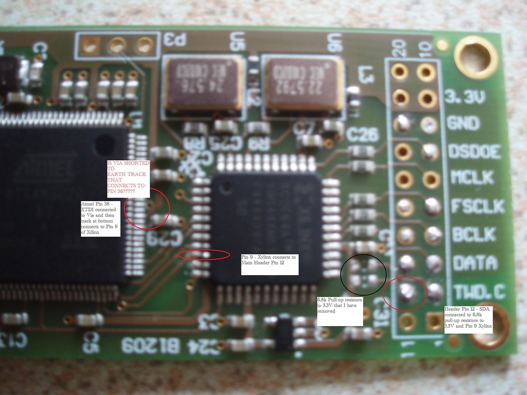 MY AMANERO BOARD MY AMANERO BOARD by themystical2012, on Flickr  Pagan's Amanero Board Pagan's Amanero Board by themystical2012, on Flickr |
|
pagan
Been here a while!
Posts: 512
|
Post by pagan on Dec 14, 2012 12:45:57 GMT
f you can want till tomorrow, I'll take a close up pic of that area. just need the sun to be out. Better still This help?  |
|
|
|
Post by themystical on Dec 14, 2012 14:32:31 GMT
f you can want till tomorrow, I'll take a close up pic of that area. just need the sun to be out. Better still This help? Hi Allan Really appreciate your help. There is no doubt that in your board, there is no physical contact been the Via and the track and that on my board there is overlap between the Via "ring" and the track. What I was unclear about is where exactly the track is vertically within the board and whether it is normally insulated or not. From looking at your detailed picture, it is clear that the track is on top or very nearly on top of the board and therefore in the same vertical plane as the Via "ring". The track seems to be insulated as touching a meter probe to it has no effect. However, I suppose the installation of the Via will probably have taken off the insulation from the track? I am beginning to suspect that this short circuit to ground has always been present on the board, it is only because I have used the I2C connections that it has come into play with the thermal energy from the short circuit "welding" the internal "contact" within the chip to 3.3V? Any views or comments anyone? Avinash |
|
|
|
Post by themystical on Dec 14, 2012 14:39:05 GMT
Forgot to ask Allan, how do you take these excellent pictures? I must have had about 50 attempts, I kid you not, with my cheapie automatic and my best result is no where as clear as yours. Do you use a tripod with quite a long exposure?
|
|


 Waiting time too from Amanero. Hope you have a problem free setup after.