|
|
Post by freddypipsqueek on Apr 13, 2011 14:49:28 GMT
I think I’ve ruined my Styleaudio Carat-Sapphire DAC.  For details of the DAC see - styleaudio.typepad.com/styleaudio_hifi_usb_mini_/2010/05/2010-new-caratsapphire.html. It takes a 6v DC input. I have been using it with a battery. I’ve plugged the battery in the wrong way round. In other words positive to negative etc. The DAC will not now work though there is no evidence of damage on the PCB. Is there likely to be any protection circuit or will I have fried it ??. |
|
|
|
Post by freddypipsqueek on Apr 13, 2011 15:20:20 GMT
Photobucket is down so I can't post any photos
|
|
Deleted
Deleted Member
Posts: 0
|
Post by Deleted on Apr 13, 2011 16:45:05 GMT
That will be hard to tell.
If the DAC had a series diode it would simply not have worked with the polarity reversed but when wired correctly again it would work.
advantage: fool proof
disadvantage: voltage drop (0.4 to 0.6V depending on diode type)
Sometimes there is a reverse protection in the form of a diode in reverse.
This diode will be sacrificed when polarity is reversed.
If they used this topology with a fuse (might be a very small one that doesn't even look like a fuse or even a PCB trace) the fuse might be blown making it not work anymore when polarity is back to normal.
Sometimes manufacturers do not even mount a fuse and if enough current has flown the diode might be fused.
In this case a considerable current will also flow when the polarity is normal again.
Should this diode have gone open circuit in reverse mode the protection would be gone and everything behind it (most parts) will have been destroyed.
the red part near the input connector MAY be a fuse, I cannot tell from the picture.
|
|
jonclancy
Been here a while!  Mr. Ripple Eater
Amateur EAGLEist
Mr. Ripple Eater
Amateur EAGLEist
Posts: 1,131
|
Post by jonclancy on Apr 13, 2011 16:45:13 GMT
It's possible you have popped something. Do you have a schematic? If the 6VDC is regged down to, say 3.3, then there might be a chance you just need to replace a reg or two. You might also find that any polar capacitors might have been damaged and need replacing.
|
|
|
|
Post by freddypipsqueek on Apr 13, 2011 17:32:42 GMT
Thanks for the replies.
Photobucket is due up at 11pm. I will post pictures then. Mine are more detailed and obviously show the 'damaged' state.
|
|
|
|
Post by freddypipsqueek on Apr 13, 2011 17:46:35 GMT
The red part is marked "F101J" and below it, on the PCB, are two "T" shapes with the topes of the "T" facing each other.
|
|
Deleted
Deleted Member
Posts: 0
|
Post by Deleted on Apr 13, 2011 18:32:19 GMT
That's a capacitor, 100pf I think. Those "T" symbols denote the cap. on the board.
Does the book on the unit have any get-out clause like "Only use our specified power supply with this product" or similar?
|
|
|
|
Post by freddypipsqueek on Apr 13, 2011 19:27:24 GMT
I see - Its marked C7 on the board.
I picked it up 2nd hand (fleabay). It didn't come with a full manual. As a lawyer I expect a get out of jail clause.
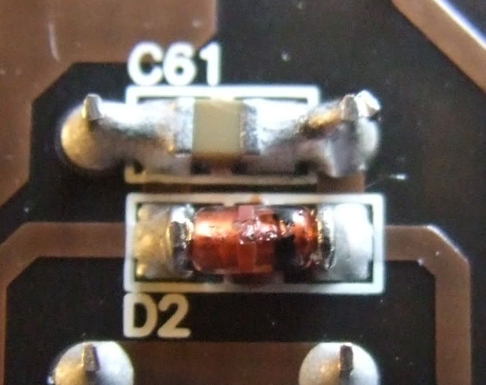
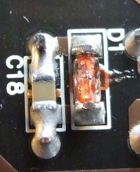
On the bottom side there are 2 items D1 & D2 - They look like surface mounted resisters but are bronze in colour and maybe burnt out - hard to tell with my limited experience.
I will take close ups.
|
|
Deleted
Deleted Member
Posts: 0
|
Post by Deleted on Apr 13, 2011 22:24:15 GMT
It is a mica 100pF cap...
D1 and D2 are diodes.
measure those... if they are 0 Ohm they have been burned out and probably were the sacrificial diodes.
This could mean the DAC is still O.K. if they only shorted (which they are supposed to do) and did NOT go open circuit.
If that happened further damage could be done.
They should be black and have a smooth surface and there might be a white or grey line on one end.
If they look scrorched they probably are.
|
|
|
|
Post by freddypipsqueek on Apr 13, 2011 22:41:02 GMT
Photobucket is still down.
I have determined that D1 & D2 are diodes. They are both surface mounted. They both read a resitance of 179 (DMM set to Diode setting) in both directions. Does this mean they have been shorted and are duff. I cannot tell their value but I could just about fit replacements.
Styleaudio have no customer support so I'm a bit stuffed.
Is it better to give up on this ?.
|
|
Deleted
Deleted Member
Posts: 0
|
Post by Deleted on Apr 13, 2011 22:54:52 GMT
Photobucket is still down. I have determined that D1 & D2 are diodes. They are both surface mounted. They both read a resitance of 179 (DMM set to Diode setting) in both directions. Does this mean they have been shorted and are duff. I cannot tell their value but I could just about fit replacements. Styleaudio have no customer support so I'm a bit stuffed. Is it better to give up on this ?. |
|
|
|
Post by freddypipsqueek on Apr 13, 2011 23:05:31 GMT
Alex.
Thats the kiddy. Thank you for posting the photos.
|
|
Deleted
Deleted Member
Posts: 0
|
Post by Deleted on Apr 13, 2011 23:29:52 GMT
Hi Freddy
I only Googled for photos, and some guy from HeadFi had posted a link to his photos.
Regards
Alex
|
|
Deleted
Deleted Member
Posts: 0
|
Post by Deleted on Apr 14, 2011 6:53:23 GMT
Photobucket is still down. I have determined that D1 & D2 are diodes. They are both surface mounted. They both read a resitance of 179 (DMM set to Diode setting) in both directions. Does this mean they have been shorted and are duff. I cannot tell their value but I could just about fit replacements. Styleaudio have no customer support so I'm a bit stuffed. Is it better to give up on this ?. the inductors (green one near the backplate and 1 bottom side with 101 on it), how do these measure ? (Ohms setting should be close to 0 Ohm) If the diodes are sacrificial ones they should now be 0 Ohm or close to it. You can solder them out ... IF they are sacrificial diodes indeed, and no traces or fuse or other safety parts are open circuit and you have the voltage wired correctly it might do something again. DON'T swap polarity without these diodes present. Connect a battery, switch it on and check the input voltage on the DCDC converter (SPD6-5-1212) +Vin to -Vin. See if there is a voltage there... this should say something about the powersupply. |
|
|
|
Post by freddypipsqueek on Apr 14, 2011 14:14:07 GMT
The green inductor (L6) gives a reading of 26ohms.
On the bottom side there are 3 marked 101. The two under the transformer (SPD6-5-121) give readings of 11ohms.
The one next to the power input gives no reading - i.e. an open circuit.
I'm having a bit more of a look.
|
|
|
|
Post by freddypipsqueek on Apr 14, 2011 14:39:53 GMT
The diodes both measure 179Ohm across both ways.
There are no voltage readings either side of SPD6-5-1212
|
|
Deleted
Deleted Member
Posts: 0
|
Post by Deleted on Apr 14, 2011 15:00:20 GMT
I assume the inductor close to the power plug has gone open circuit (has functioned as a fuse).
What you can do is remove the 2 diodes and remove the open inductor on the bottom.
measure the resistance on the place where the diodes were situated as if they were there.
Should the readings be the same more damaged might have occurred.
Should the readings differ (being higher) you might be lucky.
Now replace the removed inductor with a wire and see what happens when you power it up..
In case it starts working again (a small maybe !) switch it off after checking functionality and repace the parts with similar ones (100uH inductor with about 10 Ohms resistance) and the 2 diodes.
Perhaps a sharp detailed close-up pic of the offending diodes could help.
Unfortunately I am offline for the next couple of hours so can't assist till friday again.
|
|
|
|
Post by freddypipsqueek on Apr 14, 2011 15:51:04 GMT
|
|
Deleted
Deleted Member
Posts: 0
|
Post by Deleted on Apr 14, 2011 16:03:39 GMT
Those are knackered !
Should you be searching for those parts the outline is called 'mini MELF'
It will probably be 1N4148
The black rings (what's left of it) is the cathode.
Solder them out by heating one end and then quickly to the other (add some solder)
When the solder flows on both ends it will come of easily.
If they were zeners they would probaly have been called Z1 and Z2
|
|
|
|
Post by freddypipsqueek on Apr 14, 2011 17:02:13 GMT
Removed the diodes. Impedence across the points remains at 179ohms (as it was before). I'm beginning to think this is bugg****.
|
|
|
|
Post by PinkFloyd on Apr 14, 2011 21:28:11 GMT
More like mini "MELT" in this instance  Freddy, if you replace the diode it should be ok..... surface mount is a bitch if you have never done it before so make sure you can see what you're doing! |
|