mrarroyo
Been here a while!  Our man in Miami!
Posts: 1,003
|
Post by mrarroyo on Feb 2, 2011 11:41:32 GMT
Where are the valves?  |
|
Will
Been here a while!
Ribena abuser!
Member since 2008
Posts: 2,164
|
Post by Will on Feb 2, 2011 12:03:22 GMT
Where are the valves? ;D I do have some valves to fit, but they are going on the radiators I'm fitting this weekend, so not quite as exciting  |
|
Deleted
Deleted Member
Posts: 0
|
Post by Deleted on Feb 2, 2011 15:33:17 GMT
Where are the valves? ;D I do have some valves to fit, but they are going on the radiators I'm fitting this weekend, so not quite as exciting Awwww, come on Will, valves, thermostats and system rebalancing? Hours of fun  |
|
leo
Been here a while!
Team wtf is it?
Posts: 3,638
|
Post by leo on Feb 2, 2011 19:07:44 GMT
It plays both 96 and 192 material ok I also borrowed a 50mhz xo from one of my other dacs to try, its far from ideal but wanted to just give it a try. It ertainly changed the sound , supply and local decoupling also had a very noticeable effect on SQ so its worth experimenting with. The dac soon will look untidy, the beauty of fiddling eh |
|
Will
Been here a while!
Ribena abuser!
Member since 2008
Posts: 2,164
|
Post by Will on Feb 2, 2011 21:23:21 GMT
Thanks for checking that, Leo, that's another part of the the circuit checked out fine!
I think it was you that told me about the potential reason that the 50Mhz XO sounds better is that it perhaps improved the jitter reduction abilities of the 9022.
Have you played with decoupling caps on the dac supply as well as the XO?
|
|
Will
Been here a while!
Ribena abuser!
Member since 2008
Posts: 2,164
|
Post by Will on Feb 2, 2011 21:28:24 GMT
Call me sad *a big shout of 'You are Sad!' from the rest of the forum* but I find rebalancing is quite a nice relaxing job. I have a digital thermometer with two inputs, so it's makes it easy to adjust for the right drop. As you can imagine with my matching OCD, i go through the rads a for times to adjust for the right temp/flow  I've been decorating for weeks now, so looking forward to having it finished, sitting down and listening to some music! |
|
Will
Been here a while!
Ribena abuser!
Member since 2008
Posts: 2,164
|
Post by Will on Feb 11, 2011 10:00:36 GMT
Built up another one, before it goes on holidays.  Much better soldering this time, but still not upto "robot pick and place/Leo" standards Very surprised at the sound of the wee thing. |
|
Deleted
Deleted Member
Posts: 0
|
Post by Deleted on Feb 11, 2011 12:20:13 GMT
Built up another one, before it goes on holidays. Much better soldering this time, but still not upto "robot pick and place/Leo" standards Very surprised at the sound of the wee thing. Hi Will That's a nice job you've done there  those surface mount components just give me the jitters though. ;D I've tried them once before using a heat bed and had to get out the super binocular glass's just to see the things. nice one take care |
|
leo
Been here a while!
Team wtf is it?
Posts: 3,638
|
Post by leo on Feb 12, 2011 18:16:28 GMT
Built up another one, before it goes on holidays. Much better soldering this time, but still not upto "robot pick and place/Leo" standards Very surprised at the sound of the wee thing. Looks bob on to me mate, job well done  |
|
Will
Been here a while!
Ribena abuser!
Member since 2008
Posts: 2,164
|
Post by Will on Feb 19, 2011 16:16:02 GMT
Thanks Leo Hopefully, it should be with Alex soon. |
|
jonclancy
Been here a while!
Mr. Ripple Eater
Amateur EAGLEist
Posts: 1,131
|
Post by jonclancy on Jun 8, 2011 17:22:53 GMT
Just been risking life and limb tidying up the workroom so I can start to do some soldering. But what? Will's DAC!!  Been sitting there in the queue after the Class A boards... A question, and I have been reintroducing myself the the schematic and layout: C4 is labelled as 1uF. As it's fed from Dvdd into pin 19, should it not be 100nF? I think I may have missed this on the first look some while ago... Cheers Jon Edit: This was looking at the WM8804 datasheet... |
|
Will
Been here a while!
Ribena abuser!
Member since 2008
Posts: 2,164
|
Post by Will on Jun 11, 2011 10:00:02 GMT
Hi Jon,
Yep, the datasheet does say 0.1uF for Dvdd, but if you have a load of 1uF in your parts box... ;O)
|
|
jonclancy
Been here a while!
Mr. Ripple Eater
Amateur EAGLEist
Posts: 1,131
|
Post by jonclancy on Jun 11, 2011 22:02:56 GMT
I have a vast selection... I managed to sit in one spot for long enough today to solder in (on??) the ICs and 10K, 4K7, and 3 of the 33R SMD resistors. I am waiting for my new reading glasses to be picked up, but have a very handy magnifier on a bendy arm. So, apart from having similar eyestrain (and hairstyle) to Flt Lt Colin 'The Forger' Blythe in "The Great Escape", some real progress has been made!! I found a spare tip for the Antex XS which is very tiny chisel. Worked a treat on the SMD parts - I'd forgotten how small they are!!! I'm out of PCB/Flux cleaner, so won't be posting any pics soon, but will do so when I have the thing almost complete. I want to revisit the S22083 SPDIF trafo material I have, and also have a question or two about using the 50MHz MCLK - but saving those for later... Cheers Jon |
|
jonclancy
Been here a while!
Mr. Ripple Eater
Amateur EAGLEist
Posts: 1,131
|
Post by jonclancy on Jun 16, 2011 9:54:11 GMT
SPDIF Input / Output Part One Hi everyone. This has taken a few days, on and off, of consideration and head-scratching to get into my peanut-brain. It’s the result of pulling a few forum threads together and identifying a good starting point for SPDIF I/O for your projects. This piece will cover SPDIF input – output is discussed in detail on the linked threads, and I won’t need to repeat it here. The logic is the same, and if you can follow this, then you will be able to follow the other. The majority of tech input to this is from Jocko Homo. Jocko is a well-known RF engineer who knows this stuff inside out. He pulls no punches, and will not spoon-feed you. He is, actually, very generous with guiding you to educate yourself – but you need to do your own homework. See for yourself in the linked threads. Here is a thread on DIYA where Katapum was helped to change his/her suggested SPDIF stage into one that was improved. www.diyaudio.com/forums/digital-source/67247-s-pdif-digital-output.htmlI read this and saw the end result on post 81/82 which told me where I needed to go with this. www.diyaudio.com/forums/digital-source/67247-s-pdif-digital-output-2.html#post795491But, as I followed the thread through, I did not understand WHY!! I’m not an EE, and have O Level Maths, so this is not second nature. With a bit of digging, it all becomes clear. SPDIF – it’s a horrible cludge. We can improve on it, but if you can use I2S instead, then that’s probably a better bet. However, we generally have to use SPDIF, so this is what we’ll be looking at here. I found a few threads in the past that address certain elements of this problem. Leo and Will will be familiar with this first thread. It’s a long one, but in here is the meat of what we need to know and to understand. www.diyhifi.org/forums/viewtopic.php?f=2&t=284&start=0It starts to get interesting on page 2: www.diyhifi.org/forums/viewtopic.php?p=5707#p5707If you understand this stuff, just crack on and read the thread. If this is new to you, then hold fire. More in a moment. Input trafos. I’ve used these on a couple of DAC projects. By all accounts they are the way to go, right? Well, like everything, there are good and less good trafos out there for SPDIF use. The quick answer? Newava S22083. Why? I was researching SPDIF trafos and came across a Squeezebox modding thead. If you have access to a TDR en.wikipedia.org/wiki/Time-domain_reflectometer then great. Or Jocko will tell you how to make one over at DIYHiFI.Org. This is a point-proving machine. You don’t need one. Just read this thread and you will find out that you need to know about transformers: www.audiocircle.com/index.php?topic=41593.0I was interested to see this as I have used SC947-02 in my other projects, IIRC. The bottom line if you need LOW leakage inductance – see page one. Page 5 of the thread starts to test the trafos on the scope. Measurements proving the argument. The Newava S22083 has a leakage inductance of <0.3uH and interwinding capacitance of <15pF – from the datasheet. Anyway, on page 5 of that thread, there are cross-links to all the threads I have mentioned so far: www.audiocircle.com/index.php?topic=41593.80Squeezebox 3 owners may be interested in the SPDIF mod thread spawned from all this… www.audiocircle.com/index.php?topic=45330.0In part two, I’ll run through what tools and calculators I used to get a handle on what’s going on here and how I hope to incorporate it into Will’s DAC. Cheers Jon |
|
jonclancy
Been here a while!
Mr. Ripple Eater
Amateur EAGLEist
Posts: 1,131
|
Post by jonclancy on Jun 16, 2011 19:28:41 GMT
Part Two OK, lets start a run through of Katapum’s thread on DIYA. We’ll assume we are going to use the Newava S22083 for all the reasons mentioned on the previously linked threads. In a nutshell, unshielded, 1:1, low leakage inductance. You can open the DIYA thread in another window and follow the workings here with links to the calculators I used to help me along. Some of this is noddy, some more difficult. The calculators make life easier, but knowledge of Ohms Law will be of great benefit. en.wikipedia.org/wiki/Ohm%27s_lawwww.ohmslawcalculator.com/ohms_law_wheel.phpSo, Post 1, Katapum posts his first version of the SPDIF OUTPUT. Don’t worry, the basics are all the same, and the circuit Jocko posted on the DIYHiFI thread, page two, is an SPDIF INPUT stage. So, 100nF cap = good. The trafos can saturate easily. Keep that DC off the core. 1:1 trafo – yup as discussed to death. 75R BNC – Indeed. Not 50R and not RCA. A true 75R BNC for correct (or as best you can) termination. The TDR will show up poor termination BTW… But a couple of wrinkles: firstly, SPDIF is 0.5V p-p and the overall impedance is not 75R. The output impedance of the SAA7220P/B needs to be taken into account in the calcs and the output needs to be padded down to 05V p-p. So, in post 13, you see the addition of a voltage divider. Plug in, say, an assumed 2V input and the 316R / 91R values into the calculator here: www.raltron.com/cust/tools/voltage_divider.aspYou get an answer of 0.447V output. Check the E96 resistor values here: www.logwell.com/tech/components/resistor_values.htmlWould 301/100 be better for a result of 0.499V out of a 2V input? We’ll see… The 316/91R comes from the datasheet for the SAA7220, page 17, fig 10. So, Pin 14, digital output (DOBM), 100nF dc blocking cap, voltage divided down to 0.447V, then 75R termination. See development data on page 11. However, output voltage (high) is shown as 2.4V on the same table. Bung that in the voltage calc with the original values and you get 0.537V – in the datasheet range of 0.4-0.6V. We can better that. Try 309/82R with 2.4V. Works for me! Going back to Ohm’s Law and the triangle, R = V/I The datasheet gives us the clue here: OH = 2.4V (to 5V, the VDD max) at 0.2mA. So R = 2.4/0.2 = 12R Or 5/0.2 = 25R So, as Jocko says in Post 14, assume it’s around 25R. Still with me? OK, so we have 25R output impedance to add to the resistors. Might change the values we have calculated above. No bother, though. If you use 287R/82R, the equivalent calc is (287 + 25) 312/82 = 0.499. Works for me! But what about the 75R termination? OK, now we need to turn to the Parallel Resistor Calculator!! www.raltron.com/cust/tools/parallel_resistance.aspAn easy calc is 150R//150R = 75R In post 28, HiFi gives some examples. Follow then through on the parallel resistance calculator, and the result for 326+25//95R3 is 74.95R Same through the voltage divider calc = 0.512 But, as an excellent example, try 163+25//125 = 75.08R - that’ll do for termination. But… Same through the voltage divider calc = 0.958V. That’s not attenuated enough!! In posts 30-32, there is discussion about how to find Z (use a TDR, but I tried gash maths) and what types of attenuator pads would be best. What are attenuator pads? See here: www.rane.com/par-a.html#attenuatoren.wikipedia.org/wiki/PI-paden.wikipedia.org/wiki/T_paden.wikipedia.org/wiki/L_padIf you look at the Balanced L Pad on the Rane.com link, it lists some attenuation figures in dB. OK, now consider the dB calculator. www.crownaudio.com/apps_htm/designtools/db-volts.htmUsing round figures, an attenuation of 2.0V to 0.5V is -12dB. Because this particular L Pad is balanced (called a U Pad sometimes), the series resistors are actually ½ the value of the series resistors in a standard, unbalanced L Pad (i.e. a voltage divider). Taking some of the Rane.com figures, you can prove this to yourself. A 1K/2K/1K pad will attenuate by 6dB. We know from the dB calculator that -6dB is ½ attenuation. So, for an UNBALANCED L pad, the resistors are 2K/2K. Throw that into the voltage divider, it halves the input voltage. So what? Well, a Pi Pad or H Pad are relevant. Look at the gizmo that Jocko offers for comment on page 5 of the DIYHiFi thread. It’s a 10dB-ish attenuator. Apparently. www.diyhifi.org/forums/viewtopic.php?p=5860&sid=80530efe00a85775c748607e9659f8b9#p5860We know, now that it is a balanced L Pad (U Pad), and with each resistor being the same value (27R4), that we can run it through the voltage divider (using, say 2V). So, run 2x27R4 (we are going unbalanced) and 27R4 = 54R8/27R4 = 0.667 Put 2V and 0.667V into the dB calc = -9.5dB In Part Three, I am going to move onto the Zobel in the circuit. |
|
Will
Been here a while!
Ribena abuser!
Member since 2008
Posts: 2,164
|
Post by Will on Jun 18, 2011 15:28:45 GMT
Jon, I've got to say what a superb couple of post's you've made there! I really wish I could help, but as my brain is currently in for repair, it'll fall to others. I'd love to see some of your questions answered, as it'd make a great reference. |
|
jonclancy
Been here a while!
Mr. Ripple Eater
Amateur EAGLEist
Posts: 1,131
|
Post by jonclancy on Jun 21, 2011 20:08:43 GMT
Thanks Will!! Just came about due to me trying to really understand the workings behind the design. It's the sort of stuff you could apply to many different audio project, so I thought it would help to get some of this stowed onboard!! Anyone here know about Zobels? |
|
jonclancy
Been here a while!
Mr. Ripple Eater
Amateur EAGLEist
Posts: 1,131
|
Post by jonclancy on Jul 1, 2011 8:31:15 GMT
I've been trying to marry up the schematic, datasheet and layout for the S22083 SPDIF trafo OUTPUT. Seeing as I can't find the EAGLE model I made for it (just yet), it's difficult for me to check my work. The datasheet has spun the windings and pins around and I'm finding it difficult to trace the circuit. Looks like R3 should, in effect be across the output pins. On the board pic, it looks like R3 meets C3 on the WM8804 side of the circuit. Any thoughts? I'm probably just being thick! Cheers Jon |
|
jonclancy
Been here a while!
Mr. Ripple Eater
Amateur EAGLEist
Posts: 1,131
|
Post by jonclancy on Jul 1, 2011 14:33:29 GMT
Will, I owe you an apology! I have found my S22083 EAGLE lbr and I have connected pins 3 and 4 back to front. I will amend the lbr and send it over. Sorry. |
|
jonclancy
Been here a while!
Mr. Ripple Eater
Amateur EAGLEist
Posts: 1,131
|
Post by jonclancy on Aug 6, 2011 17:01:04 GMT
I've finally tidied up my bench. Flung some solder and got here:  Just working on the SPDIF input board. Once that's done, a couple of PSU and a 50MHz XO on a Flea and we'll be off!!! ...that'll be 2012, then... |
|
Will
Been here a while!
Ribena abuser!
Member since 2008
Posts: 2,164
|
Post by Will on Aug 10, 2011 20:35:45 GMT
Looking very tidy, Mr Clancy! No probs on the spdif traffo thing, that's what prototypes are for, isn't it? I've done a little re-jig of the pcb, adding a local 50Mhz XO on the pcb for the dac, and just done a simple C/R input for the spdif, after proving it flying lead style. |
|
jonclancy
Been here a while!
Mr. Ripple Eater
Amateur EAGLEist
Posts: 1,131
|
Post by jonclancy on Aug 18, 2011 12:46:29 GMT
Thanks Will. It's a nice board to use!! OK, heres a little update: I have pretty much finished the SPDIF input. First time working with stripboard (bar breaking in caps), and I prefer PCBs!! It's easy to bridge tracks etc. I also discovered an unsoldered joint on the receiver chip when I was finishing off the DAC board. Glad I saw that, because it wasn't going to function properly otherwise!! Note to self: Complete SMD soldering and then check ALL connections visually and electrically before proceeding!! I have found a 3V3 Flea that needs testing and a small adjustable PSU. I need to find a 5V Flea for the Hex Inverter, as well. Bodge the power connections and we should be in business. I know I should have SHORT connections everywhere, and a SMD version of the input is preferable. I just want to see if it works first!! Here are some pics: 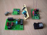 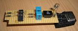 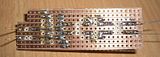 Cheers Jon |
|
Deleted
Deleted Member
Posts: 0
|
Post by Deleted on Aug 18, 2011 15:30:54 GMT
Hi John Nice work That receiver chip looks like a handful to solder. take care |
|
Will
Been here a while!
Ribena abuser!
Member since 2008
Posts: 2,164
|
Post by Will on Aug 22, 2011 18:47:08 GMT
Looking very nice Jon, good stuff. Here's the pcb layout for the Pocket Knife Dac, for those interested. Attachments:
|
|
jonclancy
Been here a while!
Mr. Ripple Eater
Amateur EAGLEist
Posts: 1,131
|
Post by jonclancy on Aug 24, 2011 20:46:47 GMT
Looks good, Will! I added a couple of boards to your spreadsheet, if I'm not too late? I need to brush up on the SMD soldering... Hey Shaun - you can solder that chip using the splurge/solderwick method, but do check the joints with the continuity tester afterwards!! |
|


 Been sitting there in the queue after the Class A boards...


