|
|
Post by freddypipsqueek on Apr 14, 2010 15:40:03 GMT
I have a couple of Theta DIP's - they sit between CD Transports and DAC's and reduce jitter. I have been using them with an optical in and coax out as using the coax in and out is bad as they have a common ground; apparently a bad design. I would like now to use the coax (the DIP's have a switch which allows the sources (optical & coax) to be selected. Having read the net I find that the coax can be used if "the common ground is split"; the jitter apparently crosses the common ground. I have looked in the Theta. The signal wires are soldered to their own respective points on the PCB. The grounds are common (jointed) between the 2 jacks and are then soldered to a single point. See Photo. 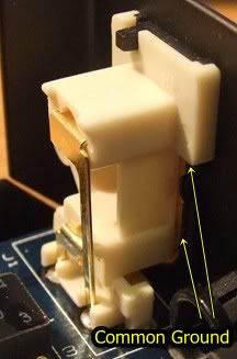 Do I simple need to break the common ground on the basis that both cables (in and out) will remained grounded anyway at the other end ? The net suggested simply replacing the dual sockets with 2 single units however the grounds would presumably be connected to the same point !!. Any advice/comments greatly appreciated. |
|
|
|
Post by freddypipsqueek on Jun 18, 2010 12:33:23 GMT
|
|