xerxes
Been here a while! 
Posts: 1,115
|
Post by xerxes on Feb 13, 2006 10:18:09 GMT
Hi Rick, Thanks for that. After my last post I went away and read up on sealed lead acid batteries. I had assumed that SLA's should be completely discharged before recharging, in the same way as Ni-Cd's. Turns out that this is as about as wrong as you can get and SLA's should be kept topped up to full charge as much as possible. To some extent this removes the need for a charge monitor. The SLA's will probably run the little headphone amp for a day or two. In reality I'm only likely to use it for a few hours at a time and it won't be a problem to pop it on charge when I'm finished. The charger I've ordered is quite sophisticated and will monitor and condition the battery, so it can be left on without worrying about over-charging or damaging the batteries. Having said that, I discovered that you can tell the state of charge by checking the voltage. Could I use an analogue voltmeter, something like this to monitor the output voltage of the batteries: www.rapidelectronics.co.uk/rkmain.asp?PAGEID=80010&CTL_CAT_CODE=&STK_PROD_CODE=M29433&XPAGENO=1 - Item 48-0350, or would having that in place as I've shown in my diagram have a detrimental effect on the power pack? Perhaps I could use a little push-to-make switch to check the voltage periodically, rather than having it permanently in the curcuit. It would look kind of cool in a retro sort of way too.  With regard to the switch, I can't see how I can use a 2 pole switch to achieve what I want. Here's my latest diagram:  I only want the lamp to come on when running on batteries and I also want the the carger to be disengaged, even if I leave it plugged in and powered on. Does that make sense? Lastly, capacitors, have I got these right in the diagram this time? To my novice eye, this looks like they would short the positive to negative and byass the rest of the circuit.  Also, while there is some increased cost, we're not talking a fortune, and RS only sell capacitors in multiples of 5, so I may as well use that to my advantage. If you tell me that 10 x 680uF is better still and will be a real benefit, I'll go with it. |
|
Stormy
100+
Advocates putting smokers in a "Sin Bin"
Needs to learn to keep his big mouth shut.
Posts: 153
|
Post by Stormy on Feb 13, 2006 12:20:09 GMT
Xerxes, just to make you feel better, y gut instincts about the SLAs would have been the same as yours. When I read your post I remembered that car batteries are charged continuously by the alternator to keep them as near to full as possible, rather than only cutting in when they're almost flat! Too many different types of batteries and capacitors in my opinion (and they all work differently!) Stoopid electronics...
|
|
|
|
Post by PinkFloyd on Feb 13, 2006 13:29:11 GMT
Too many different types of batteries and capacitors in my opinion (and they all work differently!) Stoopid electronics... Just to chip in with my 2 cents in this most informative thread. The electronics are not stoopid, each has a place in a particular application, you've just got to find the correct part for your particular application. There you go... my two cents, short and sweet  |
|
rickcr42
Fully Modded
Rest in peace my good friend.
Posts: 4,514
|
Post by rickcr42 on Feb 13, 2006 15:09:41 GMT
because there is no need to switch the grounds when switching the V+ .Having said that ..... makes damn GOOD sense and the present schematic looks is just right for what you are trying to do.all that is left is the current limit resistor for the LED and deciding on if you will add a battery monitor "fuel guage" or not. On the LED front shoot for the lowest current draw device you can find so it uses little battery power.Makes no sense to have the LED use more current than the actual audio circuit  Lastly, capacitors, have I got these right in the diagram this time? To my novice eye, this looks like they would short the positive to negative and byass the rest of the circuit.if a capacitor were a wire you would be right but they are not so your depiction is spot on.When you hook up a capacitor in series,that is where a signal enters one side then comes out the other,you are making a HIGH-PASS FILTER which means your are blocking everything below a certain frequency. Since a DC voltage is also a "0Hz" frequency a capacitor is used in the audio signal path to block destructive DC from mixing with the audio signal and wiping out speakers or headphones.That is a series connection. In a parallel or "shunt" connection as in your schematic you are making a LOW-PASS FILTER which means you are PASSING everything below a certain point but blocking everything above and is why you see tiny little capacitors in RFI/EMI filters in "parallel" connection with the AC line.To block out all the high end crap while passing everything below. (a combination of the above two filters is known as a "band-pass" filter and will pass everything in the middle "band" while filtering out everything else) The way a capacitor does this is by how fast it stores and relases voltage so tiny caps store and relase rapidly while big caps store energy in huge amounts and release it slowly (fast =high freq/slow=low freq). Because of this storage potential a big capacitor is really a BIG BATTERY itself that charges and discharges continously as long as there is a voltage present.Once the voltage is removed the capacitor will discharge at a rate depending on its size/storage capacity.So you can see how wiring it just like the battery and across the battery is really no different than wiring in another battery in parallel with the exception that it has a much lower output impedance than the battery,good for audio work,and stores lesser amounts of power due to it's size limitations. my thoughts exactly I would stick with the 1,000uf all things considered.You gain little going down to 680 other than taking up more space and having to make more connections.There is a point of diminishing returns here until you go to film and foil or oil caps and then the $$$$$$$ increase as the quantity/quality of caps increases. --------------------------------------------------------------------- --------------------------------------------------------------------- --------------------------------------------------------------------- Looks coool to me  excellant idea.thinking is a good excercise You can have the analog meter AND even add in a fuel guage later once all is working or maybe even a simple "GO/NO GO" LED and push button.Many ways to go here and all about choices looks like you are getting close,very close................... rickmonster |
|
rickcr42
Fully Modded
Rest in peace my good friend.
Posts: 4,514
|
Post by rickcr42 on Feb 13, 2006 16:12:56 GMT
how about a combination "cool retro meter" as you have linked above with a simple "low voltage" idiot light ?  simple,cheap,effective and sweet ! Page with the details here : www.reconnsworld.com/power_12vbattmon.html |
|
xerxes
Been here a while!
Posts: 1,115
|
Post by xerxes on Feb 13, 2006 17:19:31 GMT
Hi Rick, First, thanks for all your help so far, this "plonk two batteries in a box and slap a switch on the front" project has grown into something more ambitious than I imagined it would. I'm well aware that electronics "I've just built a pair of my own Krell beating 2Kw mono block power amps!" gurus out there might consider this childs play and a long way off "ambitious".  First the LED I have for the "Battery on" indicator is for 24v and has an integral resistor, so that takes care of that issue. With regard to the analogue voltmeter, thinking about it, I'm not sure it will have sufficient resolution given that the range I want to monitor is just under 24v to just under 26v, low to fully charged. Your low voltage "idiot light" looks more like it, but once again raises more questions. The monitor detailed in the diagram is for monitoring a 12v battery. If I substitute the 6v Zenner Diode of a 12v, will that work? Do I also need increase the the resistor wattage from 0.24w? Do I need to change the value of the resistors? Lastly, the LED for the low voltage indicator, is a standard 5v type going to be OK? |
|
rickcr42
Fully Modded
Rest in peace my good friend.
Posts: 4,514
|
Post by rickcr42 on Feb 13, 2006 18:20:39 GMT
there are ways to make a mechanical meter have resolution to match any digital meter but that better left for another time The "resolution" you worry about is really not so much of a problem anyway since you calibrate to the actual battery in use just as with the "idiot light" and when dealing with batteries these are more ballpark/coarse figures anyway and not micro-reslution just remeber the voltage readout changes with a battery under load and one with no load so when you want to do the actual battery drain test make shure the battery is hooked up to the circuit it will be powering. The other questions are actually answered on the linked page.It shows parts for both a 6VDC and a 12VDC monitor. The adjustment pot for the "sensitivity" or trigger point of the LED is done by simply hitting it with a fully charged battery then backing off until the light goes out.that is the rough set. For the fine set you would use the data sheet from your actual battery so you can see the discharge curve point where the battery maker suggests it be recharged then while in use have a voltmeter hooked up (or an actual voltmeter "in the box" as your first suggestion) and when it hits that magic number adjust for the light to come on right there. The LED. 5V resistor ? Would be fine if you were using 5 VDC only but since you are not you risk blowing the LED out without adding additional current limiting.LEDs last forever when run within specs but are extremely delicate otherwise and do not like a postive over voltage and will let you know it by going dark forever. You will need to add more resistance depending on your final supply voltage.A 12 volt battery is normally more like 13 or more volts unloaded and a 6 closer to 8 so you need to take that into account. SIDE BAR :A battery power supply is not a steady state DC source like a line operated power supply but will drain at a rate determined by what is attached to it.If that "something" had a part that say drew HUGE amounts of current for a short time but a little bit most of the time the battery will actually "sag" during the heavy current event. That means the voltage will drop while it is trying to provide the additional current (the V/A rating of the battery). When this "event" is over the battery will ramp right back up to full voltage and tick along steadily until the next such event. Thatr is why a battery power source can not be considered a steady state power supply like a line operated on would be.The mains may "sag" during a brownout condition but usually are spot on no matter what you plug in.Regulation tightens this up even more and is why you see it used for everything from computers to audio : A known voltage at all times no matter what. Kinda makes it sound like batteries suck until you consider MUSIC is also not a steady state signal but a dynamic one that changes from moment to moment and why batteries work and sometimes not just well but better than the mains power source which along with the voltage brings a load of crap riding in on the same wire.Everything in your building and maybe even on your block that is plugged in is also plugged into your AC outlets unless you take steps : Filtration,etc. Bet you wish you didn't ask huh ? don't kid yourself man.Most of those "gurus" have no clue either but like to sound like they do by throwing out confusion.Works on the electronic no-nothings but actually pisses me off on some levels because in their ignorance they set out to confuse an already confusing topic so they don't get caught looking stupid. most of this crap is really just plug 'n play. It SEEMS like a bitch at first but one day the realisation just snaps into place and you feel REALLY stupid for not seeing it earlier and we all go through it. Baby steps.Gotta crawl before you can walk and walk before you can run then once up to speed you work on your endurance so you can leave the sprinters in the dust (hey Mike ! If you want me to post here man you need to provide me with a serious devil smiley which if available I would have inserted here dammit ! ) |
|
|
|
Post by PinkFloyd on Feb 13, 2006 18:32:30 GMT
There you go buddy, good enough or a tad "OTT"?
Edit: sorry to lower the tone of this excellent thread.
EDIT: removed that avatar so you may approve it before it goes "live" ;/j
|
|
xerxes
Been here a while!
Posts: 1,115
|
Post by xerxes on Feb 13, 2006 18:49:31 GMT
Hi Rick, I think I'm missing something here. The linked article is for a 12v battery monitor: www.reconnsworld.com/power_12vbattmon.html and mentions reducing the voltage of the Zener diode for a 6v battery monitor. I need a 24v battery monitor, so wouldn't I have to increase the value of the zener diode, and possibly the wattage too? I'm also baffled by the LED thing, which is why I got one with a built in resistor for 24v for the "battery on" indicator. |
|
rickcr42
Fully Modded
Rest in peace my good friend.
Posts: 4,514
|
Post by rickcr42 on Feb 13, 2006 19:15:23 GMT
Over the Top Mike ? Hell boy ! you are dealing with the RICKMONSTER here ! Lose the smoke and maybe add some bulging eyeballs and we can deal son  |
|
rickcr42
Fully Modded
Rest in peace my good friend.
Posts: 4,514
|
Post by rickcr42 on Feb 13, 2006 19:22:45 GMT
Voltage yes.Wattage no.not unless you plan to power a "monster" amp. 12 Zener for 24 VDC operation (or two 6 V Zeners in series,same thing) for future LED reference bookmark this page : led.linear1.org/1led.wizor this one if you want to get crazy (insert devil here) : www.quickar.com/noqbestledcalc.htmHEY DAMMIT ! Hooo yooo callin' "Low Tone" ? |
|
|
|
Post by PinkFloyd on Feb 13, 2006 19:27:28 GMT
Over the Top Mike ? Hell boy ! you are dealing with the RICKMONSTER here ! Lose the smoke and maybe add some bulging eyeballs and we can deal son "Smoke"? Have you seen your avatar, are we discussing the same thing here? Mike |
|
Stormy
100+
Advocates putting smokers in a "Sin Bin"
Needs to learn to keep his big mouth shut.
Posts: 153
|
Post by Stormy on Feb 13, 2006 19:56:56 GMT
I love it really, I've just always found it harder to understand and visualise than mechanics. I realise it gets much easier with practice, as with anything - I've only recently discovered that soldering is easily reversible with the right tools, and that should encourage me to experiment a bit more! |
|
xerxes
Been here a while!
Posts: 1,115
|
Post by xerxes on Feb 13, 2006 20:04:04 GMT
Sheesh, and I thought you guys "knew" all this stuff, or worked it out on a napkin. ;D Thanks for that, bookmarked! This recommends a 1w or higher, 1.2K resistor for a 2.0V@20mA LED, so should I swap the two 1K resistors R2 and R3 for these? |
|
rickcr42
Fully Modded
Rest in peace my good friend.
Posts: 4,514
|
Post by rickcr42 on Feb 14, 2006 16:05:56 GMT
sounds about right but maybe 1.5K would be even better considering a battery is not a tightly regulated voltage source and can have "spikes" in the voltage under a dynamic load (music) between the "sag" of a heavy passage and the recovery stage of the battery
|
|
rickcr42
Fully Modded
Rest in peace my good friend.
Posts: 4,514
|
Post by rickcr42 on Feb 14, 2006 16:08:14 GMT
I wish ! I have enough problems without the added burden of having to actually KNOW this stuff  ;D |
|
xerxes
Been here a while!
Posts: 1,115
|
Post by xerxes on Feb 14, 2006 17:23:57 GMT
Thanks for all your help Rick.
I've ordered all the parts and they should arrive in a day or two.
When I've finished cobbling everything together I'll post up some pictures so that all the people that helped can see the results of their input, or maybe just have a good laugh. ;D
|
|
rickcr42
Fully Modded
Rest in peace my good friend.
Posts: 4,514
|
Post by rickcr42 on Feb 14, 2006 21:43:10 GMT
very cool I look forward to the final product being displayed in all its glorious details |
|
xerxes
Been here a while!
Posts: 1,115
|
Post by xerxes on Feb 16, 2006 13:25:06 GMT
Hi Guys, I think I have this right, but could someone check it for me:  The Zener Diode is blue at the right end, black the other and the transistor has the flat side with the writing on uppermost. Does that match this: Probably didn't need those dirty great 3W resistors though.  |
|
rickcr42
Fully Modded
Rest in peace my good friend.
Posts: 4,514
|
Post by rickcr42 on Feb 16, 2006 14:27:37 GMT
Almost..........but not quite The Zener : 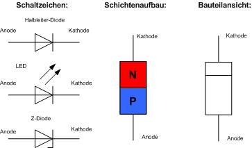 The 2N3904 :   |
|
xerxes
Been here a while!
Posts: 1,115
|
Post by xerxes on Feb 17, 2006 0:00:00 GMT
Funny, it was the pot I wasn't entirely sure about, turns out that's the only thing I got right. The transistor is straight forward now I've seen that picture, but what about the diode? This illustration I found is confusing:  Is the end with the lettering always positive? |
|
rickcr42
Fully Modded
Rest in peace my good friend.
Posts: 4,514
|
Post by rickcr42 on Feb 17, 2006 0:37:36 GMT
Your illustration above is correct but your previous photo is off. It shows the "kathode",the little blue band end,oriented the wrong way.It should attach to the pot "wiper" with the Anode of the Zener connected to the base of Q1. think of the band on the part as being the same as the "collar" (straight line) in the schematic drawing of the part |
|
xerxes
Been here a while!
Posts: 1,115
|
Post by xerxes on Feb 17, 2006 2:08:16 GMT
OK, I think whats throwing me is that the diodes I have are pretty much half blue and half black, so you could interpret that as a blue band on a black background or a black band on a blue background, if you see what I mean. If I look closely I guess the blue "half" is larger, so the black is the band corresponding to the - cathode. Right? |
|
rickcr42
Fully Modded
Rest in peace my good friend.
Posts: 4,514
|
Post by rickcr42 on Feb 17, 2006 4:26:53 GMT
The blue end is the Kathode according to the MELF or Mini-MELF package codes.This particular diode is a Mini-MELF using the Vishay/General Semiconductor code www.marsport.demon.co.uk/smd/sod80.htm |
|
xerxes
Been here a while!
Posts: 1,115
|
Post by xerxes on Feb 19, 2006 16:57:45 GMT
Well, I've assembled the battery "power pack" and it works - hurrah!. A blue LED lights when the batteries are being used and I've set a red LED to light when the voltage of the battery drops to just below around 24v, to tell me when it needs charging. Although I will need to check the voltage a few of times with a meter and fine tune the adjustment of the low voltage indicator. Turns out the blue end of the diode I have is the cathode. This is the one I bought: www.rapidelectronics.co.uk/rkmain.asp?PAGEID=80010&CTL_CAT_CODE=30389&STK_PROD_CODE=M31547&XPAGENO=1, code BZX85C12V. This is a DO-41 package, so it's obviously different to the Mini-MELF you mentioned. In any case I tested it with the blue end as the calthode, turned the the pot and hey presto the lamp came on, so I connected it up properly this way round. Given that a zener diode only allows current to flow in one direction, I assume if it were the wrong way round that the LED would never light, no matter what the position of the pot. Is that correct? In any case, thanks for all your help Rick, I couldn't have built it without your assistance. I missed a component when I ordered all the bits, I forgot to order a DC socket for the mains PSU input. I've ordered one and it should arrive in a day or two. When I've added the DC socket, I'll post up some photos. |
|


 ;D
;D 