|
|
Post by rod on Dec 18, 2004 21:03:09 GMT
Mike You mentioned in the Head-Fi WNA thread about reducing the crossfeed in size (it is pretty small as it is!). Have you done this yet? Also, has anybody installed one in their WNA with switching? Being a beginner, I have lots of ambition, but need an idiots guide and lots of pictures to get moving.  PS. I could really do with a couple of cool beers right about now, but I'm on call and telly is crap. But that's ok, I can come here and ask daft questions, whilst listening to (amongst others) B.O.C. ;D |
|
|
|
Post by GoRedwings19 on Dec 26, 2004 1:34:19 GMT
I am not very technical but what is the purpose of crossfeed? I am old school and believe there should be nothing in the way of the signal path. Therefore giving the clearest signal possible.
|
|
|
|
Post by PinkFloyd on Dec 26, 2004 15:58:30 GMT
I am not very technical but what is the purpose of crossfeed? I am old school and believe there should be nothing in the way of the signal path. Therefore giving the clearest signal possible. Crossfeed will throw the soundstage silightly forward out of your head making for an altogether more natural listen (more like listening to speakers) It's particularly useful when listen to extreme stereo recordings such as some of the Beatles stuff. Jan Meier explains it very simply home.t-online.de/home/meier-audio/crossfeed.htm |
|
|
|
Post by PinkFloyd on Dec 26, 2004 16:05:28 GMT
Mike You mentioned in the Head-Fi WNA thread about reducing the crossfeed in size (it is pretty small as it is!). Have you done this yet? Also, has anybody installed one in their WNA with switching? Being a beginner, I have lots of ambition, but need an idiots guide and lots of pictures to get moving. Hi Ron, I'm going to get around to fitting one shortly and will upload pics and diagrams which will make it simple to follow. There's no real need to make the board any smaller as you are right in what you say "it's pretty small as it is" I've already got a makeshift tutorial here: www.rock-grotto.co.uk/x-feed.htm and a diagram of the switch here: www.rock-grotto.co.uk/crossfeedtips.htm it's a a 2x4 switch - direct feed in one position and x-feed in the other ..... forget the reference to an on off on switch that's a typo and will be rectified the next time I have dreamweaver open ;D Mike. |
|
suzywong
<100
The Man With No Naim
The Man With No Naim
Posts: 9
|
Post by suzywong on Jan 3, 2005 23:48:29 GMT
Mike,
do you think a crossfeed will enhance a WNA?
I knocked up one of your Lite versions of the JM design just before Xmas......not had much chance of extended listening tests so far (usual impediments...xmas, kids, new cat, mothers-in-law etc etc), but it was very interesting, and I'm only using a CMoy driving very old Senns. I think it will get more interesting when I start down the (provisional) WNA/HD650 track (whenever the bank has recovered from Christmas.......)
Happy new year
chris
|
|
Alick
<100
The Fife Panther strikes again!
Posts: 41
|
Post by Alick on Jan 4, 2005 1:03:39 GMT
Suzy - I'm the proud owner of a new set of HD650s (Christmas present) and I had every intention of building a crossfeed into my WNA during the Christmas holidays but I spent too much time listening and none modding. I'll be building it sometime in the coming weeks (I have all the components and no excuses) so I'll post here when I've done so with my impressions.
|
|
|
|
Post by rod on Jan 19, 2005 22:23:35 GMT
Ha-ha-ha! I was playing Dr. John's Gris-Gris album the other night. Right from the start - Dr. John squarely in the middle, all instrumentation on LH channel, backing vocals RH channel. I thought, lets give the crossfeed a go and see what happens... ...Ha-ha-ha! It was in the loop all the time, when I disconnected it, things got worse. I like the crossfeed effect on other albums, but I think an extra strong version is needed for this album.  Any ideas for increasing the effect? Ta |
|
|
|
Post by rod on Jan 23, 2005 15:22:44 GMT
Mike
I'm sure I saw how to alter the crossfeed effect somewhere. It might have been yourself. Any chance of a point in the right direction?
|
|
|
|
Post by PinkFloyd on Jan 23, 2005 15:39:36 GMT
Mike I'm sure I saw how to alter the crossfeed effect somewhere. It might have been yourself. Any chance of a point in the right direction? Sure Rod, Your crossfeed is "medium" crossfeed, if you want "high" crossfeed then do the following: Change the 2 k resistors to 4.4 K Change the 220nF caps to 100nF Change the 47nF cap to a 22nF cap The 330R resistors remain That will throw the sound out of your head a bit more  All the best. Mike. |
|
|
|
Post by rod on Jan 23, 2005 15:44:02 GMT
Thanks Mike,
I think I might have seen an amp on Head-Fi with switchable crossfeed (on / off, and varying crossfeed). How difficult would this be for me? Head-Fi is so huge, I would be unsure where to start looking.
The Dr John cd above was a right laugh!
|
|
|
|
Post by PinkFloyd on Jan 23, 2005 15:57:31 GMT
Hi Rod, I hope this diagram makes sense, if not I'll explain later as I'm as sick as a parrot at the moment and off to bed:  |
|
|
|
Post by rod on Jan 23, 2005 16:00:21 GMT
Cool, get well soon! Hope it's not self-induced...  |
|
|
|
Post by PinkFloyd on Jan 23, 2005 20:02:20 GMT
Hope it's not self-induced... Nah, not self induced on this occasion Rod, the last 6 days I've had serious pain behind my left eye which gets worse if I move my eye to the left or right or up and down..... it's also painful if I tilt my head or stand up or sit down.... in a word "painful" I tried a lot of different painkillers which didn't help much and this afternoon I tried these things called "Tylex" popped 4 of them down me and after about 30 minutes I felt like I was floating on the ceiling and felt extremely ill... I don't know what's in these buggers but one things for sure, it ain't aspirin  Actually just reading that.. yeh it probably was self induced! Anyways I had a good sleep and appear to be ok apart from the throbbing in the eye  |
|
xerxes
Been here a while! 
Posts: 1,115
|
Post by xerxes on Feb 6, 2006 17:25:17 GMT
Hello Mike,
Having read your glowing reviw of the WNA headphone amp I recently ordered one, together with a set of Sennheiser HD 650's and I'm really pleased with them. Having no knowledge of electronics and never having soldered anything more complicated than a few DIY audio leads I ordered the amp assembled.
However, looking around your site sparked my interest and I wanted to build something. I've just built the little Meier audio crossfeed as per the instructions on your site. I wasn't sure what components to use, so I used the same RC55Y resistors and RIFA Polypropelene capacitors that are used in the WNA amp itself - was that a good idea, or should I have chosen something else?
The crossfeed works fine, but I find the effect quite subtle. I'd like to build the one detailed in the diagram above with a bybass and two different levels of crossfeed, but I have a few questions:
1. I'd like to use a rotary swith to select the bypass and the crossfeed levels. I was considering using a 2 pole switch. I would use the 2 poles for the left and right channels. The ground would be common for both channels and go from the input phonos to the output phono connectors and from the input phonos to ground on the crossfeed circuit. Should this work?
2. Given that I found the effect of the original filter quite subtle. I assume that I could create a greater level of crossfeed to that detailed in your diagram by changing the values of the resistors and capacitors. What values would I need to change the 4.4k resistors, the 100nF capacitors and the 22nF capacitor to to give me an even higher level of crossfeed.
3. Silly question, where can I get some good hook up wire suitable for high quality audio? In the original crossfeed I built I used some spare teflon coated OFC copper wire from a Kimber PBJ interconnect I had canabalised to make a 2 RCA to mini jack connector, but this is very stiff and awkward to work with.
Lastly, the WNA amp came with a dinky little 24v power supply. While the amp already sounds good, I suspect that it might sound even better with a better quality power supply. WNA suggests using a couple of 12v sealed lead acid batteries in series, but this sounds a bit of a plaver and I would prefer a mains solution. I was considering using a Creek OBH-2 PSU, what do you reckon?
|
|
|
|
Post by PinkFloyd on Feb 8, 2006 13:05:29 GMT
I wasn't sure what components to use, so I used the same RC55Y resistors and RIFA Polypropelene capacitors that are used in the WNA amp itself - was that a good idea, or should I have chosen something else? Perfectly good components, the RC55Y has a very low temp coefficiency and the polyprop caps are absolutely spot on for the job...... possibly the best parts you could have chosen. The crossfeed works fine, but I find the effect quite subtle. The effect is subtle, you really don't want something that isn't subtle as it totally shags the soundstage. 1. I'd like to use a rotary swith to select the bypass and the crossfeed levels. I was considering using a 2 pole switch. I would use the 2 poles for the left and right channels. The ground would be common for both channels and go from the input phonos to the output phono connectors and from the input phonos to ground on the crossfeed circuit. Should this work? No, it won't work. You need a 4 pole switch as shown. You may think a 2 pole switch will work but it won't, the 4 pole switches are available from Maplin I believe.  2. Given that I found the effect of the original filter quite subtle. I assume that I could create a greater level of crossfeed to that detailed in your diagram by changing the values of the resistors and capacitors. What values would I need to change the 4.4k resistors, the 100nF capacitors and the 22nF capacitor to to give me an even higher level of crossfeed. I wouldn't advise you to even go there. The effect is meant to be subtle and not in your face / bells and whistles. Get hold of the Beatles - Magical Mystery Tour album and listen to track 3 "flying" Listen to it firstly without crossfeed and then listen to it "with" crossfeed in circuit, you will see the effects of crossfeed on this type of recording is pretty "dramatic" and it corrects heavily panned / extreme stereo recordings very nicely. With normally recorded tracks you really shouldn't hear a lot of difference, this is the idea, it really only should become obvious it's working when listening to extreme stereo recordings like some of the Beatles stuff etc. It "really" shouldn't be that obvious with normal recordings, just enough to take the fatigue out of listening, any more will just ruin the music. 3. Silly question, where can I get some good hook up wire suitable for high quality audio? In the original crossfeed I built I used some spare teflon coated OFC copper wire from a Kimber PBJ interconnect I had canabalised to make a 2 RCA to mini jack connector, but this is very stiff and awkward to work with. Again, Maplin supplies some good hook up wire. David White of WNA david.white38@ntlworld.com has some great stuff he ships with the WNA I'm sure he'd send you a few metres, it's really good cable and totally flexible and heat resistant (you can hold the soldering iron on it for ages and it will never melt) absolutely ideal stuff for amps / crossfeeds. Lastly, the WNA amp came with a dinky little 24v power supply. While the amp already sounds good, I suspect that it might sound even better with a better quality power supply. WNA suggests using a couple of 12v sealed lead acid batteries in series, but this sounds a bit of a plaver and I would prefer a mains solution. I was considering using a Creek OBH-2 PSU, what do you reckon? The Creek OBH-2 PSU should be fine, even better is the Calex PSU and I happen to have one for sale..... it really brings the best out of the WNA, superb PSU. 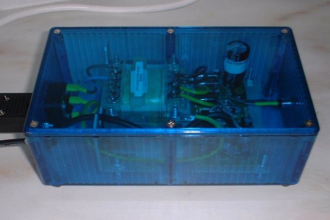 Calex in blue transparent Hammond enclosure Mike. |
|
xerxes
Been here a while!
Posts: 1,115
|
Post by xerxes on Feb 8, 2006 16:36:18 GMT
Hi Mike, I changed my mind about the PSU and I've gone the battery route. I was originally put off this idea because I could only find 12v chargers, which would mean disconnecting the batteries and charging each individually. However, I found a company that will supply a 24v lead acid battery charger (CM03A24) for £24.95: www.tremacoproducts.com/4655/11442.html. This will save me disconnecting the batteries when I need to charge them. What I intend to do is fit a 2 pole 2 position on-off-on switch on the front of the battery enclosure with one position for charge/off and the other for on/run. I’ll also fit a socket to the front of the battery enclosure to plug the charger into, that way the “charge” position can double up for “off” when the charger isn’t connected. I spoke to David at WNA and he reckons the amp will run for 2-3 hours on a couple of 9v PP3’s, so it should run for days on a couple of 2.2Ah 12v lead acid batteries. Having said all that, if I don't like the whole battery thing, I might take you up on the Calex.  I took another look throgh the WNA catalogue and ordered some cable and some extra resistors and capacitors. They're slightly dearer than at RS Components, but RS only allows you to order resistors in multiples of 5 and capacitors in multiples of 10. I don't understand why I can't use a rotary switch for the crossfeed bypass/level selection. Here's a diagram:  If this works, surely I don't need the 3rd pole and ground can just be common right accross? With regard to the subtlety of the crossfeed, I'll take your advice on this. I've never heard one before and I guess I was expecting something more dramatic. Personally I've never found listening to headphones fatigueing, so that isn't a concern for me. However, a lot of people mention soundstage in reference to headphones and I just don't get that. My system is capable of producing a pretty good soundstage through my speakers, separate instruments and voices can be quite easily located in space and are clearly defined with plenty of "space" around them and with the right recording there is a fair amount of depth to the image too. With headphones, I've never really managed to get anything other than a miniature band playing somewhere in my head, occasionally I will hear a sound out to the extreme left or right, but never really in front of my head. |
|
|
|
Post by PinkFloyd on Feb 8, 2006 19:20:08 GMT
I won't spend time typing as I'm tired but will instead quote from my good friend rickcr42 on the subject of switching out crossfeed, hope this explains it better:
"About four years ago ,maybe longer, I pointed out in the headwize forums that using the switching patterns then commonly used the crossfeed is always in circuit unless either a 4PDT switch was used (four pole double throw) or a three deck rotary.
This kind of caught most by surprise but when it was looked at the "glitch" was right there to see.
While the caps, the frequency selective action of the crossfeed, were being defeated the resistor blending was still taking place and the stereo separation was being comprimised.
This is of minor importance with a totally headphone specific system and the blending could actually be considered a plus.
But if used with a home stereo system connected in the common manner for a headphone amp the record output is ALWAYS BLENDING the channels, even when listening to loudspeakers due to the interchannel blend going on pre-volume control.
Two options i mentioned above.
A couple of more fixes are to add a simple SPDT switch in a "black box" on the record output to "open up" the signal ,isolate it entirely when not in use (recrod mute)
But when you wanted a record feed to a recorder you would still have this problem of interchannel blending.
Another method ,one i like actually, is to use dual DPDT switches.
One switches the crossfeed capacitors out and the other switches the crossfeed resistors out so what you get is:
all switches down : stereo operation
left switch up : slight blending of the channels
left and right switch up : full crossfeed
It is cheaper and easier to find two DPDT switches than it is to locate a good 4PDT switch so this may be a good option for some plus it is a true defeat when all switches are up PLUS it allows total control of the stereo signal ,especially if you take it a step further and add a mono switch. "
Rickcr42
|
|
xerxes
Been here a while!
Posts: 1,115
|
Post by xerxes on Feb 8, 2006 22:11:04 GMT
Right, gotcha. I was looking in the wrong place, I thought that the problem was with the ground; you have to remember I'm a complete noob. But the problem is that part of the crossfeed circuit is still engaged, like this:  Right? So what I need is this:  Where the DPDT switch completely bypasses or engages the crossfeed filter and the rotary switch can be used to select the bypass, medium and high crossfeed setting as detailed in the Linkwitz circuit diagram. Lastly, if this will work, should I use a make-before-break, or a break-before-make rotary switch? |
|
Stormy
100+
Advocates putting smokers in a "Sin Bin"
Needs to learn to keep his big mouth shut.
Posts: 153
|
Post by Stormy on Feb 9, 2006 21:44:24 GMT
Sorry to butt in, but I was interested! Looks like it should work to me, although "bypass" on the rotary switch should now be labelled something like "low" due to the aforementioned bleeding effect still being present in this position!
As you're switching audio, and there is no chance of anything being damaged by momentary short-circuiting, I'd say you'd be better off with MBB switches to avoid potentially damaging "pops" in your headphones (ears and drivers).
Maplin sell a plastic-shafted MBB 4-pole 3-way (code N91BX) for £1.49, or you can often pick up metal ones on eBay for very little.
Just in case you were considering it for the sake of neatness, things would get very complicated and expensive if you were to try to combine the two switching stages in one rotary (ie. off-lo-med-hi), as you'd need to use a two-wafer switch, which costs about £13 from RS in kit form. I made one recently for the bass guitar I'm building, as I wanted to have one rotary switch to change the output modes on two pickups simultaneously in each of the four possible combinations, and that requires a 4-pole 4-way (the switch can actually do 5 ways, but I limited it to four as I didn't want an "off" position). Simple on the outside, but expensive and complicated within! I spent ages trying to find alternatives, but everything was BBM except for a Fender-style blade "Superswitch", which I don't like because they are easily knocked between positions while playing guitars.
Good luck!
|
|
xerxes
Been here a while!
Posts: 1,115
|
Post by xerxes on Feb 9, 2006 22:45:54 GMT
"bypass" on the rotary switch should now be labelled something like "low" due to the aforementioned bleeding effect still being present in this position! I agree, the DPDT toggle switch either completely bypasses or engages the crossfeed circuit. The rotary switch will give me 3 different levels of crossfeed only when the circuit is engaged. When bypassed, the rotary switch will obviously have no effect. I simply labelled the inputs to the crossfeed cuircuit as BYpass - MEDium-HIgh in my diagram to correspond to those indicated on the Linkwitz crossfeed cuircuit diagram: I've ordered all the necessary parts, so I'll post up a picture of the unholy mess when I've put it together. ;D |
|
rickcr42
Fully Modded
Rest in peace my good friend.
Posts: 4,514
|
Post by rickcr42 on Feb 12, 2006 14:17:54 GMT
Mikey's "Freind' responds ;D First off,the only way to totally eliminate a cross-feed network from a stereo line is to use three poles of switching for a simple single-position crossfeed and for the above schematic a four pole switch so you can add a "break" between the two 2.2K resistors. To not do this you still have a slight blending of the left and right channels only now it is across the board at all frequencies rather than just the crossfeed turnover frequency since the actual "filter" is already bypasses by the above. Not neccesarily a bad thing if you are only using headphones but if it is a "mixed system" where everything passes through on its way to either a headphone amp or a loudspeaker amp you just closed in the stereeo spread with speakers so not so good. There is also the need by many (me) to have a TRUE bypass of any effect when it is not being used just to ahve the pure and unmodified signal available s again you need a "break" at the junction where the L-CH 2,2K and R-CH 2.2K resistors meet. Reading the rest of the thread to figure out what you are trying to do but this jumped out at me so i had to respond |
|
rickcr42
Fully Modded
Rest in peace my good friend.
Posts: 4,514
|
Post by rickcr42 on Feb 12, 2006 15:04:42 GMT
"Battery Power Supplies for Audio" by The Rickmonster  There are a lot of sound reasons (pun intended) for using an SLA battery for audio circuits but only if you do it right or you end up with a very dull and uninvolved sound,the dynamics go south,and the reason is output impedance. Properly designed a mains operated power supply will have a serriously low output impedance and this is essential for rapid power delivery and driving the actual circuit much as a low output impedance in an audio circuit is required to drive the next stage in the audio chain.Batteries fall short in this area and even in the portable device arena (iPODs,Palm Pilots,Cell Phones) are followed by some kind of regulator to both stabilize the voltage and lower the impedance of the battery for efficient DC delivery. Fine for mass market consumer level gear,not so fine for high-quality audio mostly so what to do ? The old "toss a capacitor on 'er" trick ;D Put a large ultra-low impedance electrolytic across the output terminals,say an OS Con or low Z Panasonic of around 4,700uF per polarity right across each battery terminal for a big SLA and maybe 1,000uf for smaller batteries. Low impedance is the territory of the audio circuit power supply and only current sources for active stages should have a high impedance. that takes care of the "how do I make it sound good" part.The harder question is "how do i actually make this sucker work for me hassle free ?" and that brings us to the actual charging and switching circuits being discussed here so....................................away we go................... First of all using a battery power supply totally eliminates mains artifacts from the audio signal and those "artifacts" are not just your usual noise and hum but crap you never know is there but the abscense of you WILL notice in many cases so why not use battery supplies for all things audio ? the above dynamics limitation,the pain in the ass nature of not having your music "ready to rock" any time,any where ('cause the damn batteies are charging !) and finally,not the least consideration,COST ! A cheap path this is not and if you want to do it rght you need to consider the batteries,the charging circuit,adding a monitor to the batteries so you know WHEN to charge those puppies (instead of guessing or suffering sh*tty sound until it dawns on you why...). An "All Out" solution would be a low voltage monitor that would not only tell you when the batteries need charging by lighting a panel indicator (LED) but also switching in the charger and even better the battery supply "off" and a mains supply "on" so there is no interrption of the audio other than a required 20 second or so audio "mute",also automated,while this transistion is taking place or you could get some serious nasties through your system. Then when the "ready" light comes on switch back to battery operation and kep on jamming.That is the overcomplicated idealised version. The "OK.I can build that with out killing my brain cells" quick and dirty version would be: 1-Battery section with "low voltage" monitor LED 2-Dual function power switch on the crossfeed:Position #1 to DC Input #1 (wall wart),Position #2 to DC Input #2 (battery) 3-Charge switch on the battery (or automated charging "triggered" by the Low V LED) You NEVER want to switch audio and power with the same switch untless it is an all-or-nothing total ON or total OFF state or you open yourself up to some serious popping and/or other signal fk-ups during the changeover. Lot of ways to come at this but I personally would shy away from the all-in-one switching solution and go with simple or if complex,automatic switching.If single power supply/battery operation is a must then rather than disengage the batteries while charging I would just run the charger in parallel with the actual circuit.that is batteries still active while charging which hurts nothing yet simplifies a lot. Rickmonster out |
|
xerxes
Been here a while!
Posts: 1,115
|
Post by xerxes on Feb 12, 2006 15:19:40 GMT
I can see how using a 4th pole to create a switch between the two 2.2k resistors would work, but as I now have the parts I'll stick with the combination of a 4 pole toggle to completely bypass the crossfeed curcuit and a 3 pole rotary switch to select the level when it's engaged.
My CD player has two sets of phono outputs, so I have the headphone amp connected to one set and my main amp to the other. As such, permanently engaged crossfeed wouldn't be a problem, but I'd like to be able to switch it out completely if I want to.
|
|
xerxes
Been here a while!
Posts: 1,115
|
Post by xerxes on Feb 12, 2006 20:28:47 GMT
Thanks for your input, however you've raised a few questions. First, I have no idea how to build a low voltage indicator, I'm a complete beginner and don't really know what I'm doing; I can just about "assemble by numbers". It would be nice to run the amp from the mains without having to unplug the battery pack, should the batteries be flat when I want to use it. Here's what I've come up with:  Using a 4 pole double throw, on-off-on toggle switch, I can set the amp to run from the mains PSU when charging. I can also leave the amp on, running from the mains PSU to keep it warmed up when the charger is unplugged. The LED will serve as a visual reminder that the amp is running on batteries. 1. The batteries are 2 x 12V 2.2 Ah wired in series, the 4 pole toggle switch is rated 3A at 250VAC 6A at 125VAC, is that sufficient? 2. Would Panasonic FC series Al electrolytic cap,4700uF 25V 105deg C, RS Part number 315-0669, be correct, or do I need a higher voltage? In which case, how about 2 x 3,300uF 35V in place of each single 4,700uF or possibly 2 x 2,2000uF? I'm guessing that capacitors can be be wired in parallel, to increase capacity, like batteries. 3. I understand that electrolytic capacitors have a polarity, have I got them the right way round in my diagram? As you can tell I'm groping around in the dark a bit, so any light shed is much appreciated. |
|
rickcr42
Fully Modded
Rest in peace my good friend.
Posts: 4,514
|
Post by rickcr42 on Feb 13, 2006 5:54:15 GMT
as was my intention We all have to "begin" somewhere and hopefully we pick up enough knowledge along the way to enable us to make that "leap" telling us what we need so we can set out to make it happen. It is the know it all expert with a closed mind that is dangerous,not those who want to learn because the former ends discussion while the latter enables it. On the battery monitor I will see what I can dig up as far as plans go.It really is a useful item to add to any project using batteries or how else to know when you are discharging the batteries too deeply thus damaging them ? A step further the very same "trigger mechanism" that lights a panel indicator can be used to make the charging circuit automatic with a couple of cheap parts.Again I will see what i can dig up and post here. the cool thing about DIY is you can think about every possible feature you would like to have then just add it in ! No commercial product (other than possibly my own if they ever hit the market ) I know of thinks not just about how to make a thing work but how to make it work in any possible situation without being a pain in the ass ! This does not mean it has to be expensive just well thought out and to me personally it makes zero sense to not have at least the OPTION of an mains operated supply for those times when the batteries are being charged or replaced. you have the right idea with the 4PDT switch but have overcomplicated the simple AND have your poles wrong.the way you have it you have simultaneous Mains supply/battery supply in parallel or nothing ! Better a simple (and way cheaper) heavy duty DPDT with the "top" terminal pair going to the battery supply (+ and -),the bottom set going to the mains operated supply (+ and -) and the center center lugs (the switching pole) going to the LED/resistor then on to the actual amp. flip up=mains DC/flip down=battery DC and if you get a "center off" version then the center will be just that,off. then it will look like : 0 0 mains supply
0 0 off
0 0 batteryAbsolutely all of the above are valid with the exception of the 25 volt rating.most likely your batteries will be rated 12.6DC or better unloaded and that would mean a 25 volt capacitor not high enough but 35V,50V even 100V is fine as is "stacking" multiples. In fact,stacking five 1,000 uF capacitors is WAY better than a single 4,700 uf cap for power supply bypassing because the smaller cap will have a lower series resistance,a lower internal inductance and a lower ESR so the only drawback is cost and chassis space. Taking this to the ultimate would be to parallel 10uF film caps in enough quantity to equal the 4,000 or so uF total but the cost would be a real burden so it is seldom done even in expensive gear even though it is well known it is the preferred method. not as drawn presently.this is an area where you want to be VERY careful because the result if you are wrong is a blown part and electrolytics blow in a spectacular manner ! I once wired a 4,700uF 75 volter backwards and it actually whistled before it blew up and started oozing white goo ;D Looking at the back of a DPDT toggle switch keep everything "+" polarity to the left side terminals and everything "-" (the grounds) to the right and you can not go wrong.when i say "everything" I mean both power supply inputs,the power output,the capacitors and the LED/Resistor combo. I like to draw a life sized layout on paper,place all the parts on that paper in the areas where they are drawn in then make the connections with a pencil umtil i get it right. Something about actually having the parts in hand while doing the layout is soothing to me and is a good way to avoid foul ups because unlike a two dimensional monitor layout it is "Real-Time 3D" and you get more of a feel for it.at least i do anyway. i'll do what i can to be of help.i always enjoy watching a beginner go from "I don't know doo doo" to working project to be proud of.DIY audio is very cool but you gotta take it in small bites at first or you could end up overwhelmed by it all and then frustration sets in then the next stage is you walk away pissed off.Trust me I KNOW frustration but i also know if it is worth doing it is worht doing right and that takes time and patience Rickmonster out |
|