|
|
Post by dicky on Sept 13, 2012 19:38:53 GMT
This should do it. Attachments:
|
|
Deleted
Deleted Member
Posts: 0
|
Post by Deleted on Sept 14, 2012 7:33:10 GMT
|
|
layums
100+
Thank you for the untips
Just started electrical fixing, to go with my other fixing bad habits :)
Posts: 111
|
Post by layums on Sept 14, 2012 8:54:03 GMT
Just awesome.this could be my chance to learn how to read a schematic. Got photos, waiting for someone to do the mods.its a nice little project for me to get learning on. Thanks guys.
|
|
mrarroyo
Been here a while!  Our man in Miami!
Posts: 1,003
|
Post by mrarroyo on Sept 14, 2012 10:07:50 GMT
So the green 20 ohm resistor in the picture posted by dicky is the one I have to install? What are its specs? Thanks.
|
|
|
|
Post by PinkFloyd on Sept 14, 2012 10:13:32 GMT
Good clean juice too Frans.... 500 hours of aural bliss and then a simple case of recharging the battery for another 500 hours of sonic pleasure etc. etc. Sure, it doesn't exactly say "portable" and should be hidden away in a car BUT if you're using the amp at work you could keep the auto battery there as a power station.... I was being serious (by the way) the car battery may be just what Miguel is looking for.... 500 hours is 62 days listening @ 8 hours per day PER charge... not bad!!
|
|
|
|
Post by dicky on Sept 14, 2012 12:11:03 GMT
Thanks for the recommended changes, Frans! I'll have a go at those, but I need to order the parts. The electrolytics are fair enough in the regulator circuit and on the chip (does it really need 35v?) - but what do you recommend for the other 3 caps (100nF x 2 and 10nF x 1) - there are so many types!  Also, I have a few questions: 1. I have fitted a log pot - the original pot was too scratchy. Of course it isn't optimised for this circuit - I assume the 1k8 mod won't work for the log pot? 2. Should the LED in the recommended changes be also in the original drawing? I assume this is not an additional item? 3. What current/power will the 20k pots need to handle? 4. Can you confirm I need to revert to 10 ohms heater resistor? I'll start with the regulator mod to get the heat down as I'm getting through quite alot of shirt pockets. ;D |
|
|
|
Post by dicky on Sept 14, 2012 12:11:52 GMT
Miguel, I fitted a 5W resistor.
|
|
Deleted
Deleted Member
Posts: 0
|
Post by Deleted on Sept 14, 2012 14:07:17 GMT
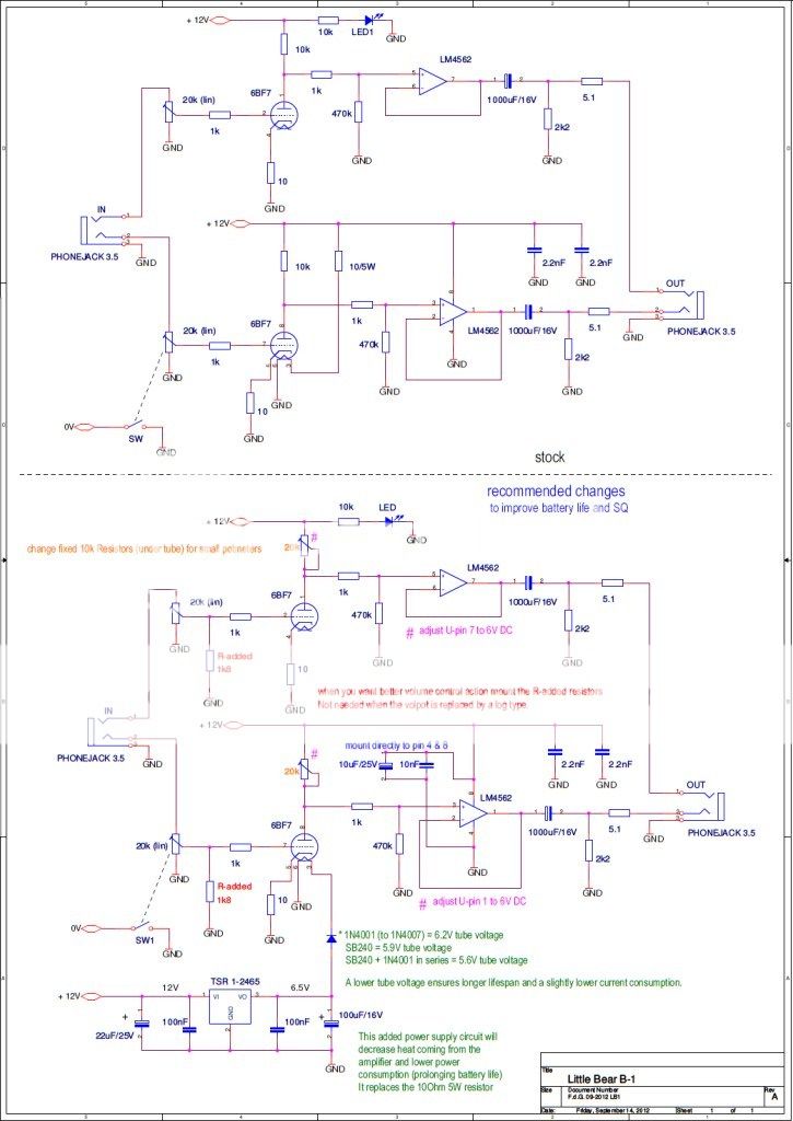
I'll have a go at those, but I need to order the parts. The electrolytics are fair enough in the regulator circuit and on the chip (does it really need 35v?) - but what do you recommend for the other 3 caps (100nF x 2 and 10nF x 1) - there are so many types! 16V is enough. In my stock I only carry 35V and 50V for 10uF. Higher voltage ratings usually translates to longer life. The caps I would use ceramic multilayer Z5U will already do. When you are afraid it will affect the sound (it will in that case) use the film type ones. There are no fast circuits needing real HF decoupling that only ceramics will bring, so film types will do just as good in this case, they are more expensive though. 1. I have fitted a log pot - the original pot was too scratchy. Of course it isn't optimised for this circuit - I assume the 1k8 mod won't work for the log pot? Indeed the 1k8 is to sortof 'approximate' a log pot using the lin pot that is installed. Not needed when a log pot is used. A log pot would be preferred as it ensures the input resistance is constant. A lin pot with the resistor has a varying input resistance (between 1.6 kOhm and 20 kOhm depending on volpot setting) 2. Should the LED in the recommended changes be also in the original drawing? I assume this is not an additional item? The LED is in the original circuit and is unchanged. In the pict of the seller you can see they changed some values. The cathode R was 9.1 and now 10 Ohm (you can even make them 0 Ohm to 100 Ohm) The LED resistor was 470 Ohm and now is 10 kOhm (now they use a high efficiency LED) The heater resistor was 22 Ohm, they made it 11 Ohm and sell it with 10 Ohm 3. What current/power will the 20k pots need to handle? 1mA, so the smallest one will already be O.K. I recommend cermet or conductive plastic 4. Can you confirm I need to revert to 10 ohms heater resistor? 22 Ohm or even 24 Ohm (27 will probably be too high) WHEN you haven't done the TSR mod. With the TSR mod the 10 Ohm (and thus also it's heat) is gone.  I'll start with the regulator mod to get the heat down as I'm getting through quite alot of shirt pockets. ;D at the same time replace those 10k resistors under the tube for 20k pots. The schematics are updated (use the pdf file link) |
|
|
|
Post by dicky on Sept 15, 2012 6:40:10 GMT
Thanks very much, Frans.  The parts are ordered. I'll update when the mods are underway.  |
|
mrarroyo
Been here a while!
Our man in Miami!
Posts: 1,003
|
Post by mrarroyo on Sept 15, 2012 12:39:13 GMT
Ok, so I need a 20-24 ohm 5 watt resistor to implement the simple mod. This simple mod should double the run time by a factor of 2 and the unit will not run as hot. Is this correct? Thanks.
|
|
|
|
Post by dicky on Sept 19, 2012 7:07:17 GMT
Hi Miguel, 24 ohms might be a bit too high as it would drop the heater voltage to about 5.2V. I'd plump for 20ohms. It does run cooler but I can't vouch for doubling the play time.
|
|
|
|
Post by dicky on Sept 19, 2012 7:08:25 GMT
I've got all the bits now to do Frans' mods, but I won't get a chance to do them until the weekend. I'll post back here when they're done.
|
|
mrarroyo
Been here a while!
Our man in Miami!
Posts: 1,003
|
Post by mrarroyo on Sept 19, 2012 9:34:45 GMT
|
|
Deleted
Deleted Member
Posts: 0
|
Post by Deleted on Sept 19, 2012 10:17:40 GMT
Miguel
When using a tube with a 6.3V heater at 300mA, a 2W resistor
will be close to it's maximum ratings and will be quite hot.
Alex
|
|
Deleted
Deleted Member
Posts: 0
|
Post by Deleted on Sept 19, 2012 10:25:41 GMT
Alex is correct... it will dissipate 1.8W so close to it's limit and will be hot.
Since you will be buying 10 of those (in a pack) and IF there is enough space you can divide the 1.8W over 4 resistors thus each dissipating 0.45W.
To do this you parrallel 2 resistors and make another pair of 2 resistors in parallel and mount those 2 sets of parrallel resistors in series.
This will substitute the resistor, effectively creating a 20 Ohm/8W resistor.
The amp itself will still be hot and still draw 3.6W (with a 10 Ohm it draws 4.8W) so you will gain 30% playing time.
SQ may degrade a bit but this can be corrected by placing 2 small 20k pots instead of the fixed 10k resistors under the tube and simply 'adjust' the operation point to the correct value.
|
|
Deleted
Deleted Member
Posts: 0
|
Post by Deleted on Sept 19, 2012 10:40:47 GMT
A 1N5339B 5.6V 5W Zener diode could be nice there if readily available ?
|
|
Deleted
Deleted Member
Posts: 0
|
Post by Deleted on Sept 19, 2012 10:45:08 GMT
or a 1N5341B 6.2V/5W zener diode. You should realise that when accidentally connecting this diode the wrong way around you would end up with 11V on the 6.3V heater... It will light up quite bright for a short period.  |
|
Deleted
Deleted Member
Posts: 0
|
Post by Deleted on Sept 19, 2012 10:51:42 GMT
;D Sorry Frans. I forgot for a moment it was Miguel we were advising . P.S.
All in good fun my friend |
|
mrarroyo
Been here a while!
Our man in Miami!
Posts: 1,003
|
Post by mrarroyo on Sept 19, 2012 22:30:39 GMT
That is right, keep it simple people.
|
|
Deleted
Deleted Member
Posts: 0
|
Post by Deleted on Sept 19, 2012 22:45:33 GMT
That is right, keep it simple people. What could be simpler than fitting a 5W Zener diode instead of a resistor, with the marked "bar" side of the Zener connecting to the +VE side of the +12V supply ? (unlike a normal diode) Even with compatible 6.3V filament tubes having different heater currents,(even up to say 800mA ), the filament would still be getting the same voltage within fairly close tolerances. The drawback is that they are more expensive, and you will not be able to get them at your local Ratshack store. |
|
mrarroyo
Been here a while!
Our man in Miami!
Posts: 1,003
|
Post by mrarroyo on Sept 20, 2012 10:16:47 GMT
Ok, show me a picture of the before and after.
|
|
Deleted
Deleted Member
Posts: 0
|
Post by Deleted on Sept 20, 2012 13:13:32 GMT
I will paint you a picture of 'real life' values with 10 Ohm, 20 Ohm, 5.6V zener, 6.2V zener, TSR mod Battery voltages will vary from 13.8V (freshly charged) to 10V (near end of charge). what will happen.. 10 Ohm voltage over tube @ 13.8V = 9.2V 12V = 8V 10V = 6.7V (they probably want to sell owners some more tubes) 20 Ohm voltage over tube @ 13.8V = 6.9V 12V = 6V 10V = 5V (usable tube voltage range) 5.6V zener voltage over tube @ 13.8V = 8.2V (hmm a bit high) 12V = 6.2V 10V = 4.4V (hmm a bit low) 6.2V zener voltage over tube @ 13.8V = 7.6V (a tad too high) 12V = 5.8V 10V = 3.8V (way too low) so with zeners the heater (and thus emission and operating point) varies 3.8V With 10 Ohm the heater varies 2.5V (so more stable) With 20 Ohm the heater varies 1.9V (so even more stable) A no-brainer... the 20 Ohm wins. Oh wait even better... TSR mod 9V-14.4 Vinput always 6.2V on the heater and lowest power consumption and least heat dissipation. Pick your poision.  |
|
mrarroyo
Been here a while!
Our man in Miami!
Posts: 1,003
|
Post by mrarroyo on Sept 21, 2012 9:42:17 GMT
20 ohm 5 watt resistor it is, plus easier for yours truly to install.
|
|
|
|
Post by dicky on Sept 23, 2012 9:07:33 GMT
Hi Folks, I've done Fran's mods and it's kinda working. It's playing music.  But, I can't adjust the voltage at pin 1 on the chip to 6v - it remains at a constant 11.04v. Pin 7 is adjusted to 6.00v. Another problem I have is that the volume control (20k log) is no good (NOT A RESULT OF FRANS' MODS - IT WAS LIKE THIS BEFORE). As soon as I switch on I have too much volume - it starts loud and only gets louder! I have to use the volume control on my iPod to adjust it to comfortable levels. Otherwise it seems to sound fine and I'm no longer getting radiation burns from the valve. I'm reluctant to leave it on too long though in case the pin 1 voltage causes damage. I've attached some piccies (hopefully) - maybe a grown-up can see why I can't adjust pin 1 voltage? The pot seems to be working OK - i.e. the resistance changes when I adjust it.  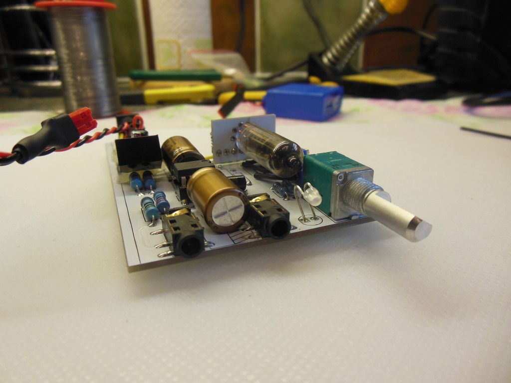 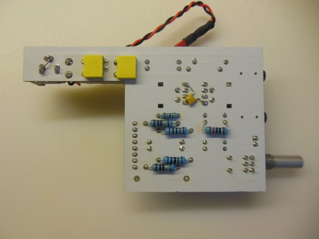 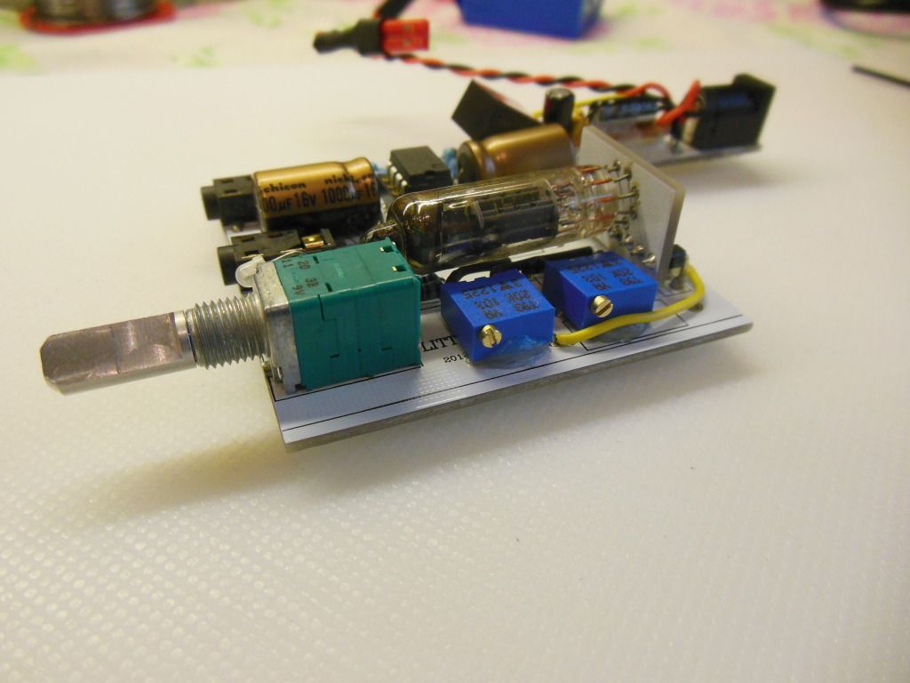 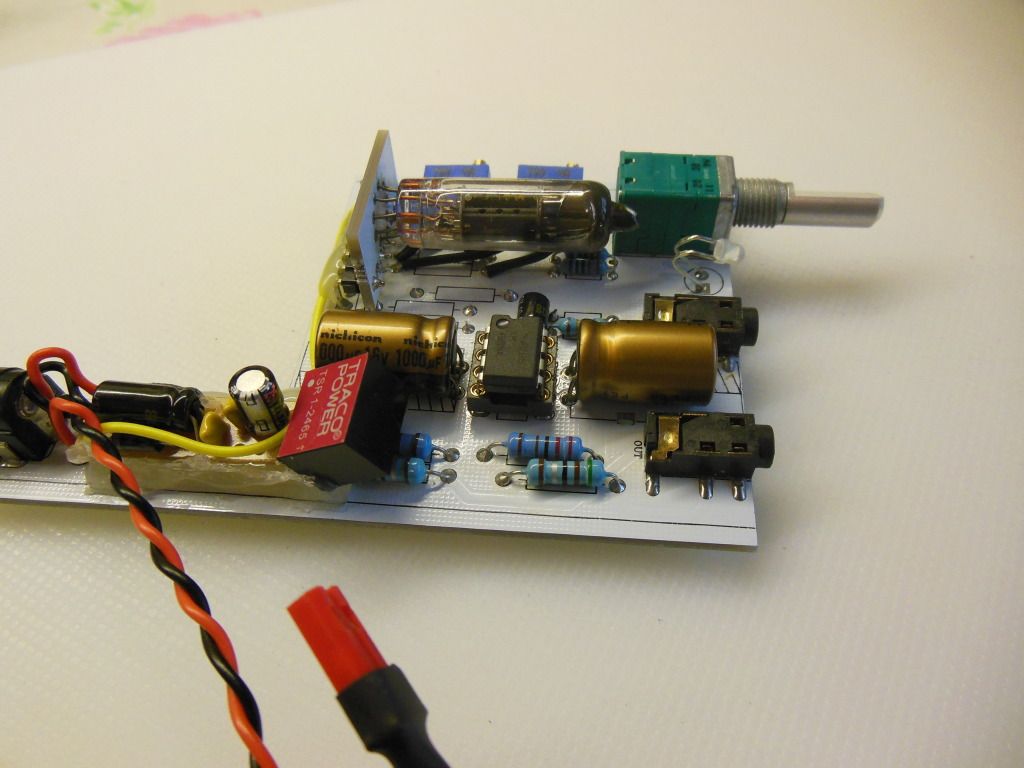 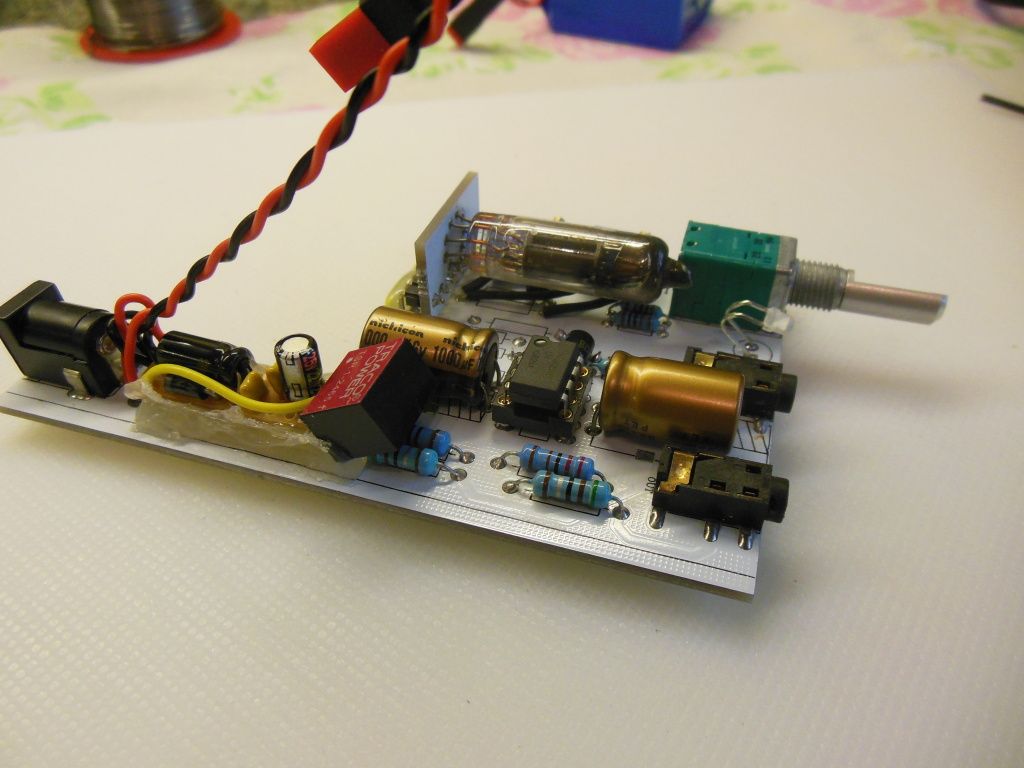 |
|
|
|
Post by dicky on Sept 23, 2012 9:10:09 GMT
I should mention I moved the original resistors and caps to the underside to make room for the extra bits-and-bobs. it's a bit tight in there!  |
|