elysion
Been here a while!  Team Anti M$ AND Facebook.
contra torrentem
Team Anti M$ AND Facebook.
contra torrentem
Posts: 2,375
|
Post by elysion on Jul 11, 2012 3:26:37 GMT
Hi guys, as mentioned somewhere in "saucerful" about a month ago, I've done my first soldering steps. Last evening, step two has followed. I've started my first simple soldering project. It's a simple kit from Conrad electronics: A mono amp for use with a parabolic microphone. I've did it at a computer club under the guidance of a guy that is extremely experienced with electronics. His work for his employer consists mostly of SMD soldering. The soldering is completely done by me, but he has helped me when I had questions and he had also an eye on my solder joints. The project isn't finished entirely. I had to go because I needed to catch the last train. The work was done in about one and a half hour. The rest will be done soon and won't be much additional work. I still can't solder at home, but that's only because I don't have a few needed items. I really need good leaded silver-loaded solder. I have already lead free silver-loaded solder at home, but that's only for situations when it won't be a good idea to mix leaded and unleaded solder. My intention is to use leaded solder for almost everything. The problem is that I can only get standard Sn60Pb40 solder (from Stannol for example). I'll drop a line to Mike soon. I hope he can help me with that. I also search components for a small stock of electronic parts for further experiments (like good caps etc.). I did not try the lead free silver-loaded solder so far, but it is rather interesting since it should be a good quality lead free solder (containing also Ag and Ge for better results). The added Germanium should give this solder a surface that is almost as shining as leaded solder and they promise it's close in handling to leaded solder. I've bought that solder only for having some lead free solder around. AFAIK, the solder we have used in the computer club is standard Sn60Pb40 (don't know the source and the details though). Now here are the pics. Sorry for the rather bad quality, but I did take them during the night in my apartment and I've had to use an unusual camera setting to get rid of too much reflections from the flash. 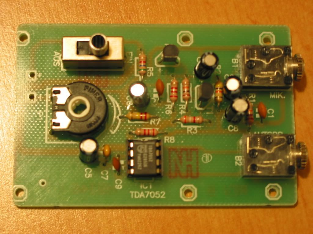 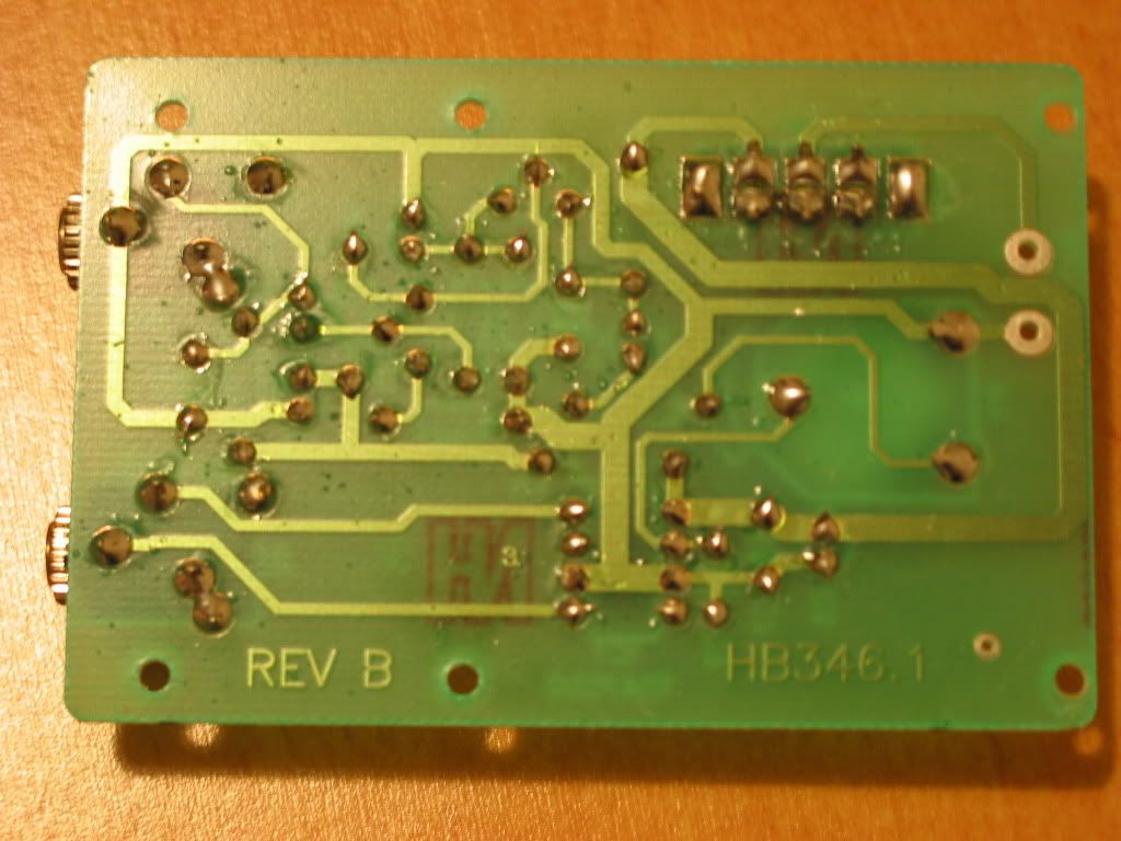 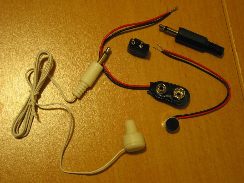 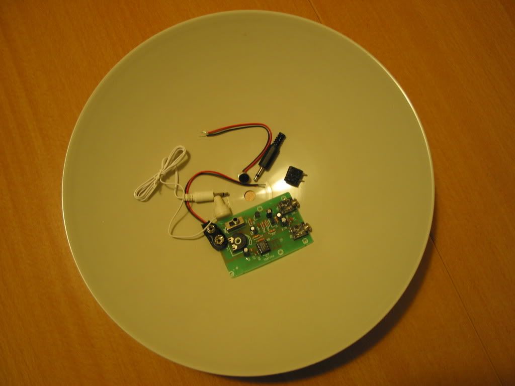 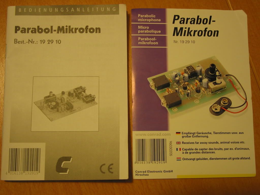 |
|
elysion
Been here a while!
Team Anti M$ AND Facebook.
contra torrentem
Posts: 2,375
|
Post by elysion on Jul 11, 2012 3:28:19 GMT
BTW: It's a really great feeling to have done the first few steps. I can't wait for the next steps.   |
|
Spirit
Been here a while!
That's where I'm gonna go when I die
Posts: 1,107
|
Post by Spirit on Jul 11, 2012 6:25:26 GMT
Looking good mate! Certainly better than my first few efforts |
|
XTRProf
Fully Modded
Pssst ! Got any spare capacitors ?
Posts: 5,689
|
Post by XTRProf on Jul 11, 2012 6:30:32 GMT
Good work there! Enjoying diy dac and amp coming soon, it seems.  Also, clean up the flux with some flux remover or alcohol for a more professional jobby. Btw, why do you go for a parabolic microphone? Eardrop on somebody in a secret service way?  You joining the Swiss Secret Service (SSS  , Heil, Hitler!) soon? On a serious note, what's the name of the Swiss secret service? A condenser mic amp with phantom PS will be a better project, IMVHO. Alright, alright, this is your first let the fingers do the walking project. I concede ...........  |
|
Deleted
Deleted Member
Posts: 0
|
Post by Deleted on Jul 11, 2012 8:25:45 GMT
Soldering isn't good for me!!
I'm just too ocd about everything. I think that's why I work in a barmy business.
I had to solder a wire on one of my helicopters and the joint was so tiny that it was daft trying to get it on to the board. (The 'board' is only one and a half inches square) So, I split the wire and the negative stayed where it was already fixed and I fixed the positive on to the other side of the board where there was more room .......
But I HATED the fact that I had to bodge it like that to make the heli work and felt very uncomfortable with it!!
|
|
Deleted
Deleted Member
Posts: 0
|
Post by Deleted on Jul 11, 2012 15:53:59 GMT
All looking good Christian. Don't forget you can always touch up your piccys, no need to apologise  Attachments:
|
|
elysion
Been here a while!
Team Anti M$ AND Facebook.
contra torrentem
Posts: 2,375
|
Post by elysion on Jul 11, 2012 21:47:01 GMT
I have IPA around and I was also thinking about cleaning the PCB. But I'll do it, when it's finished. I've got the kit from my brother long ago. He had bought it from Conrad, but never had the time to do the work. I've chosen this kit since I had it around and because it won't matter at all if I'd damage it or if it won't work in the end. So it's a good kit for first soldering trials. en.wikipedia.org/wiki/Swiss_intelligence_agenciesIt was very late and I was not in the mood to alter the pics in Photoshop or GIMP. I'll take the photos usually in a manner that doesn't need additional image processing. BTW: The hardest part was the on/off switch since the holes on the PCB are very big there. I've had to use a lot of solder to fill the gaps and this with a rather small solder tip. But it was almost perfect for the small holes. Almost no problems there. The on/off switch also got VERY hot, but (fortunately) this part takes a lot of heat without damage. No heat problems with the other parts though. According to the manual of the kit, especially the transistors are prone to heat damage, but it was easy to fit them. The electrolytic capacitors in this kit are nothing special, but I was a bit suprised to see only 105 degree Celsius types, only with the exception of one cap that was a 85 degree Celsius type. The PCB seems to be a rather good quality it was a lot easier to solder with this PCB than with the broken PSU PCB which I've repaired a month ago. I've had to redo 3-4 solder joints which have been not good enough and desoldering was also easy. A month ago, I've used only desolder wick, yesterday I've used mostly a desolder pump. |
|
elysion
Been here a while!
Team Anti M$ AND Facebook.
contra torrentem
Posts: 2,375
|
Post by elysion on Jul 11, 2012 22:02:25 GMT
Since I have some aluminum spray around, I'm thinking of spraying the parabolic dish. I'd have to buy a clear paint spray though to protect the aluminum surface.
I've used the aluminum spray last year to create a (rather primitive) shielding for the cases of my Behringer UCA222 USB DACs. To my suprise, the aluminum surface seems to be rather good in terms of electrical conductivity. Since the parabolic dish is used here only for sonic waves, I guess it won't make a difference at all. But it will enhance the look.
I have still no idea how to affix the parabolic micrphone to the dish. But in the end, it doesn't matter a lot. It's only an exercise and I'm already happy if the PCB with the mono amp works. The only real purpose for this kit is the soldering practice it gives me.
I have already a few ideas for the next steps. I have some unmodded amps around and some headphones would like a recabling. I have already some Neutrik plugs for recabling.
Last summer, I've bought also two kits for a FM signal generator. I'll do them after I have enough experience with soldering. Probably, I'll replace some of the components in the kit with better quality parts.
|
|
XTRProf
Fully Modded
Pssst ! Got any spare capacitors ?
Posts: 5,689
|
Post by XTRProf on Jul 13, 2012 4:36:01 GMT
I have still no idea how to affix the parabolic micrphone to the dish. Are you sure you are not missing any parts there? The mic module must be with an adapter of the size as the internal diameter of the parabolic disc. |
|
elysion
Been here a while!
Team Anti M$ AND Facebook.
contra torrentem
Posts: 2,375
|
Post by elysion on Jul 13, 2012 5:45:50 GMT
The mic has exactly the size of the hole in the dish. Of couse, it will be tricky to affix it there.
To be honest: I don't know how "complete" this kit is. I don't think the kit respectively the end result will have much use for me beside beeing a good soldering exercise. At least the knob for the pot IS missing, but it was really not in the shrink-wrap with the other components.
I've got the kit years ago from my brother and it was simply lying around. Excellent for first soldering practice, but almost no use in practice.
At least, it wouldn't be a problem if anything goes wrong.
|
|
Deleted
Deleted Member
Posts: 0
|
Post by Deleted on Jul 13, 2012 5:54:32 GMT
In other implementations I have seen, they aren't mounted there, but suspended in front of the centre hole to focus the sound.
Alex
|
|
elysion
Been here a while!
Team Anti M$ AND Facebook.
contra torrentem
Posts: 2,375
|
Post by elysion on Jul 13, 2012 6:36:43 GMT
The strange thing is: The dish isn't mentioned in the manual at all. It's a strange kit or my brother gave not everything he had to me. The kit is at least ten years old. It was lying around several years in the workshop of my brother and after that he gave it to me. I had also no use for it and it was lying around again. I'm already happy if the PCB is working an I have an normal Sennheiser mono mic around for testing. The parabolic dish/mic is only a bonus. Since the hole in the dish has exactly the dimensions of the mic, I guess it intended to be affixed there. But almost any satellite dishes have their receivers in front the the dish. |
|
elysion
Been here a while!
Team Anti M$ AND Facebook.
contra torrentem
Posts: 2,375
|
Post by elysion on Jul 13, 2012 6:40:37 GMT
I wrote a mail to Mike yesterday. I hope he can send my a couple of rolls with good solder. As soon as I have good leaded solder, I'd like to finish the work and go for the next step.
I have a lot of plans at the moment. I have the four crossfeed PCB from Frans on the table near me for example. This babes had to wait a long time.
|
|
XTRProf
Fully Modded
Pssst ! Got any spare capacitors ?
Posts: 5,689
|
Post by XTRProf on Jul 13, 2012 6:51:39 GMT
I have the four crossfeed PCB from Frans on the table near me for example. Sorry, what are those?  |
|
elysion
Been here a while!
Team Anti M$ AND Facebook.
contra torrentem
Posts: 2,375
|
Post by elysion on Jul 13, 2012 6:58:12 GMT
It's quite long ago: Frans has made some headphone x-feed PCB's that can be populated in three different configurations. I've bought four of them back then. We have a thread about them somewhere. I'll have to search it anyway soon, since I'll need the information from the thread (circuit diagram).
|
|
Will
Been here a while!
Ribena abuser!
Member since 2008
Posts: 2,164
|
Post by Will on Jul 13, 2012 21:20:26 GMT
Nicely done Christian! Very tidy for your first project.
|
|
elysion
Been here a while!
Team Anti M$ AND Facebook.
contra torrentem
Posts: 2,375
|
Post by elysion on Jul 13, 2012 21:27:57 GMT
I guess that I already know why it was rather easy even at the beginning: They had a good regulated solder station at the computer club.
My own solder station is also regulated, but I can't use it unless I have got the leaded solder that I want.
I've had an unregulated solder iron in my hands a few years ago. It was really a pain and almost impossible to make a good solder joint. With regulation and the right temperature, everything goes better.
The right size for the solder tip is also important IMO. This time, it was a small solder tip, just the right size for most of the solder joints. I've had only problems with the big holes in the PCB (where the on/off switch is).
|
|
XTRProf
Fully Modded
Pssst ! Got any spare capacitors ?
Posts: 5,689
|
Post by XTRProf on Jul 13, 2012 23:19:00 GMT
Actually, regulated or not soldering iron, it's about the same when you know how to use the iron. Btw, for unregulated, you can also control temperature by a wiping pad with water. I only use it to clean the tip when it's messy and not to regulate. Every thing will be good again after cleaning the tip.
|
|
Deleted
Deleted Member
Posts: 0
|
Post by Deleted on Jul 13, 2012 23:56:27 GMT
Unless you have been trying to desolder components on a PCB that used bloody lead free solder !  |
|
XTRProf
Fully Modded
Pssst ! Got any spare capacitors ?
Posts: 5,689
|
Post by XTRProf on Jul 14, 2012 0:40:43 GMT
Unless you have been trying to desolder components on a PCB that used bloody lead free solder ! Actually, the temperature control is more for controlling overheating to components. We use lots of Werners, I think as faint memory now after more than 20 years away, when I was in the PCBA plant. Also, we can't have many overheated damage components thru bad soldering skill from the operators, right? Who will account for the low yield and large overheated scrap components to the top management every week? Me and the engineers and not the operstors, of course.  I can tell you some of those bloody top management were not friendly at all as they were put in charge of bottom line to the share holders. |
|
Deleted
Deleted Member
Posts: 0
|
Post by Deleted on Jul 14, 2012 0:54:12 GMT
Chong
I am not talking about temperature. I am talking about the resulting damage from ROHS solder to soldering iron tips and heated solder suckers contact area.They go dark looking and lose heat transfer capabilities.
Alex
|
|
XTRProf
Fully Modded
Pssst ! Got any spare capacitors ?
Posts: 5,689
|
Post by XTRProf on Jul 14, 2012 1:10:20 GMT
I am not talking about temperature. I am talking about the resulting damage from ROHS solder to soldering iron tips and heated solder suckers contact area.They go dark looking and lose heat transfer capabilities. A thousand apologies! Er, the rosin flux content also affects. Also, wipe the tip more frequently if bad. So far, I have been using NOS Wonder Solder ROHS. It is obviously not the same anymore when compared to leaded. But current ROHS solder seems to have improved. Try latest Cardas solder. |
|
elysion
Been here a while!
Team Anti M$ AND Facebook.
contra torrentem
Posts: 2,375
|
Post by elysion on Jul 14, 2012 3:58:35 GMT
I've bought quite a few solder tips for my soldering station. They are not the best (I know) but they are cheap and if needed, there are reports that Weller tips also would fit. My intention is to use one solder tip only for desoldering RoHS solder. For repopuluation of the PCB, I guess it would be a good idea to use a different tip. That's also the reason why I have bought a small quantity of RoHS solder (with added Ag and Ge for better results). I hope Mike is responding soon to my mail (asking for buying solder from him). Otherwise, I'll have to go for standard leaded solder (without Ag content). Damn, I can't wait. I WANT to solder NOW! |
|
elysion
Been here a while!
Team Anti M$ AND Facebook.
contra torrentem
Posts: 2,375
|
Post by elysion on Jul 14, 2012 4:02:34 GMT
There's also a second reason for the acceptable results with my first soldering tests: I had very good advice from an expert. Soldering is his profession. He told me more than once to rework some solder joints because they've been not perfect. This way, I got also more practice in desoldering. Personally, he's mostly using desolder wick, but I must admit that I prefer the desolder pump often. Sometimes, the desolder wick is the better option though.
I feel also better with small soldering tips, but that's probabably only a matter of the intended "target". Small tips for small pads, big tips for big ones.
|
|
Deleted
Deleted Member
Posts: 0
|
Post by Deleted on Jul 14, 2012 4:51:20 GMT
Christian
The key here is to ensure that the components leads are nice and clean beforehand, and to use the appropriate temperature for the job.
In my 44 years with Telstra , as well as a long term hobbyist, I have never felt the need for anything more than good quality 60/40 Resin core solder.The thickness of the solder used should also be appropiate for the job. If it's just I.C.s and small components, use a small gauge solder.I would have done 10s of 1,000s of solder joints in that time, as well as teaching staff under my control.
Regards
Alex
|
|


 Also, clean up the flux with some flux remover or alcohol for a more professional jobby.
 You joining the Swiss Secret Service (SSS
  , Heil, Hitler!) soon? On a serious note, what's the name of the Swiss secret service? A condenser mic amp with phantom PS will be a better project, IMVHO.


 I can tell you some of those bloody top management were not friendly at all as they were put in charge of bottom line to the share holders.