|
|
Post by PinkFloyd on Feb 6, 2010 22:24:53 GMT
Just checked the bias on the Bravo amp and it was pretty way out measuring 12.1V Right channel and 13.2 left channel  They obviously don't precision bias at the factory (probably too time consuming to do each one and they just set the trimpots to midway)  Soooo..... had a quick look at the circuit and changed the bias to the recommended 16.5V both channels. I thought this amp sounded good before adjusting the bias but now it sounds REALLY good! Adjusting the bias is SIMPLE folks, don't be put off, here's how to do it.... I have made the instructions as simple as possible: There are two yellow trimpots (LTP and RTP) for tuning the DC bias voltage of each channel. After the valves have been running for a long period ( a few months) or after changing to a new valve the it will be necessary to re calibrate the bias. For this operation you will need a small screwdriver and a multimeter set to the 20V DC range. 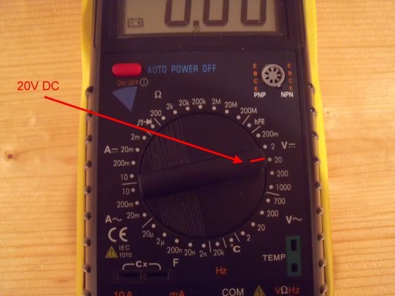 1. Power ON the amp with no audio signal input. Ensure that the Valve is fitted. 3. Wait at least 5 minutes for the amp to heat up. 4. Use the multi-meter to detect the DC voltage between the test point L220 on the PCB and GND. (ie: probe between L220 and GND) 5. If it needs adjusting turn the screw on the top of the LTP trimpot with a small screwdriver (clockwise or anticlockwise) until the voltage is as close to +16.5V as possible. 6. Then, repeat step 4 and 5 for the other channel. 7. Leave the amp on for a further 30 minutes and re-check / adjust. Job done! 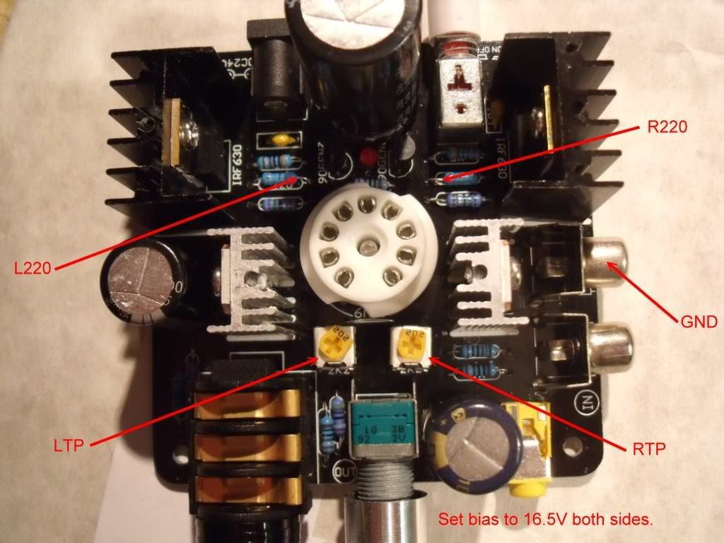 Valve removed for illustration purposes only... always ensure valve is fitted when performing a re-bias. Hope this helps  |
|
Deleted
Deleted Member
Posts: 0
|
Post by Deleted on Apr 2, 2010 13:06:27 GMT
Hey, PinkFloyd: Thanks for posting the bias adjustment photos! I am new to this forum, need some advice on this, and would appreciate any help. I just received from Hong Kong two BRAVO V2 amps with the 12AU7 tubes, and neither of them have the TRIM POTS you show in your photo. Instead they have fixed value resistors installed. Is it possible for me to replace the fixed value resistors with trim pots, and can you offer a suggestion as to the type of trim pots to use (since they have to withstand heat)? Do you also know of a source that I can order them from? My soldering skills are pretty good, so I am not afraid to tinker.  TIA for your response! |
|
|
|
Post by oohms on Apr 2, 2010 14:06:52 GMT
The cathode in the 12AU7 version is connected to ground, so theres no resistor to adjust. They end up being biased at between 11-13 volts  |
|
Deleted
Deleted Member
Posts: 0
|
Post by Deleted on Apr 2, 2010 15:02:45 GMT
Thanks, oohms!
So, am I stuck with this design, or can I modify it by adding trim pots to enable bias adjustment?
|
|
|
|
Post by oohms on Apr 2, 2010 15:42:08 GMT
There are other mods you can do, the best one would be to replace the mosfet for something like IRF510 (opens up the high end), buying some tubes on ebay (there are small differences), power supply upgrades etc. But apart from the lack of bias adjustment it is pretty much the same as all the other G1 amps
edit: after i figure out the neatest way to do the schematic for it, i should make a new thread for the 12AU7 version
|
|
Deleted
Deleted Member
Posts: 0
|
Post by Deleted on Apr 2, 2010 16:13:14 GMT
Thanks again, oohms!
I look forward to the new thread with the schematic. And, perhaps some photos?
All the Best!
|
|
|
|
Post by oohms on Apr 5, 2010 15:29:48 GMT
|
|
|
|
Post by upsound on Apr 15, 2010 16:46:15 GMT
saw the upgrade to the V2 unit for bias adj...could work for the V1 also. there is a much cleaner change or mod when you actually add wires/leads to the bottom so as not to be removing everything all the time/ as shown by a member in one of the forums - the V2 has small holes in it/bottom plexi - for this proceedure..... also why not move the newer/larger 2200uf 16 volt caps more to the outside and back to better protect from high heat of the mosfets and sinks..... a littel dab of glue is needed to seat the larger cap but much better in lower heat transfer...? you would be surprised what 1 mm will do in lowering an operating temp.....
|
|
|
|
Post by stevebol on Sept 12, 2010 9:15:43 GMT
Thanks for this.
Are these voltages the same for the G1 and G2 Indeeds?
|
|
Deleted
Deleted Member
Posts: 0
|
Post by Deleted on Sept 12, 2010 9:55:34 GMT
the voltages are the same for all of these amps under the following conditions. If your amp still is in stock form or has IRFxxx MOSFETS in it (stock = IRFxxx) then adjust bias to 15.5 V (doesn't need to be exact anything between 15 and 16V is O.K.) If the amp has been modified with IRLxxx type MOSFET's adjust bias to 13.5V (somewhere between 13 and 14V is O.K.) In all cases this would result in 11.5V on the + side of the 1000uF/25V output capacitors. This will give the maximum and symmetrical voltage swing of around 12 Vpp (around 4Veff) into 300 Ohms (around 50mW) for all amps and around 2V eff in 32 Ohms (= 125mW, slightly more for G2 and less for all other versions) When IRL are fitted instead of IRF you gain some more headroom which equates to about 50% increase in output power. Should you want to decrease the crosstalk (if it still bothers you on loud volumes at the recommended anode voltage settings) you might want to adjust for 16.5V with IRF fitted and 14.5V with IRL fitted. (Mike adjusted his by ear and came to 16.5V also) The LM317's on the small cooling fins next to the tube will get much hotter though. Stock these amps are adjusted near 12V insuring colder running LM317's but also having more crosstalk distortion. The proper adjustment of the bias voltage makes quite some noticeable improvements.  |
|
|
|
Post by stevebol on Sept 13, 2010 0:39:59 GMT
Thanks solderdude, and to everyone else who has spent considerable time on this. I have an Indeed G2 and a Little Dot MK III on the way so I read the entire 798 reply thread last night on this. For those of us that are electronically challenged we may only attempt minor mods, if any, but the bias adjust seems to be one in particular that should be done.
AFAIK the new G2 comes with the newer Mosfets.
Thanks again.
|
|
|
|
Post by vfrboy01 on Dec 16, 2010 12:50:33 GMT
Hello I discovered this forum yesterday and I have had an indeed headphone amp for almost a year. My amp is an indeed G1 I think and the board looks a little different from the one shown in this guide. I have taken a picture of my amp, (sorry the picture is bad I used my phone). Could someone explain where on my board I should measure the voltage please?  I tried to measure from each of the two single resistors on my board (where there are three on the board in the original guide) to ground and got 24.37v from both so maybe I need to check from somewhere else ? Sorry new to this electricity stuff so please excuse errors . Thanks for your help Steve |
|
Deleted
Deleted Member
Posts: 0
|
Post by Deleted on Dec 16, 2010 20:05:06 GMT
voltmeter in DC volt setting.
black lead on RCA shield (ground)
red lead on + of 1000uF capacitor (there are 2 one for each channel)
adjust the voltage on that point to 12.5V or somewhere around it.
This gives about 16.5V on the anode.
Now adjust the other channel with the other pot and measuring on the other capacitor.
You might have to readjust the first channel after that.
check voltages again about 15 mins later and readjust again.
After that leave it where it is.
|
|
|
|
Post by vfrboy01 on Dec 17, 2010 12:17:48 GMT
Thanks so much for the info ..... This is fun |
|
|
|
Post by vfrboy01 on Dec 17, 2010 13:35:25 GMT
Checked the voltages as per instructions and with a Jan Phillips 6922 I just got I can only get 7.06 on left with the pot turned full. The right is fine with 12.5 with the other pot turned about 1/2 way ... I can hear sound from both channels ( and it sounds pretty good) but does this mean the valve is faulty?. I tried another valve and I can balance the voltages just fine. Thanks Steve |
|
|
|
Post by vfrboy01 on Dec 20, 2010 18:07:38 GMT
Got another Jan Philips valve, this one was supposed to have been checked at the store, but with the pots turned to max I can only get 8.31 v on left and 11.46 v or the right. What do I do, balance the voltages to the same value as high as I can or is there something wrong with the valve ? Any help much appreciated ... Steve |
|
Deleted
Deleted Member
Posts: 0
|
Post by Deleted on Dec 20, 2010 18:28:20 GMT
In fact the Philips are a bit too good.
the emission on 1 tube half is more then 'expected'.
You could try to replace the 2k pots for 5k or even 10k pots.
I do recommend to mount bypass capacitors in this case over the pots.
|
|
|
|
Post by tacoboy on Apr 18, 2011 18:49:17 GMT
I have a Muse 6922EH, would it also work best at the recommended 16.5 V?
|
|
Deleted
Deleted Member
Posts: 0
|
Post by Deleted on Apr 18, 2011 19:14:17 GMT
15.5V on the anode if IRFxxx MOSFETs are used
13.5V on the anode if IRLxxx MOSFETs are used
This voltage is set so a sinewave clips at symmetrical and is the same for all tubes.
It guarantees maximum output voltage (with IRL this will be bigger then if IRF are used.
|
|
|
|
Post by tacoboy on Apr 18, 2011 19:19:04 GMT
I have the IRF630s, so set to 16.5V
|
|
Deleted
Deleted Member
Posts: 0
|
Post by Deleted on Apr 18, 2011 19:27:14 GMT
15.5 Volts I recommend
|
|
|
|
Post by tacoboy on Apr 18, 2011 20:11:40 GMT
Ooops, now set to 15.5V
|
|
|
|
Post by sartorio on May 8, 2011 19:28:56 GMT
Hi solderdude, I just received a Muse MKII with the 6N11 and stock IRF630... now I get 22.5V on left channel (18.5V on the cap), and no way to pull it down with the pot, right channel it's fine...
Thanks for any help you can give me!
Sart
|
|
Deleted
Deleted Member
Posts: 0
|
Post by Deleted on May 8, 2011 20:38:41 GMT
Hi Sart,
The Muse MkII is similar to a G2.
It is possible the heater switch (6V-12V) is not positioned correctly.
Check if you can see BOTH tube halves glowing.
If the heater is O.K....
Try to solder a wire between the 2 cathodes of the tube and see if you hear something on both outputs.
This is to determine where the fault is.
If both channels now sound similar the fault may be in the cathode pot that might be open circuit.
Should none of these tips help P.M. me.
|
|
|
|
Post by tacoboy on May 16, 2011 0:23:15 GMT
voltmeter in DC volt setting. black lead on RCA shield (ground) red lead on + of 1000uF capacitor (there are 2 one for each channel) adjust the voltage on that point to 12.5V or somewhere around it. This gives about 16.5V on the anode. Now adjust the other channel with the other pot and measuring on the other capacitor. You might have to readjust the first channel after that. check voltages again about 15 mins later and readjust again. After that leave it where it is. I have the Indeed MK2 Class A hybrid tube headphone amp. 6922EH, how do I identify the 1000uF capacitor? Edit, I think I just figured out what the capacitor looks like. Would still like to figure out the location of the L220 & R220. |
|


 They obviously don't precision bias at the factory (probably too time consuming to do each one and they just set the trimpots to midway)


