Will
Been here a while!  Ribena abuser!
Member since 2008
Posts: 2,164
|
Post by Will on May 20, 2009 17:51:57 GMT
Alex, Yes, I did that as well, in-line with what I learnt when you mentioned the modification to the JLH PSRR, and matching the resistors to the BC550's. All good stuff! I've put this diagram together for the Class A, hopefully to further help anyone building the SC Class A. Any mistakes, please let me know! This layout is for anyone who is going to use the DC offset corrector. Perhaps someone else can modify it to show "what goes where" if you don't use it. This layout does not currently show the LTP thermal modification. Once I get confirmation that the changes I have made are correct, I'll update it to show the modification. 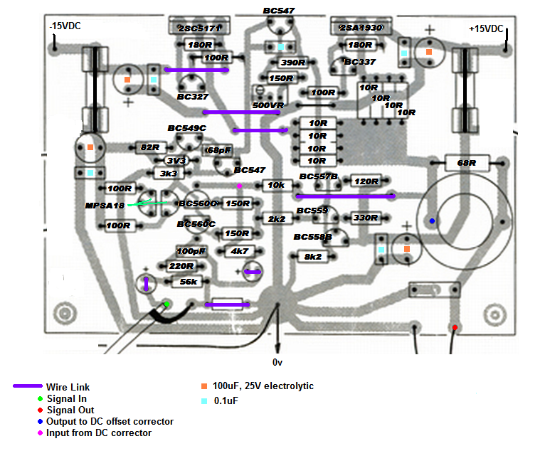 Hope it helps! |
|
Deleted
Deleted Member
Posts: 0
|
Post by Deleted on May 21, 2009 5:27:19 GMT
Will
As far as I can tell, there are no errors.
Alex
|
|
Will
Been here a while!  Ribena abuser!
Member since 2008
Posts: 2,164
|
Post by Will on May 22, 2009 14:59:39 GMT
Thanks for checking, Alex. OK, next request ;D In very simplistic terms, is this how the LTP thermal modification is implemented? Viewed from top of board. Spacing, etc, is a different matter. Once implemented, I'll update the artwork for the board. 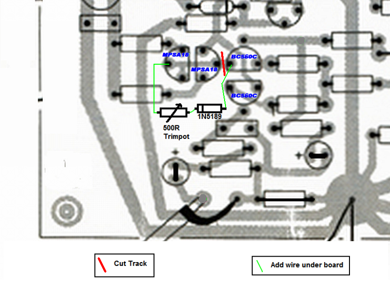 |
|
Deleted
Deleted Member
Posts: 0
|
Post by Deleted on May 22, 2009 21:27:10 GMT
Thanks for checking, Alex. OK, next request ;D In very simplistic terms, is this how the LTP thermal modification is implemented? Viewed from top of board. Spacing, etc, is a different matter. Once implemented, I'll update the artwork for the board.  Will Yes, but with a 1N5819. (just to show I did look!) Don't forget that the MPSA18 have different lead out to the original devices too. Start off with the trimpot set at around 100 ohms initially. Alex |
|
Will
Been here a while!  Ribena abuser!
Member since 2008
Posts: 2,164
|
Post by Will on May 22, 2009 22:14:22 GMT
Thanks again, Alex! Would you believe I double checked that I put the correct number? What a pillock! So, shopping list for tomorrow - 3mm nuts and bolts, glasses..  |
|
Will
Been here a while!  Ribena abuser!
Member since 2008
Posts: 2,164
|
Post by Will on Jun 1, 2009 19:56:15 GMT
|
|
Will
Been here a while!  Ribena abuser!
Member since 2008
Posts: 2,164
|
Post by Will on Jun 2, 2009 22:14:48 GMT
Connected up to a PSU, and switched on (from the far end of the room, using an extension cable, like a true coward) No pop. No magic smoke letting. Looking good. Set Bias to 100ma. Check. Measure DC offset - 4.96VDC, on each board  Cue an hour of frotting about, only to find I reversed a BC560C. Removed and replaced on both boards. Offset down to 20mV. Much better. I should explain that at this stage, I've used BC560 and MPSA18, but not matched them, as once I have these boards working, I'll be putting in the LS313/352 I have. I also have not yet implemented the LTP mod or the DC offset corrector. Connect up my alien dac and stunt headphones. oooh. Nice. For three hours. I'll leave further impressions until I've put in the LTP mod/DC offset corrector and JLH, but it is very, very nice. Even wrung a soundstage out of my Philips stunt-phones. If you are undecided about this amp, I really would suggest going for it. 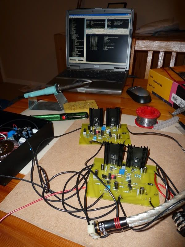 |
|
Deleted
Deleted Member
Posts: 0
|
Post by Deleted on Jun 2, 2009 22:29:36 GMT
Will
It gets MUCH better than that,after the front end balance mods and the JLH !
Alex
|
|
Will
Been here a while!  Ribena abuser!
Member since 2008
Posts: 2,164
|
Post by Will on Jun 3, 2009 6:09:58 GMT
Reposting this here, from the LS group buy thread, just in case people miss it.
Hopefully it'll help you decide to go for building this amp, if you are feeling that it is out of your reach.
-
It really is a case that If I can do it (with the help of the circuit diagram, pretty pictures and a couple of E-mails) then anyone who made the SCHA can. I'm more of a board stuffer than one of these ninjas that now which way around a cap goes, due to the closeness of the nearest transistor etc, but I am learning.
I've put up a few diagrams in the thread, that I created during my build, that have been now proven to be correct (ie my amp works!) that really should help.
The only extra 'technical bits' over the SCHA are probably the transistor matching (which is straight forward with a DMM or the circuit you (cjarchez) posted) and the board etching.
I'll be trying a method of board etching this week that Jon Clancy has tried. It is not very technical at all. A bit of etch fluid and two plastic bags! No real investment in pieces of equipment at all.
I have a post half written detailing how I etch boards. I'll post this soon, so perhaps it may encourage some to have a go, and hopefully help people make the SC Class A. If all else fails, I sure I can be persuaded to help with etching boards.. (oh jeez, did I just post that?!)
If anyone else feels that this may be a bit too technical, please post to your questions. I'm sure that they can be answered to help people feel that they can build this amp.
|
|
Deleted
Deleted Member
Posts: 0
|
Post by Deleted on Jun 3, 2009 6:25:17 GMT
Will To save people getting confused, this isn't the 15W Class A amplifier, it is the preamp/headphone amp version, which was based around the original SiliconChip 15W Class A amplifier, and uses the same PCBs, but lower power output devices and a few other changes. The LS devices as mentioned in the GB thread, may be used in both the preamp and 15W Class A amplifiers. Alex P.S. Just a reminder what Leo's rather nice build looked like. The toroidal transformer was in it's own small case.  |
|
Will
Been here a while!  Ribena abuser!
Member since 2008
Posts: 2,164
|
Post by Will on Jun 5, 2009 22:51:04 GMT
Evening all. I've implemented the LTP thermal mod, and can say that it is a definite improvement, so to that end, I've modified the original artwork for the PCB, and you can download it from here: www.mediafire.com/file/tanf2m92jhn/Class A plus thermal mod.PNG The PCB is 120mm x 81mm I've also installed the LS313/352 that I had, and they make the whole business of close matching the BC560C/MPSA18 so much easier - i.e. you dont have to!! Plenty of space left in the Group Buy, by the way ;D The trimpot is an in-line version, same as the bias trimpot. I used the Bourns 3296W for both posistions (Rapid 68-0310) I'll post pictures of the modification sometime soon. 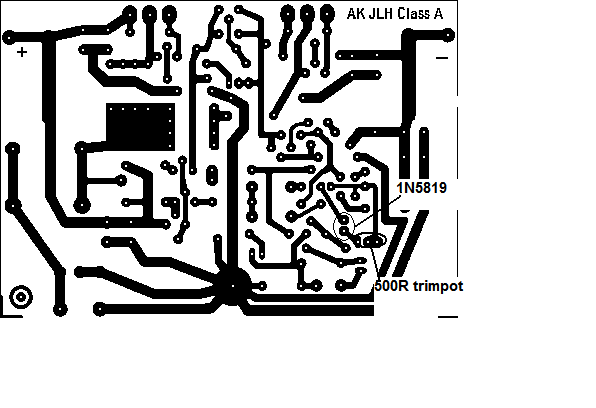 |
|
Deleted
Deleted Member
Posts: 0
|
Post by Deleted on Jun 6, 2009 0:01:55 GMT
Will Are you sure ? Some people still think that I imagine things that I claim to hear !  O.K. I should not have said that !  Nice work Will, did you have any real problem fitting the dual devices due to their different pin out ? Alex |
|
Will
Been here a while!  Ribena abuser!
Member since 2008
Posts: 2,164
|
Post by Will on Jun 6, 2009 8:26:12 GMT
The dual devices were straightforward to fit in. I used heatshrink on the emitter legs on one half of each device, and swapped legs to meet the board layout.
|
|
Will
Been here a while!  Ribena abuser!
Member since 2008
Posts: 2,164
|
Post by Will on Jun 6, 2009 19:04:06 GMT
Minor update to the layout. It now includes testpoints for the LTP thermal modification. Use them direct or with flying leads, they'll make setting the 0mv deviation easier to perform when the board is cased up.  Download. www.mediafire.com/file/zmgzzrjdmcm/Class A tpandltp.PNG board is still 120mm x 81mm I did look at moving the pads around so that you do not need to reverse legs on the BC560C/MPSA18/LS313/352, but it needed a big rejig. |
|
Will
Been here a while!  Ribena abuser!
Member since 2008
Posts: 2,164
|
Post by Will on Jun 8, 2009 20:11:02 GMT
Built up the DC offset correctors. And I really needed too, as well. I had an offset of 100mVDC, with nothing on the input, and when a pair of stuntphones was plugged in the offset dropped to 26mVDC. After fitting the offset corrector, it's now down to 6mVDC. Much better. Anyhow, the offset corrector, as detailed by Alex on page 4, is very simple to make on veroboard, but me being me, I decided to phart around with eagle, and come up with a layout. And here is the result. Robert, I see your dinosaur, and raise you lego figures   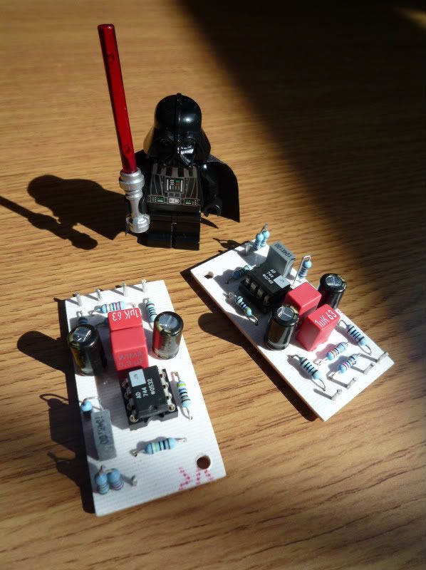 The file for etching is available here: www.mediafire.com/file/1excvmot1qn/DCoff.pngThe board is 1"x2". Nice and diddy. The schematic and layout.   Dont worry about the lack of continuity in the GND plane, it's fixed in the etch file. Pad 2 (Signal In) is taken from before the output resistor (blue dot on the diagram here rockgrotto.proboards.com/index.cgi?board=m&action=display&thread=3977&page=6#50122 and fed back into the pink spot from Pad 5 signal out. I've had a really good listen, and the amp is a wonder. I've jumped at some of the moments in the music, as the transients are stunning in speed. Music is presented in an authorative, liquid style which is very easy to listen too. I need to etch some JLH psrr's for this, but I'm a little scared about how good this amp will be after! (knowing how it transformed the SCHA) Another thing. If you have AKG K701, you owe it to yourself to make this amp. It drives them beautifully, there seems to be a nice synergy going on. Next month, Modushop.biz will be hearing from me....  |
|
Deleted
Deleted Member
Posts: 0
|
Post by Deleted on Jun 8, 2009 20:35:41 GMT
Very slick Will. The force is definitely with you!  |
|
Deleted
Deleted Member
Posts: 0
|
Post by Deleted on Jun 8, 2009 22:17:26 GMT
Will
Very nice looking little PCB. Looks lot better than my Dalo pen jobs !
Alex
|
|
leo
Been here a while!  Team wtf is it?
Posts: 3,638
|
Post by leo on Jun 9, 2009 1:02:06 GMT
Looks shite loads better than mine on vero too! nicely done Will  |
|
Spirit
Been here a while!  That's where I'm gonna go when I die
Posts: 1,107
|
Post by Spirit on Jun 9, 2009 8:21:46 GMT
Will... stop it =P
Bad influence bad.
|
|
Will
Been here a while!  Ribena abuser!
Member since 2008
Posts: 2,164
|
Post by Will on Jun 9, 2009 8:29:13 GMT
Thanks for the compliments, guys!  Love the picture, Chris. You can always build one when you come back, Phil. (your other boards are in the post) |
|
robertkd
Been here a while!  Electronics Engineer from sunny Queensland
Posts: 111
|
Post by robertkd on Jun 9, 2009 11:01:37 GMT
mmm I see your lego figures and raise you a lego model in that case   |
|
Will
Been here a while!  Ribena abuser!
Member since 2008
Posts: 2,164
|
Post by Will on Jun 9, 2009 20:20:50 GMT
Hmmm, I can see this escalating if we're not careful. Especially as No2 Son has a big yellow lego digger, which blows that crane away....  Anyway, a number of people have contacted me about etching boards for this headphone amp. Individually, I'd have to account for etch and delivery, but if I can get all the interested people out their to have boards in one go, It should bring costs down, for everyone. So, here it is. Please PM me if you would like a set of the main amp boards and the offset correctors. I would suggest that the PSU board could be bought from Jaycar, and modified as per the SCHA. This makes a lot of sense especially if you live in Australia. Once I've proved Will's Dual Reg Board, we could throw that into the equation. As for the JLH PSRR, well, I'm sure Jon Clancy would love to hear from you! The big proviso is that I will supply the etched boards, and you will do the drilling. That's the bit that really takes up my time, and If I don't have to do that, then I'm happy etching boards for you guys (and maybe gals, perhaps). I'll leave this offer open for a couple of weeks, and see how things lie. I'll then contact everyone involved, and we'll from there. |
|
insomniac
Been here a while!  Team Zopiclone
Posts: 938
|
Post by insomniac on Jun 9, 2009 20:58:46 GMT
Good job offering to etch boards for this Will  It makes the group buy of those LS3xx transistors a lot more appealing now ;D |
|
Spirit
Been here a while!  That's where I'm gonna go when I die
Posts: 1,107
|
Post by Spirit on Jun 10, 2009 11:47:30 GMT
Thanks Will, and great photo too  |
|
insomniac
Been here a while!  Team Zopiclone
Posts: 938
|
Post by insomniac on Jun 10, 2009 23:45:19 GMT
BTW, tried HD650's with this amp  don't match at all in my opinion, its like having cotton wool stuffed in your ears Interesting Leo, glad I read that  |
|