Spirit
Been here a while!  That's where I'm gonna go when I die
Posts: 1,107
|
Post by Spirit on Mar 29, 2009 12:54:33 GMT
Ah good?  Nothing wrong with that... long as it works  Just thought it'd be a nice touch.... course if I'd actually had the time to file them down to minimal size, you'd wouldn't have had to grab the shears now would you  |
|
|
|
Post by PinkFloyd on Mar 31, 2009 20:51:45 GMT
I've pretty much stripped mine back to the bare bones as a dummy run for fitting into the Metal enclosure. I've ditched the double bobbin transformer and gone back to the original 30VA encapsulated type which I have totally shielded in copper.... gone are the "rocks" and the "ignition switch".... this will be a bare bones "always on" design so no need for messy things like switches, rocks and LEDS..... I hope to get pictures of the final build up pretty soon |
|
rickcr42
Fully Modded
Rest in peace my good friend.
Posts: 4,514
|
Post by rickcr42 on Apr 30, 2009 21:14:50 GMT
heh,I'm thinking if I post the "amp on pine board with L-Brackets for the jacks and controls plus black bakelite top on standoffs" version my membership here may be stripped away by popular vote  |
|
robertkd
Been here a while!
Electronics Engineer from sunny Queensland
Posts: 111
|
Post by robertkd on Apr 30, 2009 23:22:00 GMT
heh,I'm thinking if I post the "amp on pine board with L-Brackets for the jacks and controls plus black bakelite top on standoffs" version my membership here may be stripped away by popular vote couldn't be any worse than mine , besides this has been a long time in the making and we're all a tad curious to see the makings Robert |
|
Will
Been here a while!
Ribena abuser!
Member since 2008
Posts: 2,164
|
Post by Will on May 1, 2009 7:40:36 GMT
Pictures are good.
Lets see what you've been doing, and tell us what you think of it.
|
|
rickcr42
Fully Modded
Rest in peace my good friend.
Posts: 4,514
|
Post by rickcr42 on May 1, 2009 13:51:59 GMT
Getting ready to wrap it up soon (hopefully this weekend if I can steal some time) at which time I will post the pics,write a teeny personal opinion piece then box it up and ship to Mike for a contest giveaway. I should say the amp sounds pretty good,very dynamic,thus would make a nice addition to my small amp stable but since all the work other than a few minor "wrinkles" was done by others (the kit itself,members sending me kits/pcbs/parts,a lot of the design work) it is only fair I pay something back and that something the piddling cost and my personal time which while valuable is something I feel well worth spending when it is doing something I enjoy and this was a fun build even though as a "test bed amp" not the easiest design to work with due to the nature of the pcb layout. Luckily my SDS is as good a performer (better ? Hmmm could be rabbit,could be.It has stood the test of time against all would be usurpers) so I will not be lacking for a general purpose "any cans" dedicated headphone driver. I also have a never built WNA amp board kicking around that I may design my own circuit for being not a huge fan of the original WNA topology but realising any op-amp based design is easier to implement on a pcb even though it would SOUND better hard wired. So long story short the pics will be soon up for all to crap on because truth is the amp looks a little rough for those who are into the whole "looks good must sound good" thing |
|
robertkd
Been here a while!
Electronics Engineer from sunny Queensland
Posts: 111
|
Post by robertkd on May 1, 2009 14:07:42 GMT
Getting ready to wrap it up soon (hopefully this weekend if I can steal some time) at which time I will post the pics,write a teeny personal opinion piece then box it up and ship to Mike for a contest giveaway. I should say the amp sounds pretty good,very dynamic,thus would make a nice addition to my small amp stable but since all the work other than a few minor "wrinkles" was done by others (the kit itself,members sending me kits/pcbs/parts,a lot of the design work) it is only fair I pay something back and that something the piddling cost and my personal time which while valuable is something I feel well worth spending when it is doing something I enjoy and this was a fun build even though as a "test bed amp" not the easiest design to work with due to the nature of the pcb layout. Luckily my SDS is as good a performer (better ? Hmmm could be rabbit,could be.It has stood the test of time against all would be usurpers) so I will not be lacking for a general purpose "any cans" dedicated headphone driver. I also have a never built WNA amp board kicking around that I may design my own circuit for being not a huge fan of the original WNA topology but realising any op-amp based design is easier to implement on a pcb even though it would SOUND better hard wired. So long story short the pics will be soon up for all to crap on because truth is the amp looks a little rough for those who are into the whole "looks good must sound good" thing ok so SDS krap c'mon if you got the paint by numbers thing it surprised you how well it preforms so you mean retire the SDS of course  not like it took rocket science to mod it to get it to sing and hell WMA and SC HA there both based on a NS tech note Robert |
|
rickcr42
Fully Modded
Rest in peace my good friend.
Posts: 4,514
|
Post by rickcr42 on May 1, 2009 15:58:33 GMT
Nope.Damn fine design that has been "poo pooed" by some with a financial stake in crapping on the design (won't mention any names but some may remember headfi threads on the subject when some members inquired about building one) but that has not only stood the test of time in use here but is the best "all in one solution" for a desk monitor amp (headphones and nearfield loudspeakers) I have had across my desk EVER due to its ability to go from Class-A headphone driver to AB speaker amp at the flip of a switch plus I have a soft spot for MOSFETS as output drive elements and have since my first Hafler DH-220 amp |
|
|
|
Post by PinkFloyd on May 1, 2009 21:32:04 GMT
Time to show us the Pron Rick ................................................ |
|
Deleted
Deleted Member
Posts: 0
|
Post by Deleted on May 1, 2009 21:45:29 GMT
Rick
Don't worry what it looks like. My prototype that Mike saw was in an old recycled case that had lots of added internal holes from previous projects. I had even printed a small label and stuck it on the front panel to cover up a hole from a previous project.
The main thing to worry about is those bloody postal workers who seem to throw things into the back of a truck from several metres away. That and the lumbering old cargo planes that seem to vibrate everything loose, even tight toroidal transformer bolts !
Just don't use a toggle switch on the front for power on/off, or they will break that too, no matter how carefully you pack it all up.
Rest assured, some lucky member will be very appreciative of all the time and effort that you have put into it.
Alex
|
|
rickcr42
Fully Modded
Rest in peace my good friend.
Posts: 4,514
|
Post by rickcr42 on May 2, 2009 16:11:26 GMT
"The main thing to worry about is those bloody postal workers who seem to throw things into the back of a truck from several metres away." only if you write "fragile" on it Those guys have a job that it seems to me would be about as exiting as watching grass grow so anything that breaks up the day to get you by would be a plus and I'm thinking seeing how far one can throw a parcel marked "fragile" or how many surfaces you can hit along the way and still make the bin would be a regular event when "teacher" is not looking...............I know I WOULD |
|
insomniac
Been here a while!
Team Zopiclone
Posts: 938
|
Post by insomniac on May 3, 2009 0:36:33 GMT
"The main thing to worry about is those bloody postal workers who seem to throw things into the back of a truck from several metres away." only if you write "fragile" on it True  I think "Fragile" translates to "drop me" or "throw me" in postal worker lingo! Best not put those attractive red stickers or tape on the parcel just in case. |
|
Deleted
Deleted Member
Posts: 0
|
Post by Deleted on May 3, 2009 0:48:04 GMT
Dave
The packages I sent weren't marked "Fragile" They still got the same treatment though.
Alex
|
|
insomniac
Been here a while!
Team Zopiclone
Posts: 938
|
Post by insomniac on May 3, 2009 1:11:45 GMT
That was with the packages to Miami for Miguel?
It's bad news considering how much the Postal companies/couriers charge to handle these deliveries.... you would expect them to be a lot more careful with the goods.
|
|
Deleted
Deleted Member
Posts: 0
|
Post by Deleted on May 3, 2009 1:21:50 GMT
That was with the packages to Miami for Miguel? It's bad news considering how much the Postal companies/couriers charge to handle these deliveries.... you would expect them to be a lot more careful with the goods. Yes. Toroidal transformer aluminium mounting plate buckled, and Toroidal loose and flopping around, toggle switch broken so that it put a s/c on the mains when touched and blew the fuse. Toshiba devices bent over at an angle, etc. |
|
robertkd
Been here a while!
Electronics Engineer from sunny Queensland
Posts: 111
|
Post by robertkd on May 3, 2009 8:50:13 GMT
Perhaps you need to do a bit of reverse psychology mark it Urgent Medical Material Radioactive Isotope Do Handle With Care or else  |
|
rickcr42
Fully Modded
Rest in peace my good friend.
Posts: 4,514
|
Post by rickcr42 on May 6, 2009 16:55:02 GMT
Rethinking the shipping aspect I have decided (and have drawn out the graphic aspect of) to go back to a more compact design,one that has a side benefit of being a bunch more "user friendly" in an actual system so it is back to the original board mounted jacks and controls (input caps have no shot at a PROPER mounting on the pcb so will be terminal strip mounted and strapped then fixed to the rear "new" rear panel of what will become "two panels and some rails",an idea that came to me from looking at my Meier Cross-1 which came with both the front and rear panels and a pcb but no case and that "morphed" over time to a "skeletal" housing (total misnomer unless you like your house "roofless" ) where the panels are connected via wood dowels and where most.OK ALL of the caps are "off board" due to board size/component hole size constraints-a "look" that is better to see than any description I could offer up,at least in my opinion. The only "holdup" is I have not yet decided on the panel build material with my options goping to 1-Hard fiber "clipboard" material *2-thin hardwood 3-lexan sheeting 4-bakelite sheeting * leaning to the clipboard or the bakelite I also would then be doing the PSU as an external box adding a "passthrough" mode for trying other powering options without the hassle of unplugging connections AND will be adding a "mute" switch to the front panel,a thing in my opinion that NO headphone amp should be without PERIOD but that is even in a feature laden device more often than not plus the input caps being way too large for any "sensible/reliable" pcb mounteg will be instead shifted to terminal strip mounting with the caps strapped and soldered to the terminal strips then they in turn bolted to the rear panel So a TWO box solution rather than the former "amp on board" build but in the end how it should have been done to begin with once I worked out the "kinks" of what direction i wanted to go at the circuit level. Looks good on the graphic drawing so hopefully it comes out as nice as envisioned and if it does should make for a nice tidy "not ugly" package..........................now if I can figure out how to add some form of "footers" to the skeletal chassisand I WILL,we are home baby ! Ready to rock the next "ooh ooh ooh pick me pick me" giveaway |
|
|
|
Post by PinkFloyd on May 6, 2009 21:36:14 GMT
Rethinking the shipping aspect I have decided (and have drawn out the graphic aspect of) to go back to a more compact design,one that has a side benefit of being a bunch more "user friendly" in an actual system so it is back to the original board mounted jacks and controls (input caps have no shot at a PROPER mounting on the pcb so will be terminal strip mounted and strapped then fixed to the rear "new" rear panel of what will become "two panels and some rails",an idea that came to me from looking at my Meier Cross-1 which came with both the front and rear panels and a pcb but no case and that "morphed" over time to a "skeletal" housing (total misnomer unless you like your house "roofless" ) where the panels are connected via wood dowels and where most.OK ALL of the caps are "off board" due to board size/component hole size constraints-a "look" that is better to see than any description I could offer up,at least in my opinion. The only "holdup" is I have not yet decided on the panel build material with my options goping to 1-Hard fiber "clipboard" material *2-thin hardwood 3-lexan sheeting 4-bakelite sheeting *leaning to the clipboard or the bakelite I also would then be doing the PSU as an external box adding a "passthrough" mode for trying other powering options without the hassle of unplugging connections AND will be adding a "mute" switch to the front panel,a thing in my opinion that NO headphone amp should be without PERIOD but that is even in a feature laden device more often than not plus the input caps being way too large for any "sensible/reliable" pcb mounteg will be instead shifted to terminal strip mounting with the caps strapped and soldered to the terminal strips then they in turn bolted to the rear panel So a TWO box solution rather than the former "amp on board" build but in the end how it should have been done to begin with once I worked out the "kinks" of what direction i wanted to go at the circuit level. Looks good on the graphic drawing so hopefully it comes out as nice as envisioned and if it does should make for a nice tidy "not ugly" package..........................now if I can figure out how to add some form of "footers" to the skeletal chassisand I WILL,we are home baby ! Ready to rock the next "ooh ooh ooh pick me pick me" giveaway I wish you would go out and buy a cheap digital camera Rick! Your "talk" gets me tenting.... pictures would see me blowing my load all over my monitor  Tell you what big guy....... I still have my trusty old Fujifilm MX-1200 (in MINT condition) and it's sitting here gathering dust these days.... it has EXCELLENT macro capability and a great little tool for PCB close ups (even though it's "only" 1.3 mega pixel) review here: www.imaging-resource.com/PRODS/MX12/M12A.HTMTell you what, to save you parting with any hard earned...... I'll stick her in a box and send her over to you (along with original box, instructions and a couple of memory cards etc.) all you need to do is feed her a couple of batteries....... deal? I'd much rather you had her and USED her than her sitting here gathering dust. PM me your new address and I'll ship her over ASAP mate. All the best, Mike. |
|
rickcr42
Fully Modded
Rest in peace my good friend.
Posts: 4,514
|
Post by rickcr42 on May 8, 2009 14:24:57 GMT
I actually have a fairly nice Canon 3.5 megapixel camera banging around in my rucksack (take pics of the outdoors when hiking )but I am not one to actually USE the damn thing much though I likely will. It's just that I am and never have been one of those "look wut I dun,ain't I the coolest" types being one that builds to please ME and having zero need for the acceptance of others so many of my designs are shall we say are either a bit "quirky",have novel ideas I am not willing to divulge until or unless I decide to get PAID things being what they are with internet "idea thieves" who pour over the work of others,take what they think is good,call it their OWN then make a nice tidy profit (and many ideas I have only WRITTEN about in forums have not too long later turned up as a commercial product with all mention of design going to the one who merely READ then copied my thoughts creating a situation where the brain dead make the loot while the innovators get called names  ) OR are devices that are meant from the start to be totally "reticent",not even in full view,another part of modern audio that fully pisses me off there being no reason for such "showy" devices other than EGO or as a SELLING POINT.I mean jeez lueeze,if the damn thing is what we know as a "black box",that is any audio device that performs a function yet has ZERO USER CONTROLS,why the fk does it need to be system front and on "display" as if IT;S LOOKS are of utmost importance rather than it being tucked away at the REAR of the shelf just doing the damn job it was designed to do in the background ? So pics have been not my thing my designs being as I said either "not mainstream thoughts on what looks good" or are using control layouts I would be pissed to see emulated for profit while the copier takes credit OR are just so nothing "circuit in a box with power supply" that the showing of would be dismissed as being no big deal because they are not showy enough.. as for my previous post i think i am leaning to the fiber board which works just like wood,is tough as a fkn block of granite,resists scratches and provides for a far less "empathetic" surface for airborne vibrations than do any of the others with the exception of the hardwood option (which while not as vibration prone IS more of a "tuning" mechanism since each wood type SOUNDS different ) Yeah,I will be putting the original amp back together and making a more "rack friendly" chassis that the present "amp on board" which is maybe fine for a DIY experimenter but not so very for a non DIY type AMP USER who would be more likely to be the final owner of the piece. Rick out |
|
|
|
Post by PinkFloyd on May 8, 2009 16:13:16 GMT
I actually have a fairly nice Canon 3.5 megapixel camera banging around in my rucksack (take pics of the outdoors when hiking )but I am not one to actually USE the damn thing much though I likely will. It's just that I am and never have been one of those "look wut I dun,ain't I the coolest" types being one that builds to please ME and having zero need for the acceptance of others so many of my designs are shall we say are either a bit "quirky",have novel ideas I am not willing to divulge until or unless I decide to get PAID things being what they are with internet "idea thieves" who pour over the work of others,take what they think is good,call it their OWN then make a nice tidy profit (and many ideas I have only WRITTEN about in forums have not too long later turned up as a commercial product with all mention of design going to the one who merely READ then copied my thoughts creating a situation where the brain dead make the loot while the innovators get called names ) OR are devices that are meant from the start to be totally "reticent",not even in full view,another part of modern audio that fully pisses me off there being no reason for such "showy" devices other than EGO or as a SELLING POINT.I mean jeez lueeze,if the damn thing is what we know as a "black box",that is any audio device that performs a function yet has ZERO USER CONTROLS,why the fk does it need to be system front and on "display" as if IT;S LOOKS are of utmost importance rather than it being tucked away at the REAR of the shelf just doing the damn job it was designed to do in the background ? So pics have been not my thing my designs being as I said either "not mainstream thoughts on what looks good" or are using control layouts I would be pissed to see emulated for profit while the copier takes credit OR are just so nothing "circuit in a box with power supply" that the showing of would be dismissed as being no big deal because they are not showy enough.. as for my previous post i think i am leaning to the fiber board which works just like wood,is tough as a fkn block of granite,resists scratches and provides for a far less "empathetic" surface for airborne vibrations than do any of the others with the exception of the hardwood option (which while not as vibration prone IS more of a "tuning" mechanism since each wood type SOUNDS different ) Yeah,I will be putting the original amp back together and making a more "rack friendly" chassis that the present "amp on board" which is maybe fine for a DIY experimenter but not so very for a non DIY type AMP USER who would be more likely to be the final owner of the piece. Rick out <cough> your SCHA won't be appearing in the "show us pictures of your SCHA" thread then ;D |
|
Will
Been here a while!
Ribena abuser!
Member since 2008
Posts: 2,164
|
Post by Will on May 8, 2009 17:45:22 GMT
It's nothing about 'look wut I dun', it's about seeing capacitors and resistors soldered to pcbs in foreign lands. I like seeing how other people have implemented this amp, whether it's in expensive cases, home-made wooden cabinets or drowned in hot-melt. C'mon Rick, show us yours, don't be shy |
|
rickcr42
Fully Modded
Rest in peace my good friend.
Posts: 4,514
|
Post by rickcr42 on May 9, 2009 15:50:13 GMT
Oh,I will ABSOLUTELY post the pics pf this build along with a mini "blow by blow" on why I made certain choices with said choices being a tad off beat as far as parts selection (shooting for pulse response and SQ rather than dead on measured accuracy,in short THE ACTUAL SOUND) and powering (no regulation but a serious passive ripple filter-zero bandwidth issues-plus attention payed to the AC section such as proper PT primary orientation and where if not for the skeletal nature of the housing I would even LOSE the ground connection of the AC cord it being more sonic trouble than it is worth when electrocution is not an issue and if I am in a real good mood will add a DC blocker on the mains to prevent transformer buzzing).
I will keep the IC socket intact in case my current "Plugin",an OP275 is not up the expectations of whoever gets the damn thing though it has a nice easy sound plus i have changed the input Z to 100K Ohms so i could weasel in a "Mini-Alps" dual 100K volume pot allowing the the input DC blocking cap (off board due to size) to be a smallish 4.7uF.
Other than that is mostly an "honest" build being more of a streamlining/tweak of the basic circuit which BTW drives near field desk monitors pretty damn good in the "8-Ohm" mode
|
|
robertkd
Been here a while!
Electronics Engineer from sunny Queensland
Posts: 111
|
Post by robertkd on May 9, 2009 16:13:36 GMT
Oh,I will ABSOLUTELY post the pics pf this build along with a mini "blow by blow" on why I made certain choices with said choices being a tad off beat as far as parts selection (shooting for pulse response and SQ rather than dead on measured accuracy,in short THE ACTUAL SOUND) and powering (no regulation but a serious passive ripple filter-zero bandwidth issues-plus attention payed to the AC section such as proper PT primary orientation and where if not for the skeletal nature of the housing I would even LOSE the ground connection of the AC cord it being more sonic trouble than it is worth when electrocution is not an issue and if I am in a real good mood will add a DC blocker on the mains to prevent transformer buzzing). I will keep the IC socket intact in case my current "Plugin",an OP275 is not up the expectations of whoever gets the damn thing though it has a nice easy sound plus i have changed the input Z to 100K Ohms so i could weasel in a "Mini-Alps" dual 100K volume pot allowing the the input DC blocking cap (off board due to size) to be a smallish 4.7uF. Other than that is mostly an "honest" build being more of a streamlining/tweak of the basic circuit which BTW drives near field desk monitors pretty damn good in the "8-Ohm" mode of course this and a baboon have similar gestation periods of around 6 months |
|
|
|
Post by PinkFloyd on May 9, 2009 19:59:26 GMT
Oh,I will ABSOLUTELY post the pics pf this build along with a mini "blow by blow" on why I made certain choices with said choices being a tad off beat as far as parts selection (shooting for pulse response and SQ rather than dead on measured accuracy,in short THE ACTUAL SOUND) and powering (no regulation but a serious passive ripple filter-zero bandwidth issues-plus attention payed to the AC section such as proper PT primary orientation and where if not for the skeletal nature of the housing I would even LOSE the ground connection of the AC cord it being more sonic trouble than it is worth when electrocution is not an issue and if I am in a real good mood will add a DC blocker on the mains to prevent transformer buzzing). I will keep the IC socket intact in case my current "Plugin",an OP275 is not up the expectations of whoever gets the damn thing though it has a nice easy sound plus i have changed the input Z to 100K Ohms so i could weasel in a "Mini-Alps" dual 100K volume pot allowing the the input DC blocking cap (off board due to size) to be a smallish 4.7uF. Other than that is mostly an "honest" build being more of a streamlining/tweak of the basic circuit which BTW drives near field desk monitors pretty damn good in the "8-Ohm" mode Rick, you never did say if the JLH and parts I sent you arrived?  If they did will you be implementing the JLH in your build or are you saving it for something else? Mike. |
|
|
|
Post by jeffc on May 10, 2009 7:01:21 GMT
Hey Rick, Soften up a bit and show us your amp build. We’ve all shown our SCHA’s because this is a generally a friendly place and mostly this DIY lark isn’t a completion with winners and losers or mines bigger than yours. I even got a compliment for mine, amazing, first complete amp kit build and all, which made my day. I also got a few helpful pointers on safety etc that I could learn from. A lot of folk here are DIY beginners, so you certainly won’t get any WTFs from folk like us. What you’ll more likely get is ‘I didn’t know you could do it like that, interesting, might do some homework or ask a Q as to why’ . I’ve certainly enjoyed reading many of your insights into all kinds of things audio that I have broadened my knowledge, thanks, keep these coming. I’ve recently been visiting the Nelson Pass threads at DIYaudio and it is amazing the excitement that NPs attitude of ‘hey I’m getting on now and have all these ideas I’d like to share, I don’t give a f**k if someone makes some money out these and anyway, the DIY guys will test the ideas, organise group buys and make boards and sell them at cost etc and you commercial guys can’t beat that. I asked whether I could make a small PCB for me and friends for a capless B1 buffer design kindly shared by Salas, and NPs response was 3 words ‘go for it’, so recently I did. Fed from a variable voltage AK PSU board and +/-V JLHs this the best SS preamp I’ve ever owned or heard. A friend retired his MF Nuvista preamp after testing my capless B1 build and is now DIYing his own, both capped and capless versions. For a laugh or comment, here’s a pic of my Mk2 SCHA incarnation with extra grounded aluminium heat sinks added to the SCHA power transistors (a la robertkd), replaced BC547/557 transistors with BC550C/560C matched @ 300 hFE, removed the Super E blackgate N 4.7uf input coupling caps (just need to be carefully about DC offset with what its being fed from), added PRP ‘audio’ MF resistors in a few places including additional 68 ohm series output resistors with pins for another outlet not yet wired up, replaced 0.1uf polyester film caps bypassing the 100uf Suntan opamp power smoothing caps with 0.1uf black gate NX-HiQs and added 2 x 1000pf silver mica decoupling caps across the +/- V inputs of the DIP8 socket of the opamp (just to make robertkd happy and as I have a few of these lying about wanting a job ). 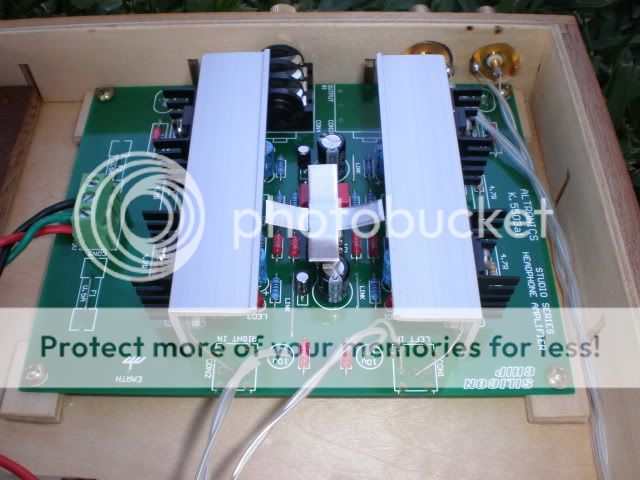  The unfortunate thing is that with renovations happening here at the moment I haven’t had any real chance to test it out fed from a good DAC rather than from a old Luxman CDP. Still sounds pretty darn good though. Will get test with a better feed soon. cheers.. jeffc |
|


 Tell you what big guy....... I still have my trusty old Fujifilm MX-1200 (in MINT condition) and it's sitting here gathering dust these days.... it has EXCELLENT macro capability and a great little tool for PCB close ups (even though it's "only" 1.3 mega pixel) review here:
  )
) If they did will you be implementing the JLH in your build or are you saving it for something else?