|
|
Post by PinkFloyd on Jan 22, 2009 19:43:17 GMT
Woah Bro ! What's with all that heavy metal between the driving source and the amp ?   Counting from whatever you have driving the SCHA I come up with: RCA Jack>RCA Plug>Cable>RCA Plug>RCA Jack>Cable>RCA Plug>RCA Jack ! a DAMN lot of hardware beteen two points that is has a serious potential for signal degradation and possible loss of signal integrity at some point if/when one of those "never should have been selected for high quality audio use" RCA jacks goes south on you the connection not one that is gas tight so even though high on the "looks cool" side of the coin you would be better off losing the pcb mounted connector and hardwiring the input jacks directly to the pcb pads  I was going to say the same thing last night Rick but assumed there must be some obscure reason why there are so many connections in there (thinking he may want to unplug them for some reason  ) Yes, would be a lot better if everything was hardwired ;D |
|
Deleted
Deleted Member
Posts: 0
|
Post by Deleted on Jan 22, 2009 19:50:07 GMT
Rick The SC HA was just a part of the project in the photo. John was simply following info provided by the magazine, and using the photocopy that came with his kit,which included the parts mentioned. I think he did pretty well for a "newbie". Alex  |
|
robertkd
Been here a while!  Electronics Engineer from sunny Queensland
Posts: 111
|
Post by robertkd on Jan 25, 2009 9:21:28 GMT
Ok more work on the protoype  All right 2 no no's the soldered earth connection and a piece of tape over exposed mains connection, piffft it's a prototype  Anyways now self powered, still sounds great really clean and very very quite  shush were going Elmer hunting,...   |
|
Deleted
Deleted Member
Posts: 0
|
Post by Deleted on Jan 25, 2009 9:44:59 GMT
Robert
Looks like we need to find a source of low capactance screened cable that is thinner than most, but thicker than the inners from SVHS cable, which although it can be used at a pinch, is not ideal. Tandy used to sell small rolls of suitable cable years ago, but that disappeared around the time Woolworths acquired D.S.E. and Tandy. Jaycar also used to stock some very nice blue covered stuff, and supplied it with their "Blueprint" kit versions.
Leo is also currently trying to find some more suitable screened cable for amplifier internal wiring, as distinct from the stuff used in interconnects.
Are you going to increase the value of your input capacitors ?
Alex
P.S. Has Michelle Nicolle's disc arrived yet ? If so, do you think it is as good as Chong thinks it is ?
|
|
robertkd
Been here a while!
Electronics Engineer from sunny Queensland
Posts: 111
|
Post by robertkd on Jan 25, 2009 10:17:28 GMT
Alex, finding anything half decent these days is a battle As for the disc, no it's on back order bar humbug  also waiting for the DAC, meantime ordered some of these cgi.ebay.com.au/ws/eBayISAPI.dll?ViewItem&ssPageName=STRK:MEWNX:IT&item=270281882554got an extra one if your interested, PM me The transformer whilst not ideal has some benefits like the 7.5 volt taps which should supply the LV for the DAC as I thinking seriously of getting rid of the silly 1/2 supply regulator as stock and running the OP opamp from +/- 15, stay tunned ideal 18-7.5-0-7.5-18 but as you know small pow power transformer are becoming hard to get,.. Also good to see the T-ambient has dropped Robert PS yes I will increase the ip capacitors at some point, just looking at options |
|
|
|
Post by PinkFloyd on Jan 25, 2009 10:41:13 GMT
Alex, David White (white noise audio) used to supply some fantastic shielded hook up wire (see photo) 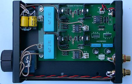 Maybe pop him an e-mail and ask him where he sources it from...... david.white38@ntlworld.com Mike. |
|
robertkd
Been here a while!
Electronics Engineer from sunny Queensland
Posts: 111
|
Post by robertkd on Jan 25, 2009 10:44:26 GMT
|
|
Deleted
Deleted Member
Posts: 0
|
Post by Deleted on Jan 25, 2009 10:48:13 GMT
Robert
Do you have any specs on the transformers ? I wonder if they are wideband enough to work properly with 24/192, which the DAC is supposed to be capable of.
I did think of initially trying a dual reg at +-6v via a JLH, ripping out the rail splitter chip and fitting a couple of 100uF electros in place of the 10Ks, ditch the 1,000uF and the 1N4002 .
0 Volts from the dual supply would go to the CT of the splitter's output. (earth)
If results seemed promising, then extra power supplies would be the way to go. A dedicated 12V for the VREGs, and perhaps +-12V for the opamp . (LM4562 + additional bypass caps.)
Alex
|
|
|
|
Post by cyteen on Jan 25, 2009 18:03:10 GMT
Something to remember with rg178 is that much of it has SCCS as the main conductor (silver on copper on steel). Given a choice go for the rg400 which comes with silver on copper (or should).
|
|
Deleted
Deleted Member
Posts: 0
|
Post by Deleted on Jan 25, 2009 20:54:17 GMT
Robert and cyteen
I already have a small length of mini teflon coax. The problem with most coax cables is that they are simply not flexible enough for normal internal cabling. There used to be far better alternatives available. Even Tandy used to sell small rolls of suitable low capacitance cable. It was a delight to work with. Jaycar also used to supply a blue covered low capacitance cable length with their premium kits.It's just a matter of locating more suitable cable again.
(Easier said than done !)
SandyK
|
|
|
|
Post by cyteen on Jan 25, 2009 22:41:52 GMT
This often comes up as a source: myworld.ebay.com/navships/a selection with ptfe insulation, copper and silver plated copper conductors. (not solid silver only though) with good descriptions to aid choices. I agree that in most cases the bend radius of rg400 type coax is too large for convenient use. |
|
|
|
Post by jeffc on Jan 26, 2009 10:03:32 GMT
|
|
Deleted
Deleted Member
Posts: 0
|
Post by Deleted on Jan 26, 2009 11:24:06 GMT
jeffc and cyteen
Thanks for the links. These should give Leo somewhere to start. I think most of us have trouble readily sourcing shielded cable for internal wiring, to and from Alps volume controls etc.
Alex
|
|
robertkd
Been here a while!
Electronics Engineer from sunny Queensland
Posts: 111
|
Post by robertkd on Jan 26, 2009 12:18:58 GMT
Alex and I thought that was so elegantly put too,.. "go krap in your hands and clap" amazingly it's gone WTF? ;D |
|
Deleted
Deleted Member
Posts: 0
|
Post by Deleted on Jan 26, 2009 12:40:05 GMT
A more Aussie one is "dip your eye in hot cocky shit "
|
|
|
|
Post by PinkFloyd on Jan 26, 2009 22:44:28 GMT
Ok more work on the protoype All right 2 no no's the soldered earth connection and a piece of tape over exposed mains connection, piffft it's a prototype Anyways now self powered, still sounds great really clean and very very quite shush were going Elmer hunting,... That looks a bit of a mess Robert, not what I expected to see after reading your posts, a total pig's ear of a build if I'm being honest. Just WHAT the hell is going on with those Suntan caps (to the left of the photo) ?? Where on earth did you get that loud / 1970's table cloth from? Soldering.... looks like you've taken a molten DUMP on the joints. Horrible looking mate..... Well..... "somebody" had to say it didn't they? |
|
Deleted
Deleted Member
Posts: 0
|
Post by Deleted on Jan 27, 2009 1:03:37 GMT
I think that says it all ? Might not look pretty at this stage, but cobbling together a dual regulated PSU on an old piece of tagboard from the junkbox, shows ingenuity. I doubt that a trained engineer is going to leave the PSU in that form ? ;D |
|
rickcr42
Fully Modded
Rest in peace my good friend.
Posts: 4,514
|
Post by rickcr42 on Jan 27, 2009 1:58:25 GMT
Looks like a "modular" build to me actually.One that you can unplug a single section and plug in the "new" without having to figure out how the hell to wrangle it inside the "box" already crammed full with "this days" best method |
|
robertkd
Been here a while!
Electronics Engineer from sunny Queensland
Posts: 111
|
Post by robertkd on Jan 27, 2009 3:45:53 GMT
Ok more work on the protoype That looks a bit of a mess Robert, not what I expected to see after reading your posts, a total pig's ear of a build if I'm being honest. Just WHAT the hell is going on with those Suntan caps (to the left of the photo) ?? Where on earth did you get that loud / 1970's table cloth from? Soldering.... looks like you've taken a molten DUMP on the joints. Horrible looking mate..... Well..... "somebody" had to say it didn't they? a) their taking a rest b) it's a place mat, unless your referring to the wood looking stuff which is actually wood c) isn't that how it's done? and yeah thanks Mike it needed saying and I promise to do better next time |
|
robertkd
Been here a while!
Electronics Engineer from sunny Queensland
Posts: 111
|
Post by robertkd on Jan 27, 2009 9:36:40 GMT
You know I'm kinda warming to this "molten dump" soldering sooooo  and the good thing about prototyping is for 50c worth of aluminum angle I can try this  just rearrange the deck chairs and voila Alright maybe a $1.oo might rearrange the front panel layout and give it a section on the RH side. |
|
|
|
Post by PinkFloyd on Jan 27, 2009 11:01:09 GMT
hehe..... I'm just trying to liven this thread up a bit and being a rude bastard at the same time..... my apologies Robert, your soldering looks great.... I was a bit "lubricated" when I posted last night and my eyesight wasn't the best..... apologies |
|
robertkd
Been here a while!
Electronics Engineer from sunny Queensland
Posts: 111
|
Post by robertkd on Jan 27, 2009 12:28:33 GMT
no not at all Mike and thank you for pointing out the erors of my ways, I've watched the training video here www.youtube.com/watch?v=lPMHJOgm76Mand ordered the required bits, you know this has been a liberating and learning experience and now I think I now have the hang of it,..  |
|
Deleted
Deleted Member
Posts: 0
|
Post by Deleted on Feb 6, 2009 15:04:18 GMT
I have finally finished my SCHA! It has all of the mods I'm aware of except the super large, yellow caps on the inputs. As originally intended, it has the smallest footprint I could manage, 10.5cm x 14.5cm, for desktop use. Headphone sockets are fitted front and rear, the rear running slave from the front. There is also a line out for my next, matching mini power amp, project. The resistance selector has remained for now but I suspect this will be changed for a line input selector later. There were a couple of last minute case design changes out of necessity, previously intended front panel designs, below, were scrapped, the third photo is the finished article. IDEA 1  IDEA 2  FINAL DESIGN  It did ALL fit inside.... Early stage of assembly  All the gubbins ready for sealing up  Another thankyou to everyone that helped me along way. Chris |
|
|
|
Post by PinkFloyd on Feb 6, 2009 17:42:45 GMT
Absolutely MENTAL! I love it  |
|
Deleted
Deleted Member
Posts: 0
|
Post by Deleted on Feb 6, 2009 20:16:54 GMT
Absolutely MENTAL! I love it So do I ! Chris See if you can find something to cover the exposed fuse for your own protection in the future. Alex |
|


 ) Yes, would be a lot better if everything was hardwired ;D


