Zetex ZTX853/953 Upgrade
Sept 26, 2008 22:46:06 GMT
Post by canjunkie on Sept 26, 2008 22:46:06 GMT
blow by blow guide to fitting the higher rated Zetex ZTX853 & ZTX953.
Farnell's stock numbers in the UK are:
ZTX-853 952-4894 £1.13 each +VAT
ZTX-953 953-4983 £1.17 each +VAT
Farnell still have a £20 ex vat minimum order fee. If anyone is interested but can't make up a minimum order PM me and I'll sort a mini group buy out. Its a simple drop in replacement jop and the position of the transistors makes it an easy solder job.
• Tools required:
a. Suitable screwdriver or hex key for removing of grub screw securing the volume control knob
b. Cross head screwdriver for removal of rear panel retaining screw
c. Hex key for removing main chassis screws
d. Soldering iron, 25 Watt or greater
e. Solder 22AWG (good old fashioned leaded solder is available)
f. Solder wick or solder sucker.
In addition, tools such as the ‘helping hands’ or other PCB support frame are useful and make the job slightly easier. Fortunately, the transistors are reasonably easy to access so the job can be done with the PCB resting on a suitable work surface.
• Components:
g. 1 x Zetex ZTX853 NPN transistor
h. 1 x Zetex ZTX952 PNP transistor
Before commencing disassembly of the amplifier disconnect it from its power supply!
Procedure.
1. Removing the front panel.
a. If necessary, loosen the grub screw holding the volume control onto the potentiometer shaft and remove the volume control. Some knobs, including the original black plastic type are push fit and do not have a retaining screw.
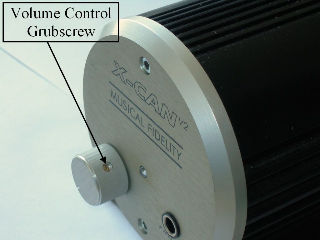
b. Using a suitable size hex key, remove the two fixing bolts that hold the front panel in position. Carefully remove the panel. Take care to ensure the power LED is removed and left attached to the PCB. Some are held in place with a small amount of glue and may require some force to dislodge them. Place the front panel on a hard surface and push it down until the LED dislodges.
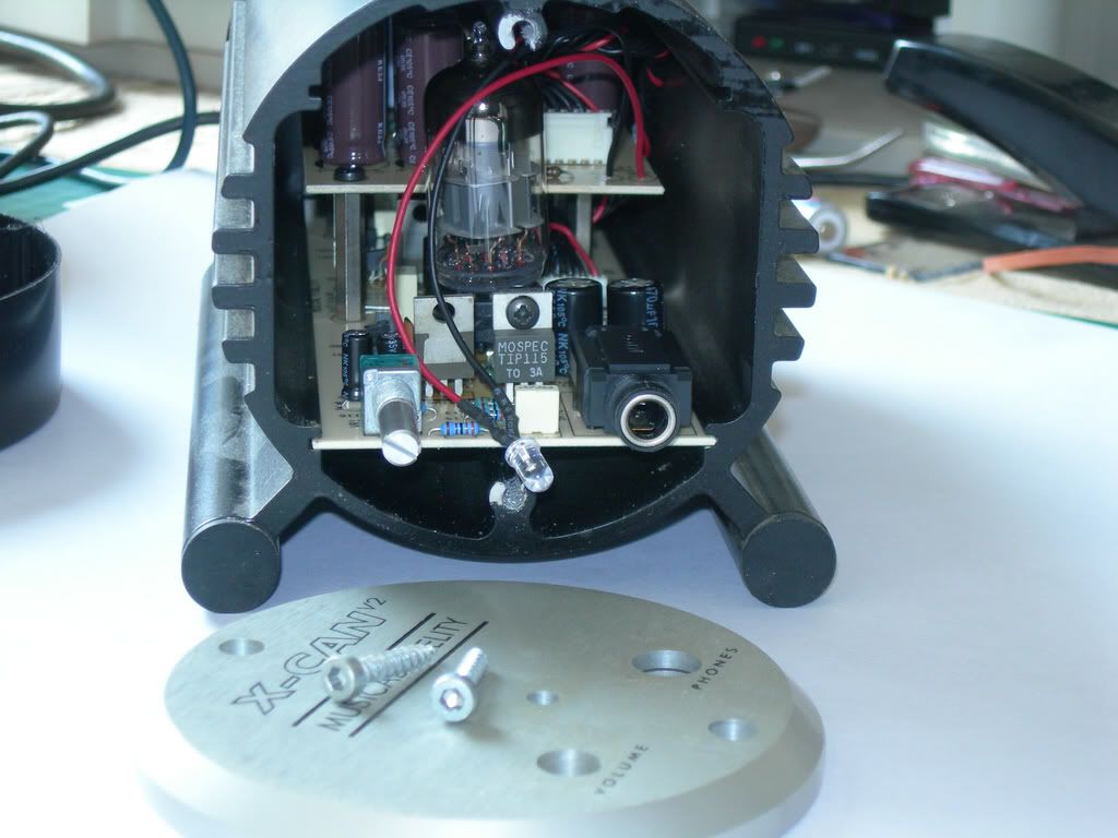
2. Removing the rear panel.
a. Remove the two hex screws securing the rear panel in place. Once you have done this, pull gently and the amplifier PCB’s will slide out of the main housing.
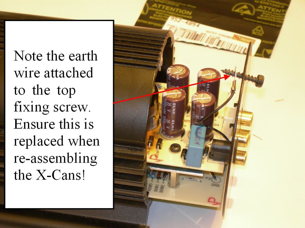
The rear panel can now be removed. It is held in place by a single crosshead screw situated in between the phono sockets.
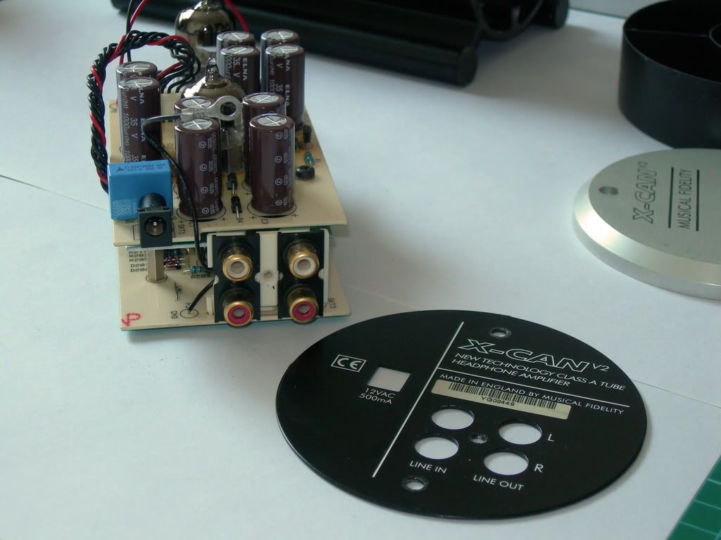
3. Separating the Printed Circuit Boards (PCBS’s)
a. The PCB’s are attached via four crosshead screws and spacers which are indicated on the photograph below. Remove these screws and disconnect the power cable. Put the lower PCB to one side in a safe place. You may prefer to remove the ‘tubes’ before doing this, although if done carefully it is not absolutely necessary.
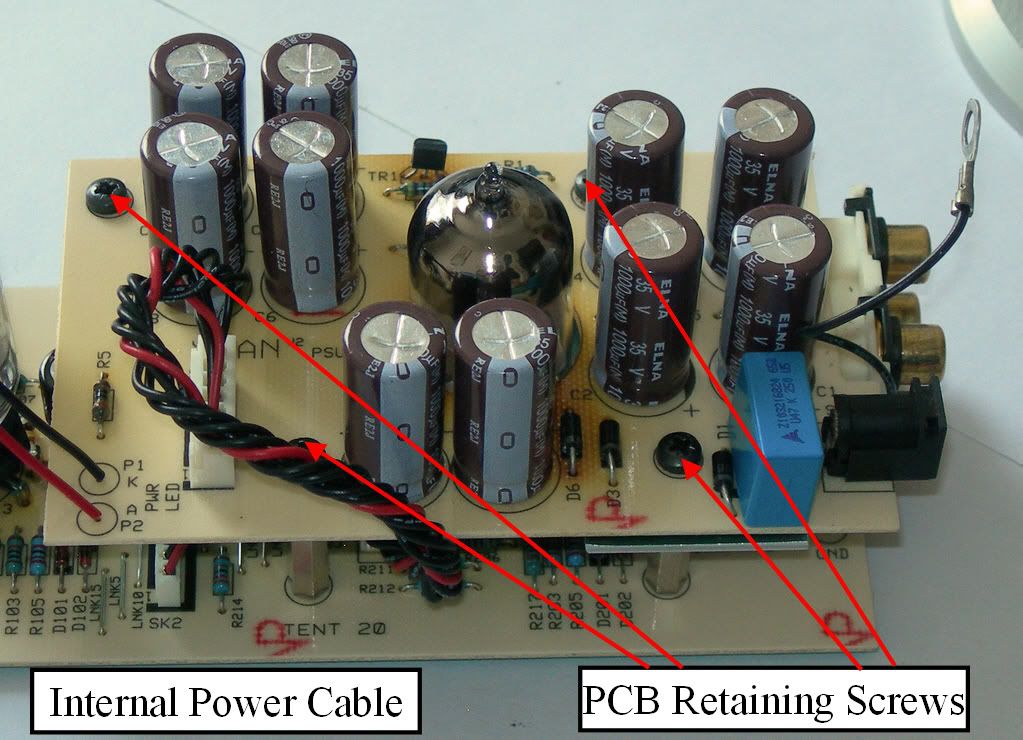
4. Removing the existing ZTX series transistors.
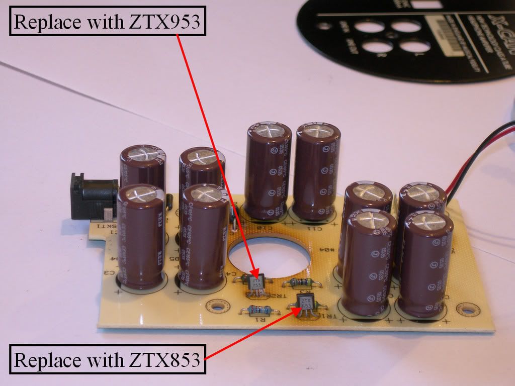
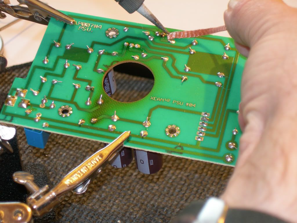
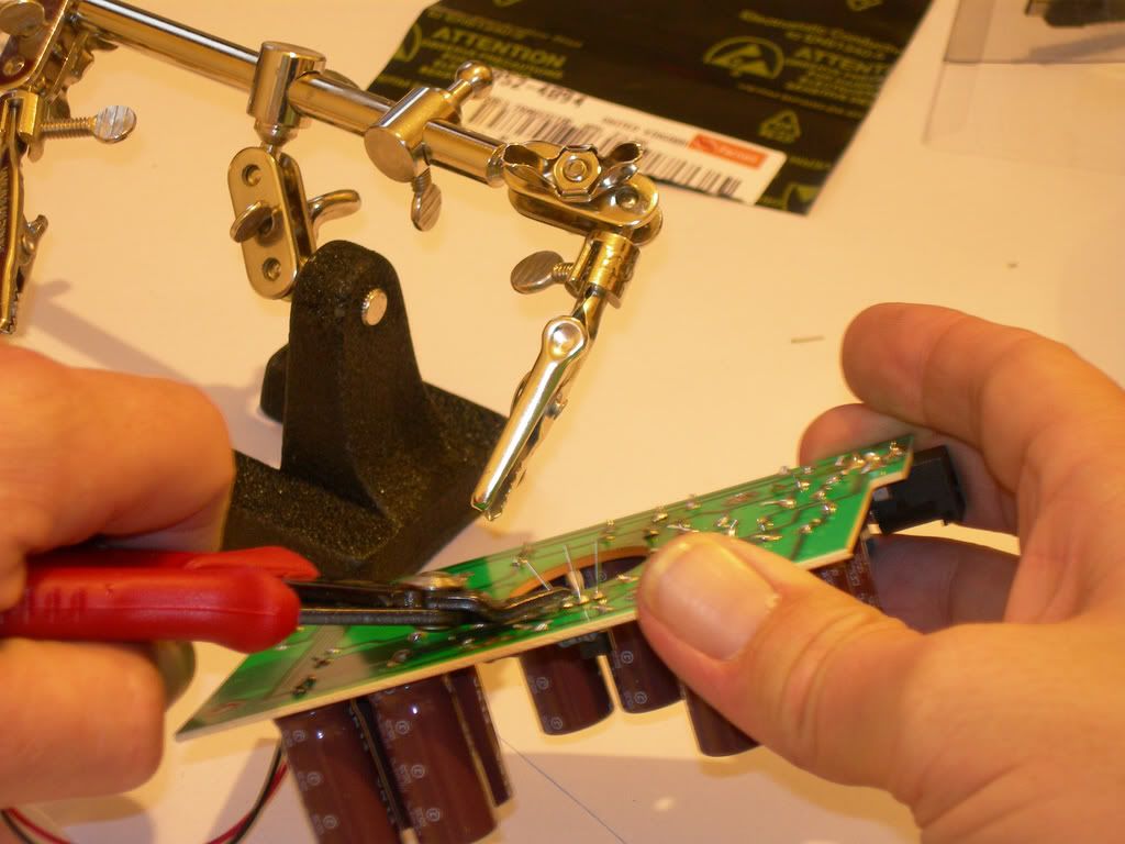
a. Flip the board over secure it so it doesn’t move around when you apply the soldering iron and de-solder tool. De-solder braid is preferable as it will allow removal of most of the original solder, leaving a cleaner joint for soldering the new transistors. The soldering iron should be applied then the de-solder wick. The melted solder will flow up the braid, away from the joint. As you de-solder each leg, give the PCB time to cool down before moving on to the next leg. This will reduce the risk of lifting the PCB copper tracks.
5. Fitting the new transistors.
a. Once you have removed both existing ZTX transistors, insert the innermost replacement transistor, the ZTX953 and solder into place. Remember, clean and tin your soldering iron with a small amount of solder then apply it to the joint so that it heats the PCB pad and the transistor leg. After a couple of seconds apply solder to the joint and it should flow quite easily. It is advisable to wait a few moments to allow the PCB to cool in between soldering each of the three legs. Once all three legs are soldered, inspect the joints to ensure there are no ‘bridges’ between the three legs. If there are you will have to de-solder the joints and re-solder them again, ensuring that you don’t overheat the joint opr apply too much solder. If the solder joints are OK, repeat the procedure for the transistor nearest the edge of the PCB.
b. Note: The transistors should be orientated the same way as the originals – IE, the text should face the same direction as shown in the photo of the original transistors above. The new transistors are printed silver on black so you may want to check the orientation and type in good lighting using some sort of magnifier!
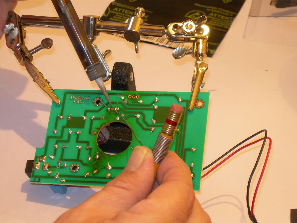
c. After allowing a few seconds for the PCB joints to cool, snip of the transistor legs close to the top of the solder.
6. Re-assembling the amplifier.
a. This is done in the reverse order to dis-assembly. Simply carry out steps 4,3,2 and 1 in that order. Take care to ensure that the earth tag is refitted correctly as shown.
7. Test and Check.
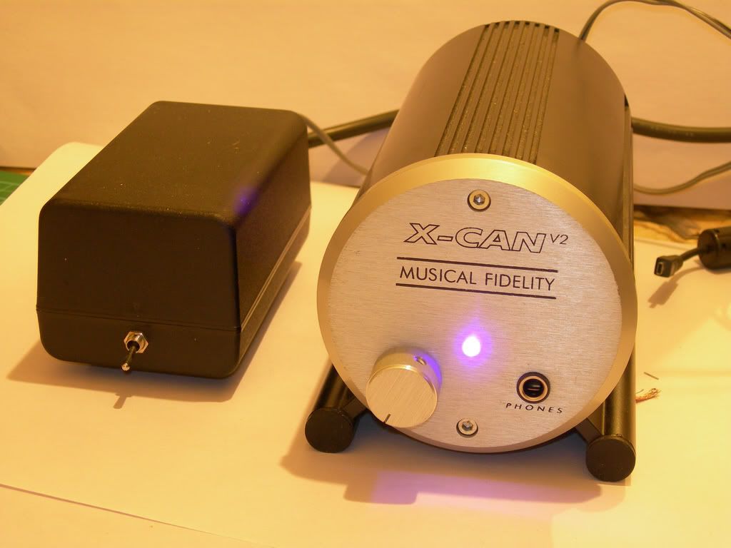
a. Before plugging in a source or headphones, power up the amplifier and ensure the power light comes on. If everything appears satisfactory, power off and attach a source power up again. Attach some headphones and play some music with a low volume setting first.
b. If you here any electronic buzzing, power down immediately.
c. Dis-assemble the amplifier and check the solder joints for ‘bridges and check the orientation of the transistors. If all appears OK you should seek advice from an experienced electronic technician - Or post a help message here
Initial impressions are pretty good, I'll post impressions later.
Farnell's stock numbers in the UK are:
ZTX-853 952-4894 £1.13 each +VAT
ZTX-953 953-4983 £1.17 each +VAT
Farnell still have a £20 ex vat minimum order fee. If anyone is interested but can't make up a minimum order PM me and I'll sort a mini group buy out. Its a simple drop in replacement jop and the position of the transistors makes it an easy solder job.
• Tools required:
a. Suitable screwdriver or hex key for removing of grub screw securing the volume control knob
b. Cross head screwdriver for removal of rear panel retaining screw
c. Hex key for removing main chassis screws
d. Soldering iron, 25 Watt or greater
e. Solder 22AWG (good old fashioned leaded solder is available)
f. Solder wick or solder sucker.
In addition, tools such as the ‘helping hands’ or other PCB support frame are useful and make the job slightly easier. Fortunately, the transistors are reasonably easy to access so the job can be done with the PCB resting on a suitable work surface.
• Components:
g. 1 x Zetex ZTX853 NPN transistor
h. 1 x Zetex ZTX952 PNP transistor
Before commencing disassembly of the amplifier disconnect it from its power supply!
Procedure.
1. Removing the front panel.
a. If necessary, loosen the grub screw holding the volume control onto the potentiometer shaft and remove the volume control. Some knobs, including the original black plastic type are push fit and do not have a retaining screw.

b. Using a suitable size hex key, remove the two fixing bolts that hold the front panel in position. Carefully remove the panel. Take care to ensure the power LED is removed and left attached to the PCB. Some are held in place with a small amount of glue and may require some force to dislodge them. Place the front panel on a hard surface and push it down until the LED dislodges.

2. Removing the rear panel.
a. Remove the two hex screws securing the rear panel in place. Once you have done this, pull gently and the amplifier PCB’s will slide out of the main housing.

The rear panel can now be removed. It is held in place by a single crosshead screw situated in between the phono sockets.

3. Separating the Printed Circuit Boards (PCBS’s)
a. The PCB’s are attached via four crosshead screws and spacers which are indicated on the photograph below. Remove these screws and disconnect the power cable. Put the lower PCB to one side in a safe place. You may prefer to remove the ‘tubes’ before doing this, although if done carefully it is not absolutely necessary.

4. Removing the existing ZTX series transistors.

a. Flip the board over secure it so it doesn’t move around when you apply the soldering iron and de-solder tool. De-solder braid is preferable as it will allow removal of most of the original solder, leaving a cleaner joint for soldering the new transistors. The soldering iron should be applied then the de-solder wick. The melted solder will flow up the braid, away from the joint. As you de-solder each leg, give the PCB time to cool down before moving on to the next leg. This will reduce the risk of lifting the PCB copper tracks.

5. Fitting the new transistors.
a. Once you have removed both existing ZTX transistors, insert the innermost replacement transistor, the ZTX953 and solder into place. Remember, clean and tin your soldering iron with a small amount of solder then apply it to the joint so that it heats the PCB pad and the transistor leg. After a couple of seconds apply solder to the joint and it should flow quite easily. It is advisable to wait a few moments to allow the PCB to cool in between soldering each of the three legs. Once all three legs are soldered, inspect the joints to ensure there are no ‘bridges’ between the three legs. If there are you will have to de-solder the joints and re-solder them again, ensuring that you don’t overheat the joint opr apply too much solder. If the solder joints are OK, repeat the procedure for the transistor nearest the edge of the PCB.
b. Note: The transistors should be orientated the same way as the originals – IE, the text should face the same direction as shown in the photo of the original transistors above. The new transistors are printed silver on black so you may want to check the orientation and type in good lighting using some sort of magnifier!

c. After allowing a few seconds for the PCB joints to cool, snip of the transistor legs close to the top of the solder.

6. Re-assembling the amplifier.
a. This is done in the reverse order to dis-assembly. Simply carry out steps 4,3,2 and 1 in that order. Take care to ensure that the earth tag is refitted correctly as shown.
7. Test and Check.
a. Before plugging in a source or headphones, power up the amplifier and ensure the power light comes on. If everything appears satisfactory, power off and attach a source power up again. Attach some headphones and play some music with a low volume setting first.

b. If you here any electronic buzzing, power down immediately.
c. Dis-assemble the amplifier and check the solder joints for ‘bridges and check the orientation of the transistors. If all appears OK you should seek advice from an experienced electronic technician - Or post a help message here

Initial impressions are pretty good, I'll post impressions later.


