nando
Been here a while!  The Frying Dutchman
Always look on the bright side of life
Posts: 393 
|
Post by nando on Oct 13, 2017 21:47:29 GMT
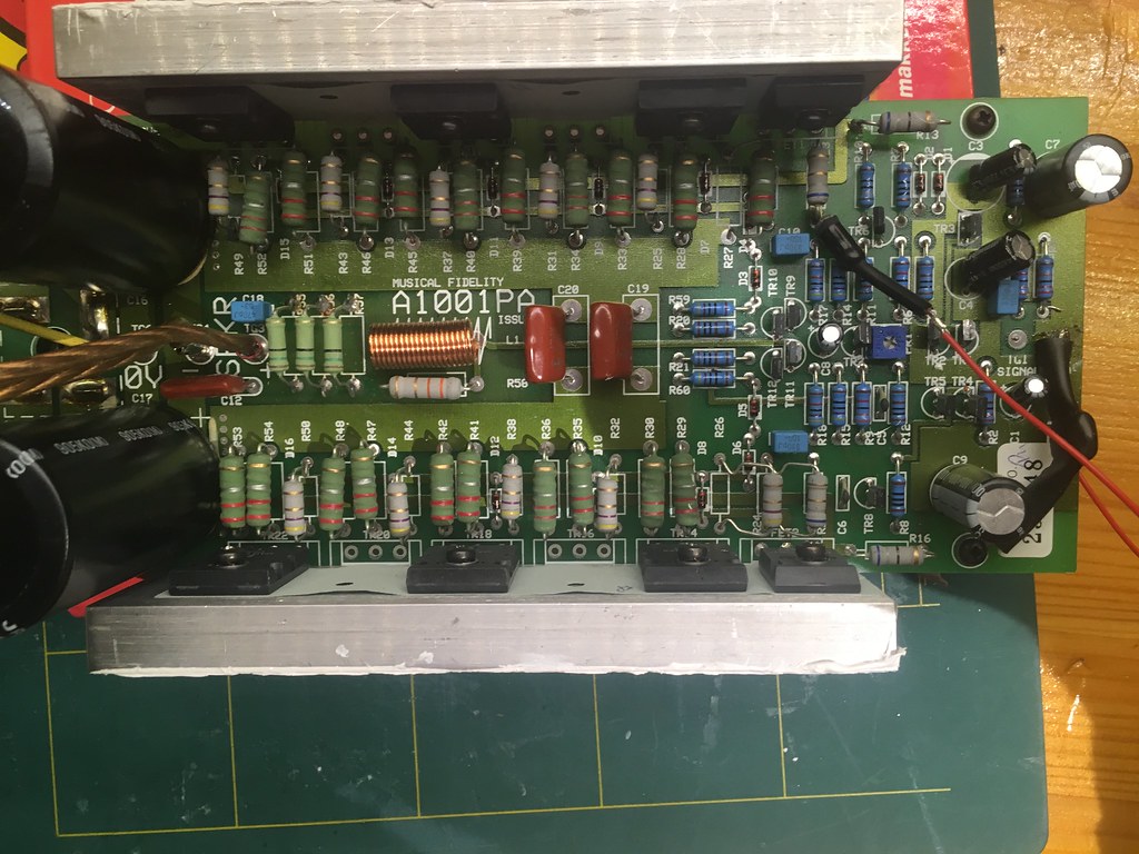
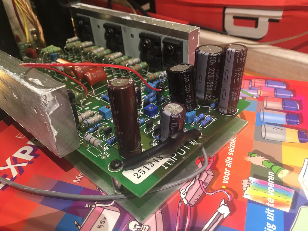
Here's another one... X-A200 mono power amp. 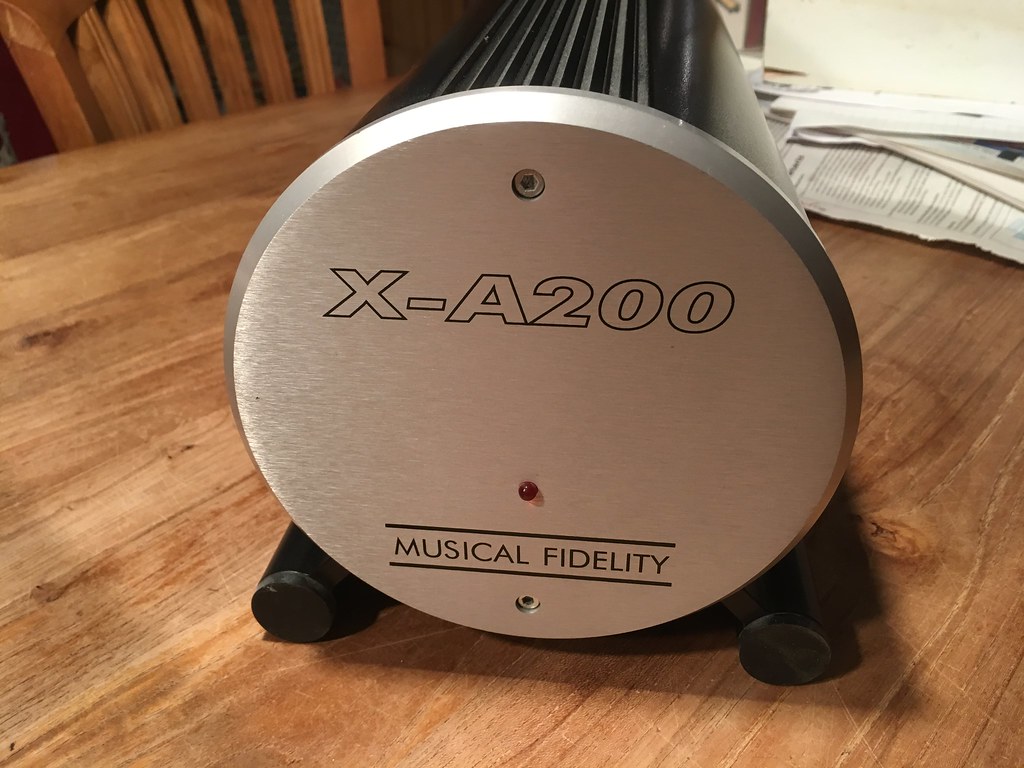 Backside 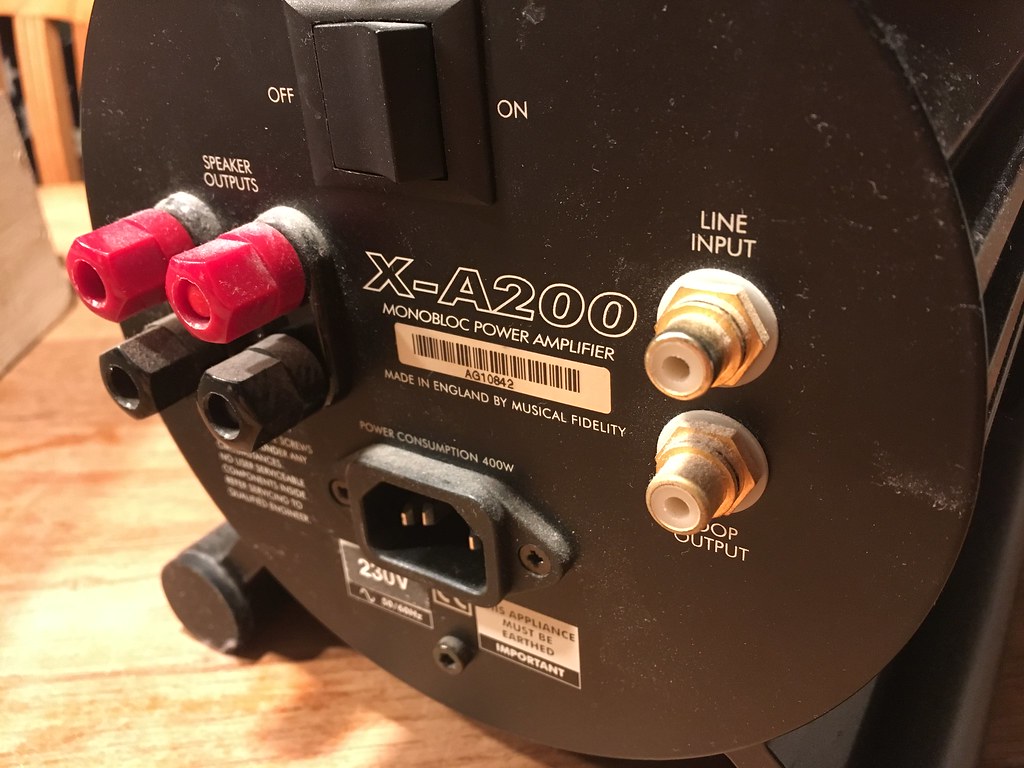 Skrews on both sides to hold the aluminium block on the inside in place. 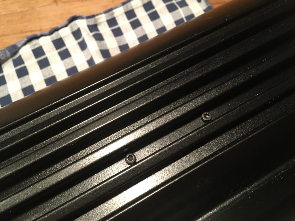 Here is such a alu block with the transistors attached. And cooling paste... 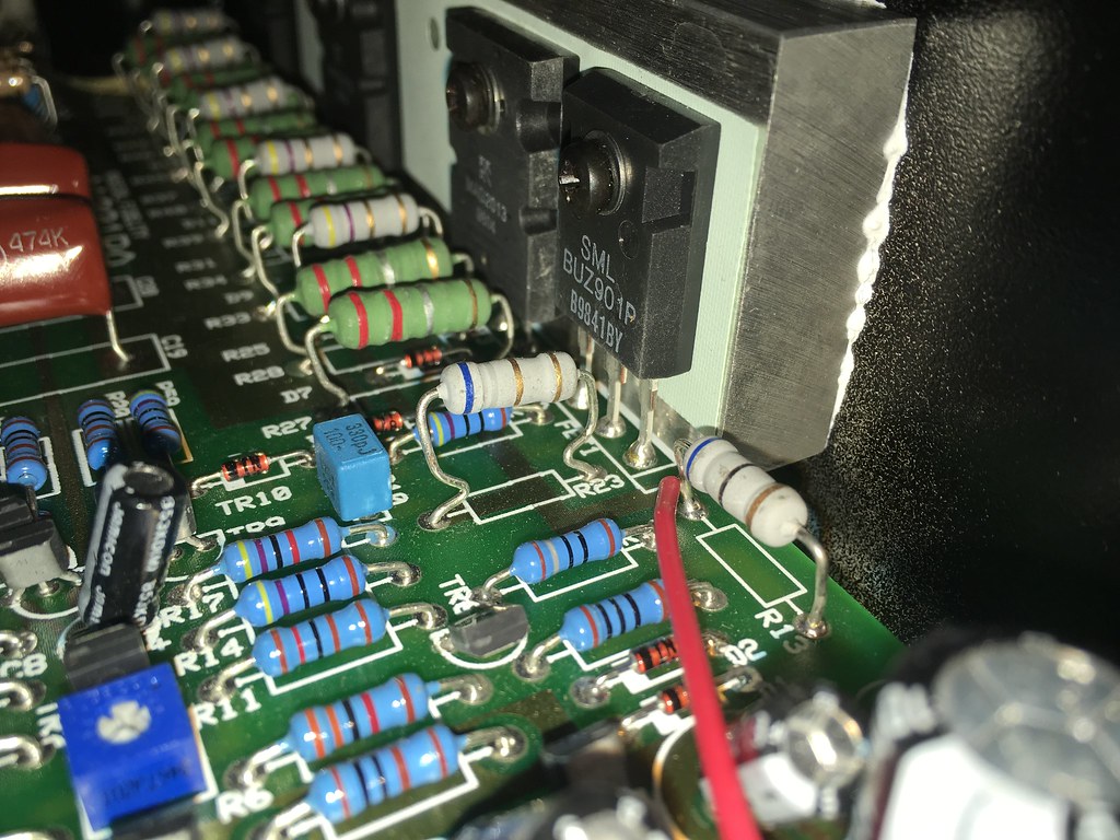 Another member here on rock grotto was trying to mod the x-a200 but couldn't get the pcb out. I now know why and how to do this... The cooling paste is glueing it all together. I wedged a flathead screwdriver between the casing and the alu block. With a little force it poped out of place and the guts of the amp can be pushed out. 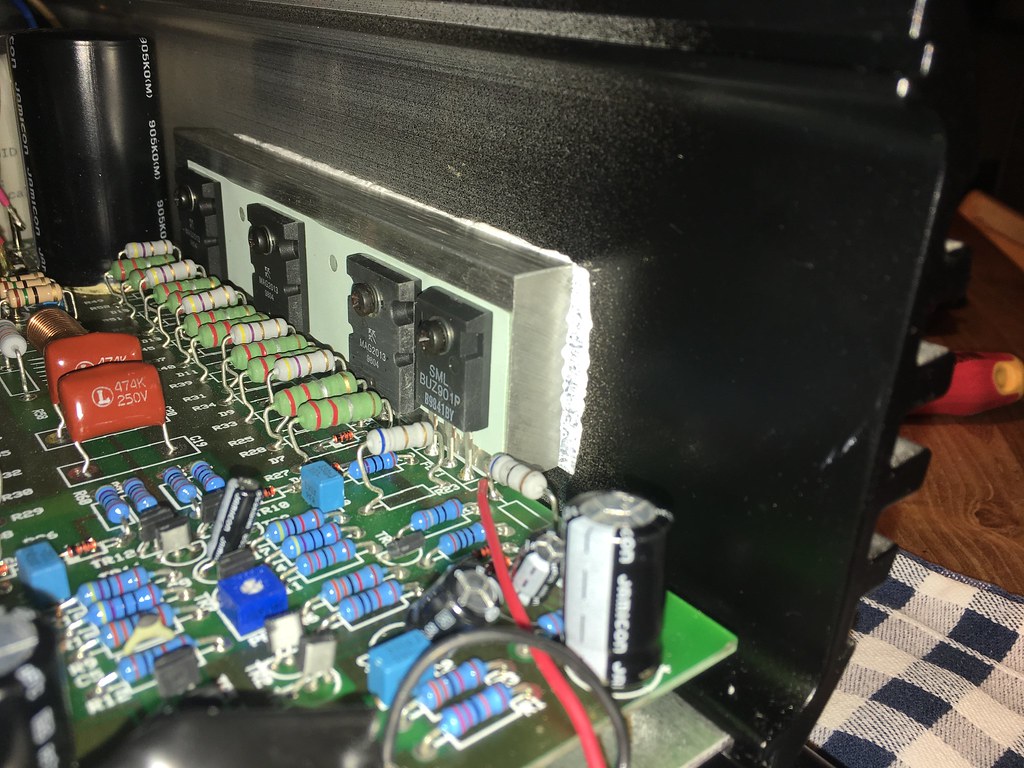 Desoldered the wire for the led on the front panel. 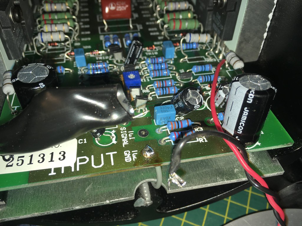 And the pcb is coming out of the back. 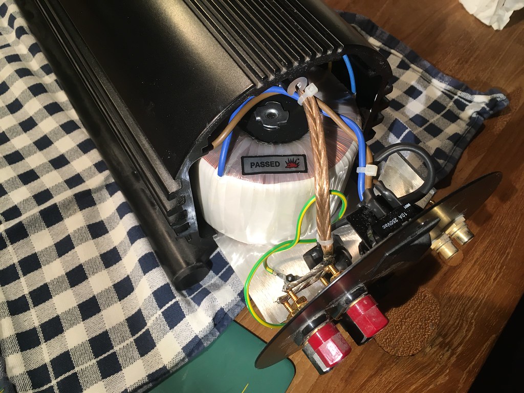 These big ones were one of the reasons to see inside. It's a 6800uF 100V capacitor. I think it will be quite a job to find a good replacement. Then it will be quite a job to actually solder these in place because of the extra alu plate under the pcb which has screws and more cooling paste. 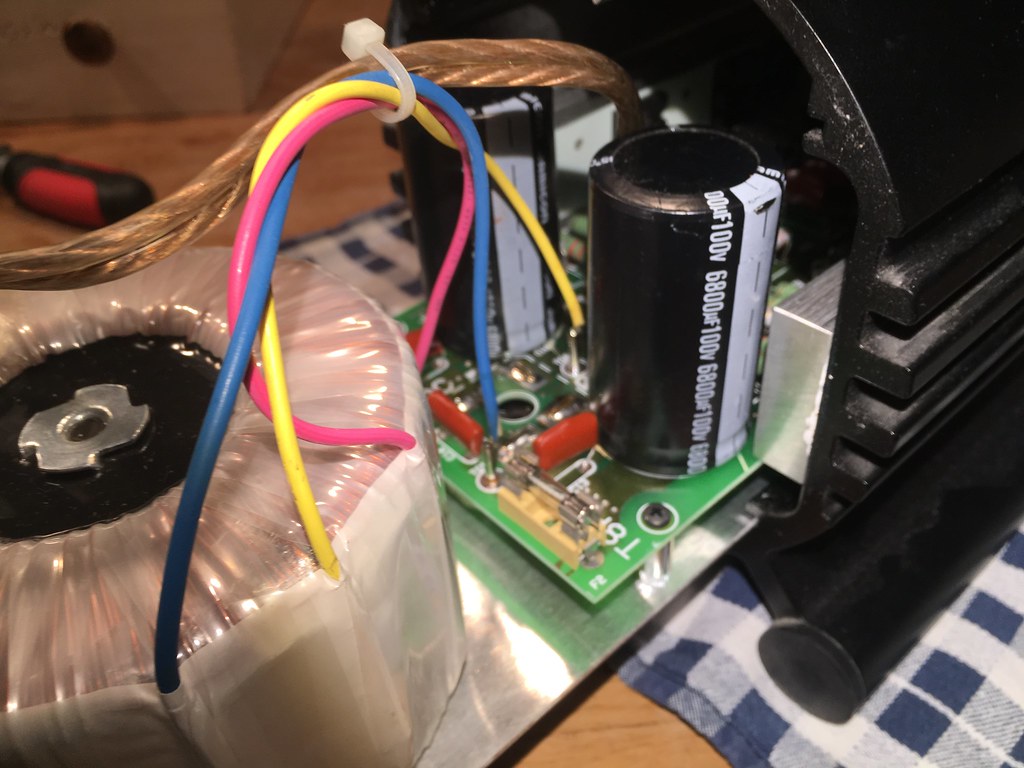 Screws and colling paste under the pcb. 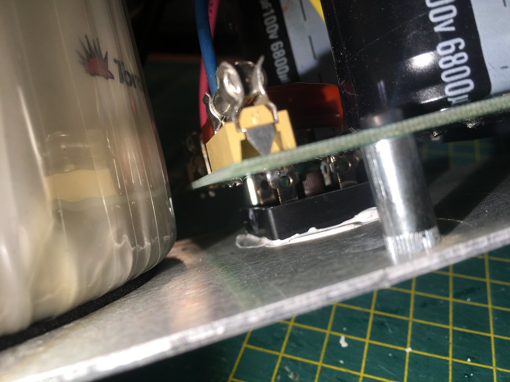 There aren't a lot of capacitors on the pcb. 8 in total. 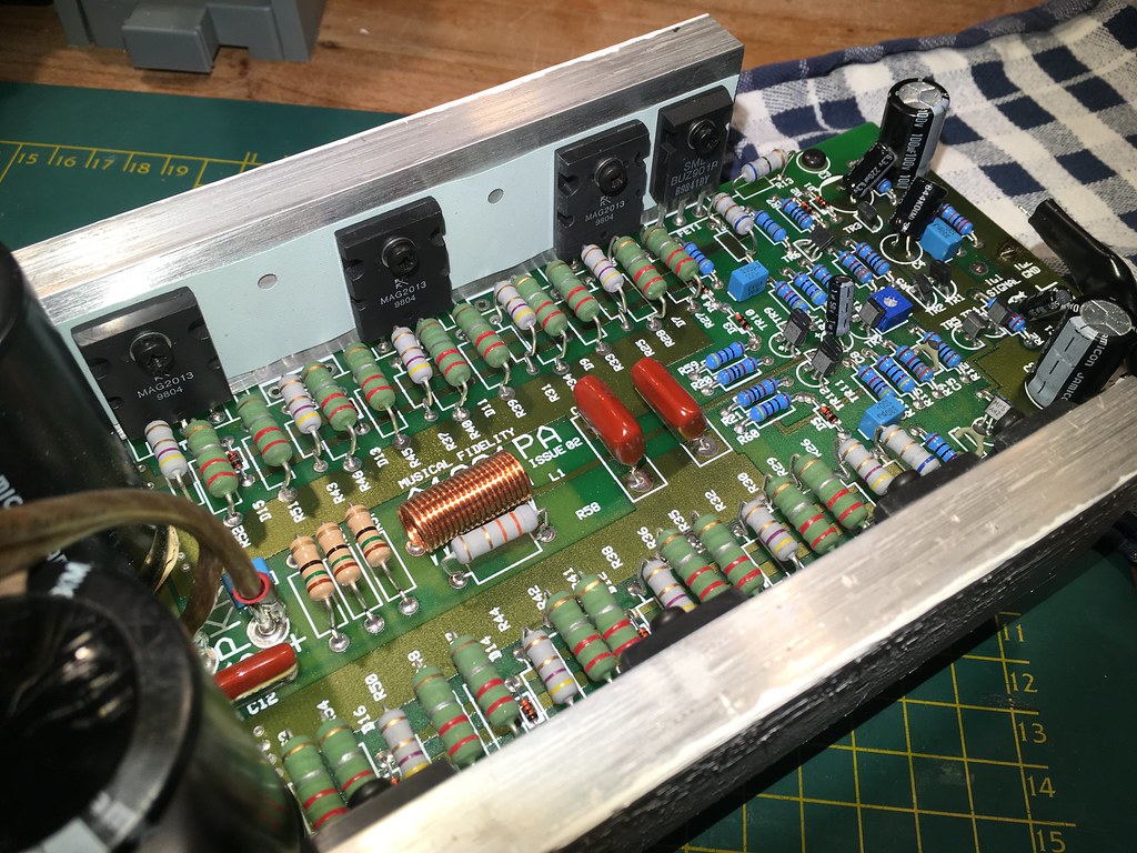 These are the LP series of Jamicon. These aren't the standard stuff but still can be outclassed. 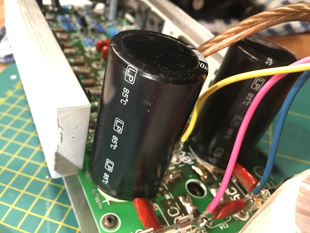 That's all there is.  It says x-a200 on the front and back but A1001 on the pcb. There are holes in the pcb which aren't filled (see the top of the photo below). I read that this amp can be upgraded with a better powersupply and the "missing" components added. 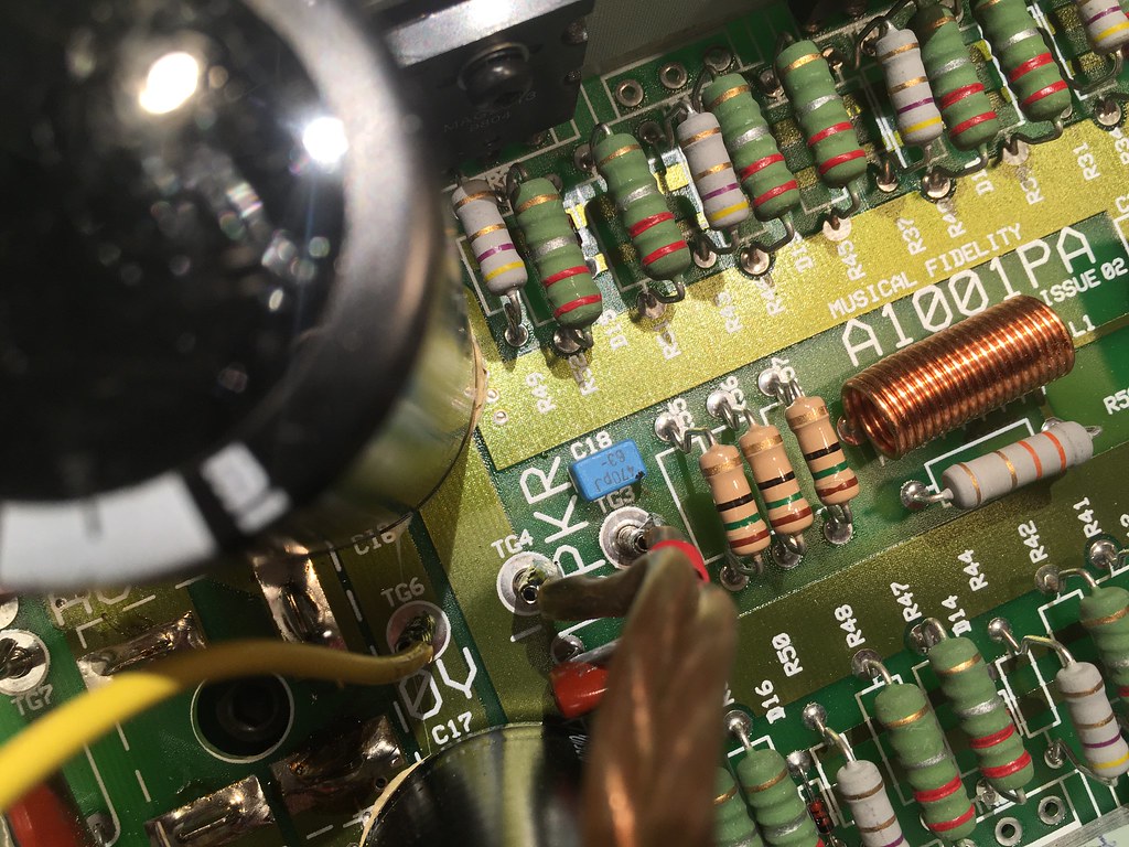 Well any suggestions on what to replace? Besides some panasonification of the electrolycs. 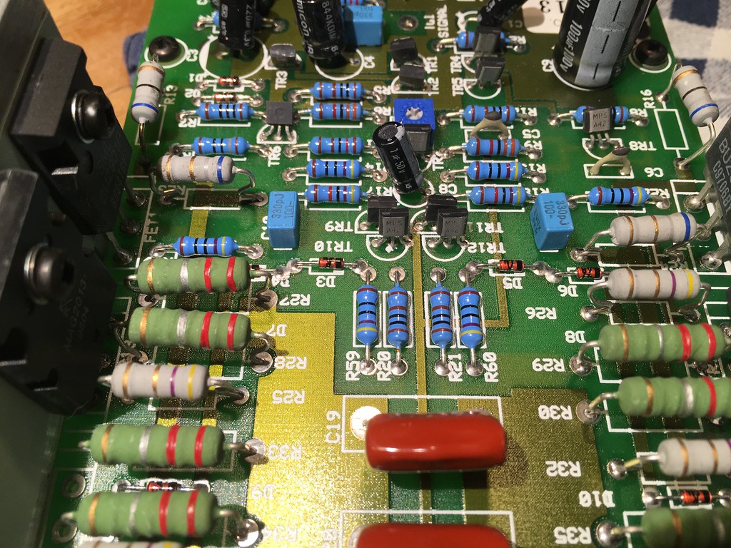 Lots of little stuff. 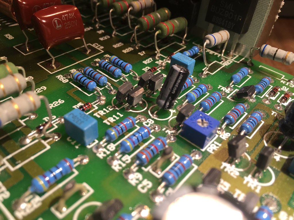 One thing I noticed is that the amp didn't have a very difficult life with me. The amp does not have soot on the pcb from heat. |
|
nando
Been here a while!  The Frying Dutchman
Always look on the bright side of life
Posts: 393 
|
Post by nando on Oct 14, 2017 6:37:10 GMT
First I'm looking for the 6800uF 100V capacitor because this will be the hardesr to find.
I'm finding a lot of capacitor with screw mounts. The original jamicons are snap in mount. Is it possible to place a screw mount (meant for car purposes?)?
|
|
|
|
Post by PinkFloyd on Oct 14, 2017 20:22:28 GMT
First I'm looking for the 6800uF 100V capacitor because this will be the hardesr to find. I'm finding a lot of capacitor with screw mounts. The original jamicons are snap in mount. Is it possible to place a screw mount (meant for car purposes?)? Snap in are the ones to use but make sure the pitch is the same as the Jamicons, the screw in types are not suitable for the board. Ideal candidates are the Cornell Dubilier: uk.rs-online.com/web/p/aluminium-capacitors/7441180/Or the Panasonic: uk.rs-online.com/web/p/aluminium-capacitors/7441180/Both have a lead pitch of 10mm so check the lead pitch on the Jamicon caps to make sure these will fit. That amp is wirewound magnetic / inductive city Nando..... if you want to REALLY (and I mean REALLY) get the best out of it I would replace every last one of those wirewound resistors with MILLS MRA5 (non inductive / non magnetic) types. It will be costly but well worth it........ the Mills will totally bring the best out of the amp! The wirewound resistors are absolutely strangling the amps potential (BIG style) and I wouldn't be racing to replace the capacitors as a priority on this one mate..... I would be running, not walking, to my nearest supplier of Mills MRA5 resistors! I count 30 of them (the wirewounds) in the circuit and @ £4 each you are looking at £120 to replace them with MILLS MRA5 types PLUS VAT / shipping on top so maybe £144 (with VAT). Is it worth the money? OH YES!!!!! www.hificollective.co.uk/components/mills.html |
|
nando
Been here a while!  The Frying Dutchman
Always look on the bright side of life
Posts: 393 
|
Post by nando on Oct 14, 2017 22:02:40 GMT
Oh, jolly another lesson in electronics. Bring it on.
I noticed there are a lot of resistors and not so much capacitors. Different than most other amps I've seen so far.
The resistors are like spools of wire inside? That's making them behave like a electromagnet when current runs through them?
If there is so much EM going on inside it might as well be used as a cannon! There is nothing like a bit of shooting my dubbel barrel railgun in the morning.
You counted some 30 resistors... I count two mono(!) amps so everything is times two. Quite costly indeed.
Which resistors are the problem? The green, yellow (only a few of them) the white or the blue?
You name a specific brand and series resistor, why? Are there more like them (maybe a little cheaper?)
|
|
|
|
Post by PinkFloyd on Oct 15, 2017 9:43:00 GMT
|
|
nando
Been here a while!  The Frying Dutchman
Always look on the bright side of life
Posts: 393 
|
Post by nando on Oct 15, 2017 14:57:02 GMT
Mouser looks a bit cheaper. But then I want to know what benefits it would have to do this mod. The caps will be replaced for sure.
Are you sure these are wirewound and not another type?
Figure out the values of the resistors.
Why not Ohmite, Mike? You raved about these for the x-10d mod.
|
|
|
|
Post by PinkFloyd on Oct 15, 2017 20:10:11 GMT
Mouser looks a bit cheaper. But then I want to know what benefits it would have to do this mod. The caps will be replaced for sure. Are you sure these are wirewound and not another type? Figure out the values of the resistors. Why not Ohmite, Mike? You raved about these for the x-10d mod. Hi Nando, Yes, the ohmite will be good too and also a fair bit cheaper than the MRA5. Rapid keep them in stock and they are certainly a lot better than the stock wirewound resistors..... non magnetic. 50ppm temp. coefficient as opposed to 400ppm for the stock wirewound (lower TC is better). MRA5 are not only non magnetic, they are also non inductive with a low temp coefficient. The benefits are clear, now that you're armed with stuff to research...... research the benefits of resistors that are low temp coefficient, non magnetic and non inductive Versus bog standard wirewound ones  MRA series: www.vishay.com/docs/31801/mra.pdfBog standard wirewound: www.rapidonline.com/pdf/528646_v1.pdf |
|
nando
Been here a while!  The Frying Dutchman
Always look on the bright side of life
Posts: 393 
|
Post by nando on Oct 16, 2017 7:40:07 GMT
Yes, teacher I will do my homework.
Done!
Correct me if I'm wrong.
Wirewound resistors are not suitable in AC circuits because the resitor value changes with the frequency. My first thought was that will not be a problem behind the transformer+diodes+power caps because there will be DC created. But... This only accounts for the base line but then come the music. If the resistor is in the signal path there will be frequencies alternating between 1 Hz and 20.000+ Hz. Therefor the wirewound resistor will change it's value all the time during music playing. Next question is how bad is that? If the value variates within 1% that's negligable.
I wonder how much energy is thrown out of an active resistor and picked up by other components and be affected by it.
|
|
nando
Been here a while!  The Frying Dutchman
Always look on the bright side of life
Posts: 393 
|
Post by nando on Oct 19, 2017 21:10:10 GMT
I'm still not sure whether these resistors in my amp are wirewound, how can I identify them? And how to see these aren't bifilar wound? How to know that power these must be able to handle? 2W, 5W? I've been reading. The wirewound resistors have paracitic capacitence, which is a bad thing. I want a resistor not a capacitor. But if I'm not mistaken this problem becomes a problem at high frequencies and above 50kHz wirewound is unusable in a (normal) circuit. But is this the case in a amp like the x-a200? I guess not but I'm not totally sure. Any ideas? As for the capacitors I only have trouble finding a good replacement for the big ones. I found these: nl.mouser.com/ProductDetail/Cornell-Dubilier-CDE/380LX103M100A082/?qs=sGAEpiMZZMtZ1n0r9vR22dX5NZxAiz78BAe8%2fCsI5aQ%3dThese have a LC logo on the site and text that it's a special factory order. No idea what that means. Ripple current is a bit difficult to find with these but after studying the datasheet I found out that it's (probably) 8700mA and an ESR of 0,033Ohm. That's a dubble RC of the Jamicon when it was new. Oh by the way... cooling paste is nasty, poisonous, sticky, *@$&# stuff. |
|
nando
Been here a while!  The Frying Dutchman
Always look on the bright side of life
Posts: 393 
|
Post by nando on Oct 21, 2017 15:44:46 GMT
For the resistors I have been puzzeling the colors and types. Types (carbon, wirewound etc.) are still a mystery to me. Please correct me if I'm wrong... What max power should these resistors be able to handle? 2W, 5W, 10W? Of course larger is better at handling heat and is a saver bet but I want to know for sure. This is a wirewound 0.22 Ohm 5% resistor. 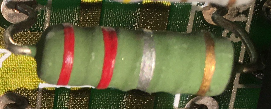 6.8 Ohm 5% carbon resistor (?) 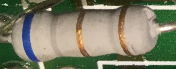 4.7 Ohm 5% carbon resistor (?)  15 Ohm 5% carbon resistor (?) 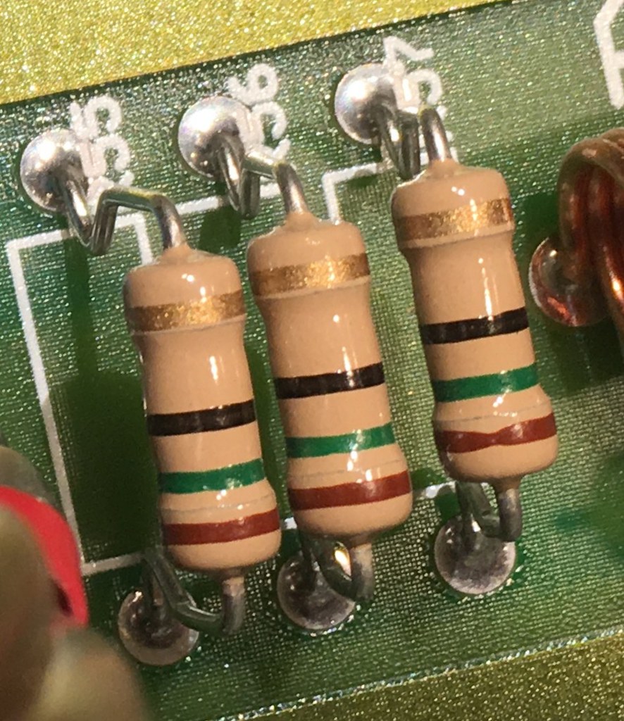 3.3 Ohm 5% carbon resistor (?) 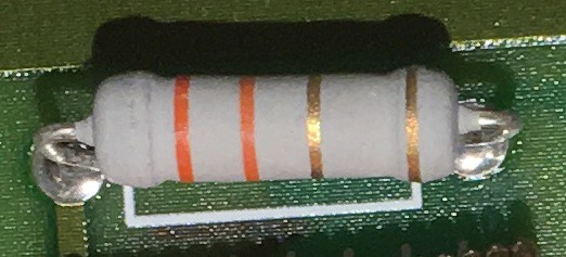 |
|
|
|
Post by PinkFloyd on Oct 21, 2017 20:48:09 GMT
I would say they were all 3 watt.
|
|
|
|
Post by PinkFloyd on Oct 21, 2017 20:49:39 GMT
I would say they were all 3 watt. Go with 5 watt replacements. |
|
nando
Been here a while!  The Frying Dutchman
Always look on the bright side of life
Posts: 393 
|
Post by nando on Oct 22, 2017 21:58:16 GMT
I would say they were all 3 watt. Go with 5 watt replacements. So only the green ones are wireeound and would be a good choice to replace with a 5watt mills mra5? |
|
leo
Been here a while!  Team wtf is it?
Posts: 3,638
|
Post by leo on Oct 31, 2017 8:08:49 GMT
The green ones look to be wire wound , the grey ones are either thick film or wire wound and those brown/beige ones are 1-2 watt carbon . I'd say the 2r2 wire wound ones could be the output device emitter resistors . Its hard to tell from the photo but it seems some of the suspect emitter resistors go to pads where theres no output transistors .The 3r3 grey one could be part of the zobel network. The 6r8 hard to say maybe feeding the output devices
I don't know this amplifier so can't really suggest what to try, tbh you have to be careful with high powered amps, some types of parts can be used on purpose to keep it stable , if something like this would to go unstable it could cause disaster to your speakers if theres no output DC protection.
Before fiddling with it I'd take measurements first and write them down, bias current etc and then compare after the mods are complete to be on the safe side.
|
|
nando
Been here a while!  The Frying Dutchman
Always look on the bright side of life
Posts: 393 
|
Post by nando on Nov 3, 2017 12:46:39 GMT
Thanks, Leo! Good advice.
So these wirewound could be making the circuit stable? Is that because wirewound resistors have inductance and resist change in current. If that inductance is gone the current could be fluctuating (out of controle)?
I won't be changing the resistors quite yet. Not before I am sure it is safe. Measuring is something I can't really do without a oscilloscope.
|
|
nando
Been here a while!  The Frying Dutchman
Always look on the bright side of life
Posts: 393 
|
Post by nando on Jan 21, 2018 11:32:09 GMT
Update:
I do have an oscilliscope now but haven't done measuments on the xa200 beast. I'm not sure yet how to measure this kind of power safely. Don't want to blow up my nice Metrix ox8042 scope.
I have done one x-a200 power amp now. It works perfectly. It is quite a messy job to get the guts out and in the casing. The cooling paste is really annoying. But it worked out fine. The second one is a (near) future project.
I replaced the electrolytic caps only. All were replaced with the same value caps but higher max voltage and from top brands. Casing size wasn't a problem
The big 2x Jamicon 6800uF were replaced with CDE 10000uF with double the ripple current of the Jamicons.
I sought the best caps in terms of ripple current, not looking at price much. There are only 8 caps in the amp so it wasn't going to be a very expensive project anyway. So I ended buying caps that have 5 to more than 10 times the ripple current of the Jamicon version and low esr as well.
Brands are 2x UCC (United Chemi Con), 4x Nichicon and 2x CDE (Cornell Dubilier).
|
|
nando
Been here a while!  The Frying Dutchman
Always look on the bright side of life
Posts: 393 
|
Post by nando on Feb 17, 2019 17:09:03 GMT
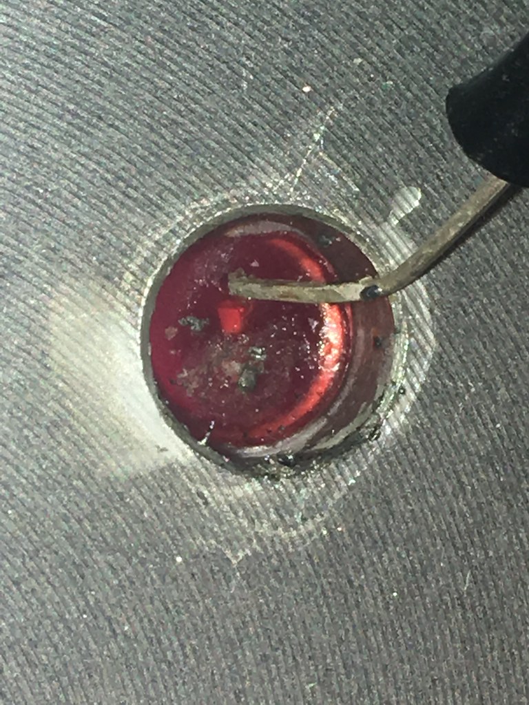
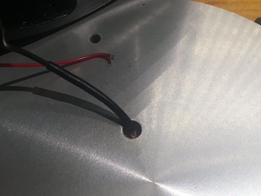
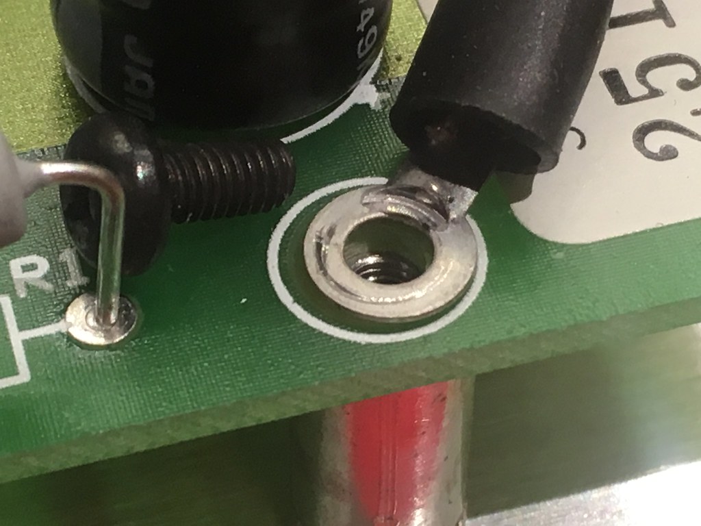
My last post stated the second x-a200 was to be recaped in the near future. Turns out to be more than a year. Today I recaped the second one. But there is a problem with this one. The wire of the led broke of when I removed the front plate. It broke off right on the led so there is no lead to solder it on again. I guess I'm goning to have to replace the led. Any idea what kind of led this is? I want the red one with the same value.
The little black spot is where I tried to solder something but it was beyond repair.
|
|
nando
Been here a while!  The Frying Dutchman
Always look on the bright side of life
Posts: 393 
|
Post by nando on Feb 17, 2019 17:45:27 GMT
Here are some more photo's of the second recap.
This is what I found when I opened the front plate.
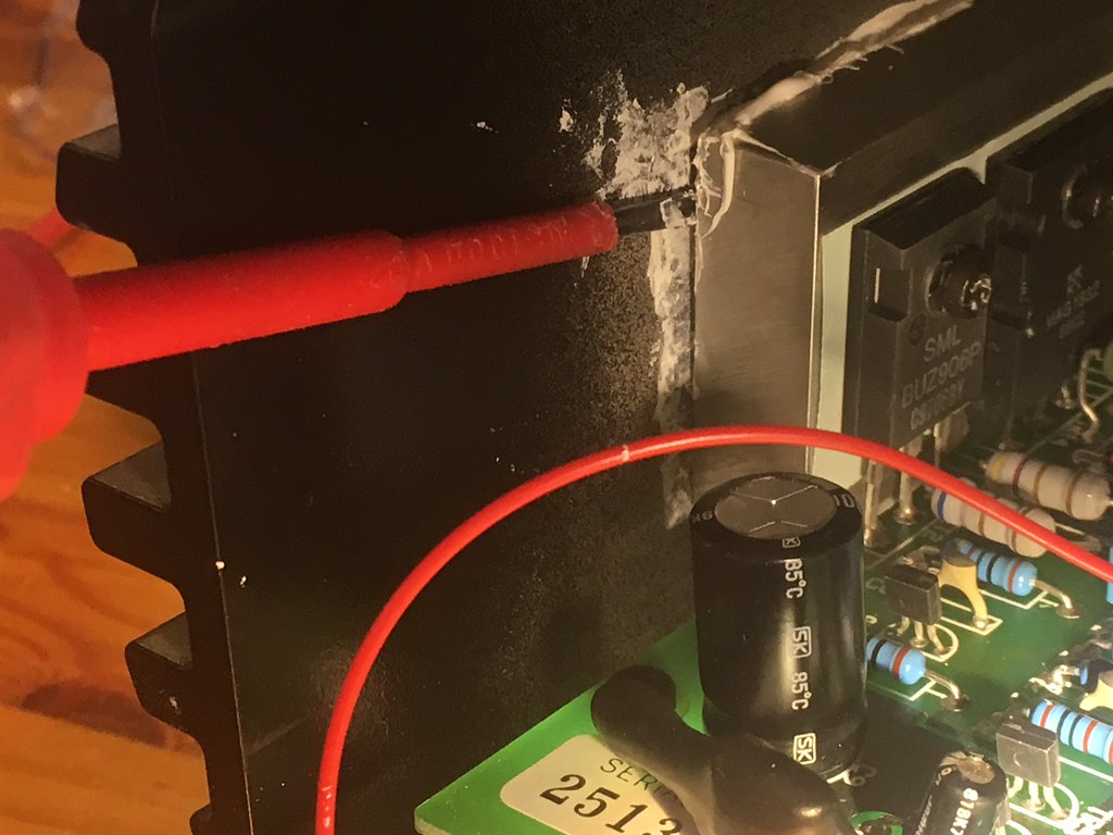
The aluminium block is almost glued to the black outer casing. This is one way to get the two loose.
Don't forget this one!
|
|
nando
Been here a while!  The Frying Dutchman
Always look on the bright side of life
Posts: 393 
|
Post by nando on Feb 18, 2019 9:38:50 GMT
And the amp works. No smoke, just good music! (depending on your taste of course)
What I really hate about this amp is the vast amount of cooling paste. This rotten goo gets everywhere! You can't not get it on your hands and then it gets, in the table, tools, clothes, everywhere!
I tried to scrape the paste off when I opened the amp to put it back when closing the casing but nonetheless it finds it way around. Yuk!
|
|
nando
Been here a while!  The Frying Dutchman
Always look on the bright side of life
Posts: 393 
|
Post by nando on Mar 3, 2019 21:11:12 GMT
Any idea about the led in the amp?
|
|
|
|
Post by PinkFloyd on Mar 4, 2019 11:28:20 GMT
Any idea about the led in the amp? It'll be the standard red one MF used in the X-Series Nando, I have a few kicking about so e-mail your address and I will send you one. Mike. |
|
nando
Been here a while!  The Frying Dutchman
Always look on the bright side of life
Posts: 393 
|
Post by nando on Mar 6, 2019 19:46:05 GMT
Mike, you were right (as usual). I have to get my head arond the whole “whack the plate on card board” thing. I’ll wait when the led arrives.
|
|
|
|
Post by PinkFloyd on Mar 6, 2019 20:07:17 GMT
Mike, you were right (as usual). I have to get my head arond the whole “whack the plate on card board” thing. I’ll wait when the led arrives. I posted you the LED yesterday so it will be with you soon. Get yourself a wooden chopping board and a sheet of A4 paper. Lay the sheet of A4 paper on the wooden block. Forget my "slamming down" method (I have done tens of these without so much as a blemish) I don't think you're too comfortable with that  Place your face plate (LED side down) onto the A4 sheet of paper (with wooden block underneath) and bear down on the faceplate, that will be enough to pop the LED free from the face plate...... simple as that! Dont attempt to drill the LED out / hammer it out..... follow the above and it will pop out nicely. Mike. |
|
nando
Been here a while!  The Frying Dutchman
Always look on the bright side of life
Posts: 393 
|
Post by nando on May 29, 2019 19:03:49 GMT
I replaced the led. I put the front plate on my table and hit the led with a heavy hamer. I thiught that was a hood way because I could hit it quite precisely. It worked perfectly.
The new led didn’t slide in all the way in the front plate though.
|
|
|
|
Post by eightdigitword on Mar 11, 2020 20:40:56 GMT
hey, also got hold of a pair of XA200! soon i can open an X series museum.
i'm sure i seen on a forum way back that someone populated the missing transistors? was this you? or do you know anything of this?
what would this even do? more power? questions then are if the supplied PSU and output components would be up to it? im more curious than anything and will most likely never bother. 200w available to each LF channel will be more than enough. my existing XA-100's with 100w seem limitless.
Im gussing the A1001PA and had these populated? although i see from the manual it too was 200W.
mine were spares/repairs find so i have other jobs before this is looked at, thought id fling it out there early.
Also FYI/info for folk searching in the future that may need a replacement. The transistors in mine were either different from the SAP fitted at another time or have been replaced. either way they work. chips used are Toshiba A1943 (PNP) and C5200 (MPN)
Cheers.
|
|


