|
|
Post by smokeycigar on Nov 1, 2013 6:33:44 GMT
HI all, I have had a perreaux SXH2 headphone amp collecting dust in the cupboard for many years. I have had two of these in the past, and both died the same way. Basically, I would listen to my HD650 through it and would fall asleep. When waking up in the morning, the unit's led us out and the amp didn't function any more. First step was to replace the fuse, but it keeps blowing. So in to storage it went, until many years later. So I opened her up, and de-soldered each positive log of the diodes for some testing. Powered again and fuse still blows. Tested all diodes with a MM, and they both read well. Now I'm not expert, but I would assume the toroidal is the culprit? it's a 12-0-12 with a sheild between the primary/ secondary windings. Any ideas on what the issues to help a fellow member out? See below pic of PCB 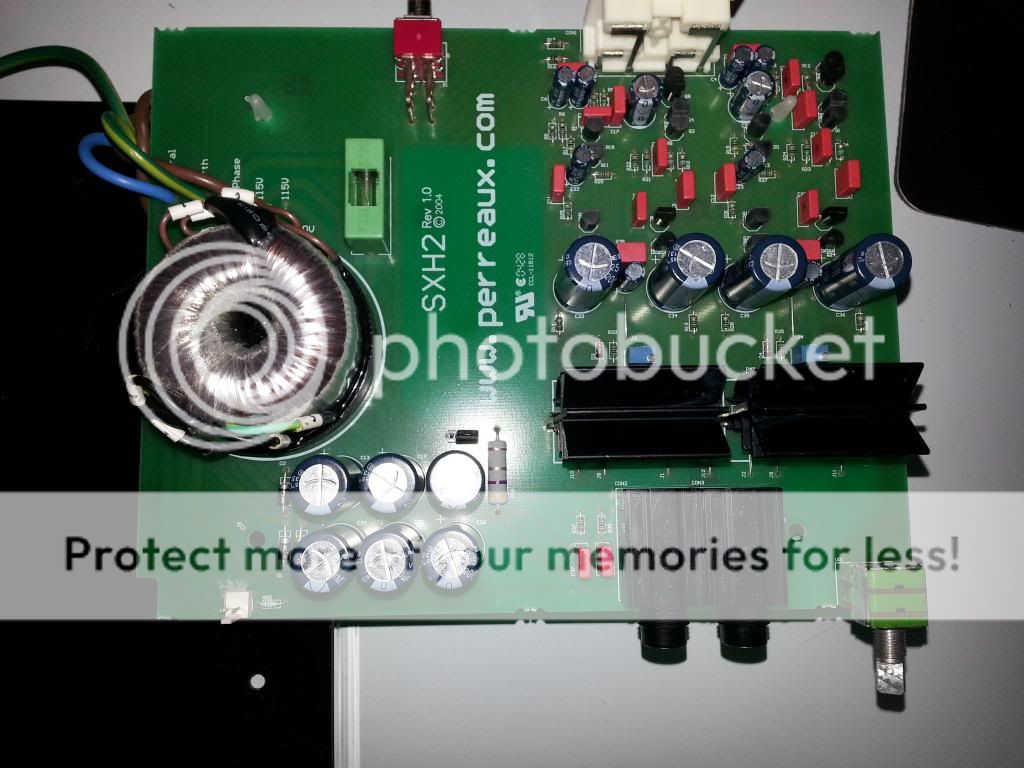 Below Pic is the tracks on the PS area, including the secondaries of the transformer  |
|
Deleted
Deleted Member
Posts: 0
|
Post by Deleted on Nov 1, 2013 6:55:13 GMT
smokeycigar
What is the diode under the PCB for ?
If it is on the filter capacitor side of the 4 rectifier diodes, then your transformer would appear to be damaged.
Check for a reading on the resistance scale between the primary and secondary windings with the diodes still out of circuit, as well as both windings to the mounting bolt.
A high voltage surge can damage a transformer . Is there any obvious discolouration of the transformer ? Does the transformer label show the secondary voltages and the VA of the transformer ?
Alex
|
|
|
|
Post by smokeycigar on Nov 1, 2013 7:10:16 GMT
Hi Alex,
The diode under the PCB is for the power LED.
Sorry, what is on the filter capacitor side of the 4 rectifier diodes? (didn't understand your question)
Transformer doesn't have any visible discoloration.
It doesn't have a mounting bolt.
Transformer spec is 12-0-12/ 10VA with static shield
No continuity between primary and secondary
No continuity between primary and static shield.
Seems there is continuity between the the static shield and both secondaries. Assuming this would be the issue. Do you concur?
The other question is where to get a similar transformer with a static sheild. I can't seem to find them.
|
|
Deleted
Deleted Member
Posts: 0
|
Post by Deleted on Nov 1, 2013 7:21:48 GMT
Yes, I agree. You will need to take size measurements of the transformer. You may even find one that is a similar size but a little higher VA rating.
You may have difficulty sourcing one of those with a screen. I would try fitting one without a screen.
Alex
|
|
|
|
Post by smokeycigar on Nov 1, 2013 7:27:18 GMT
Yeah, might have to go the no screen route. Always wanted a screen for all my projects, but never found a tranny like that off the shelf.
The size of this tranny is hard to source. 47mm wide/ 30mm high. All 15 VA's are around 60mm.
Grrr...
|
|
Deleted
Deleted Member
Posts: 0
|
Post by Deleted on Nov 1, 2013 7:55:45 GMT
Yeah, might have to go the no screen route. Always wanted a screen for all my projects, but never found a tranny like that off the shelf. The size of this tranny is hard to source. 47mm wide/ 30mm high. All 15 VA's are around 60mm. Grrr... Smokeycigar There appears to be plenty of room to mount a shield between sections if needed . You could fabricate one from tin plate . Regards Alex |
|
|
|
Post by smokeycigar on Nov 1, 2013 8:31:11 GMT
I will need to install a tranny with a width of around 60mm (can't find anything smaller in 15VA)
My plan:
- Get a fully encapsulated one so it can't short on anything
- I will need to loose the surface mount fuse and get an inline holder.
- I will need to abandon the PCB connectivity from the IEC socket to surface mount tranny, and just directly wire the replacement to the switch and IEC socket.
- Glue the replacement tranny to the PCB.
That should work.. I think.
The unit also uses Elna and wima caps. So not sure it's worth modifying them. Tracks are pretty thin too.
|
|
|
|
Post by smokeycigar on Nov 1, 2013 12:13:46 GMT
One more thing. I have been looking at replacing that resistor next to the PS smoothing caps.
Does anyone know the wattage and value? Looks like a 3 watt 4.7 Ohm 5%
|
|
Deleted
Deleted Member
Posts: 0
|
Post by Deleted on Nov 1, 2013 12:49:41 GMT
Smokeycigar There appears to be plenty of room to mount a shield between sections if needed . You could fabricate one from tin plate . Regards Alex That's exactly what they did in the MKI; 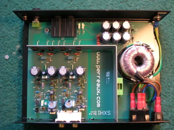 |
|
|
|
Post by smokeycigar on Nov 1, 2013 13:17:48 GMT
Interesting, does the shield need to be connected to earth?
Does it have to be tin, or can it be aluminum?
I've been thinking to remove the fuse holder, and install a chassis mount in the whole right next to the IEC plug (will need to be enlarged)
|
|
Deleted
Deleted Member
Posts: 0
|
Post by Deleted on Nov 1, 2013 13:58:22 GMT
I would assume a connection to chassis earth would be desirable. It's something I did in a diy head-amp/dac, whether it made any difference I couldn't say as I just popped it in from the start. On here somewhere....here we go;  I used thin steel, if it's earthed then you get the faraday cage effect so thickness then shouldn't be of importance? That would certainly aid easy fuse replacement but you'd probably want to open the case to find why the fuse had blown  |
|
|
|
Post by smokeycigar on Nov 1, 2013 14:09:08 GMT
Wow, that's a beautiful electronic mess  |
|
Deleted
Deleted Member
Posts: 0
|
Post by Deleted on Nov 1, 2013 22:27:28 GMT
|
|
|
|
Post by smokeycigar on Nov 2, 2013 5:10:53 GMT
On the other hand, might be easier to go down the external Power supply route. Same as used in MF X series.
Getting anything in the perreaux enclosure will be a pain.
Thoughts?
|
|
Deleted
Deleted Member
Posts: 0
|
Post by Deleted on Nov 2, 2013 5:29:43 GMT
On the other hand, might be easier to go down the external Power supply route. Same as used in MF X series. Getting anything in the perreaux enclosure will be a pain. Thoughts? Did you check the dimensions of the Altronics transformer that I linked to ? It should go awfully close to fitting in the same space as the existing transformer. Alex |
|
|
|
Post by smokeycigar on Nov 2, 2013 6:01:30 GMT
I did, the height is the issue, basically everything needs to be within 30mm. I'm a bit concerned about the cables from the transformer legs and the conductive body.
I did some more diagnosis:
Removed the transformer from the PCB
The secondaries do not have continuity with the screen. It seems that resistor next to the smoothing caps is connected through the black jumper to earth.
On the other hand the two primaries both show continuity with each other. All 4 connectors show continuity. As far as I know they two secondaries should be isolated and not show continuity. I'm using the diode mode on the MM, and am not getting an open circuit between the two primaries.
What is the purpose of the resistor connected to earth? It's connected to the center tap (0v) after the smoothing caps.
|
|
|
|
Post by smokeycigar on Nov 2, 2013 6:04:51 GMT
Anyone know If I can get a replacement tranny direct from Perraux?
I've tried contacting them earlier, but don't get any responses through the email.
I've fired then an email, lets see if they respond this time.
I should just try to see if the unit is functional with an externally fused Power Supply, hard wired directly to the PCB.
|
|
Deleted
Deleted Member
Posts: 0
|
Post by Deleted on Nov 2, 2013 6:45:49 GMT
Anyone know If I can get a replacement tranny direct from Perraux? I've tried contacting them earlier, but don't get any responses through the email. I've fired then an email, lets see if they respond this time. I should just try to see if the unit is functional with an externally fused Power Supply, hard wired directly to the PCB. All you would need to do is disconnect the secondary windings of the transformer, and feed in 12-0-12V AC from another transformer rated at 10VA or higher. into the bridge rectifier diodes. In my case I would simply feed in around + and -12V from my bench PSU. Regards Alex |
|
|
|
Post by smokeycigar on Nov 2, 2013 6:54:41 GMT
Yep, tranny is out alreasy and I can use the 12-0-12 80VA connected to my XCANs. I will need to route a separate earth though.
Wish I had a bench PS.
|
|
|
|
Post by smokeycigar on Nov 2, 2013 12:09:42 GMT
Update,
I hooked up a PS to the secondary section of the PCB. Fuse didn't blow, but I don't get the power led lighting up.
The polarity matters for the LED operation. Tested the power LED and it works.
I wasn't sure how to hook up the PS output to the PCB, am thinking I'll try to reverse it tomorrow and see if it lights up.
Does the polarity matter for the operation of the amplification section? (assuming it dose)
If not, then it implies that the amp section functions but just the LED is not wired correctly.
|
|
Deleted
Deleted Member
Posts: 0
|
Post by Deleted on Nov 2, 2013 12:36:58 GMT
Update, I hooked up a PS to the secondary section of the PCB. Fuse didn't blow, but I don't get the power led lighting up. The polarity matters for the LED operation. Tested the power LED and it works. I wasn't sure how to hook up the PS output to the PCB, am thinking I'll try to reverse it tomorrow and see if it lights up. Does the polarity matter for the operation of the amplification section? If not, then it implies that the amp section functions but just the LED is not wired correctly. smokeycigar Without seeing the schematic, I would expect that the external DC supply will be correctly steered by the 4 bridge rectifier diodes to the amplifier, no matter which way around the incoming + and -12V are connected. All you are doing is sending in +12, 0volts and -12v into the diodes, which will then output the correct polarity minus the voltage drop of the diodes themselves. I am surprised that the LED didn't light though. I presume that the 0volts line from your outboard PSU is connected to where the centre tap of the transformer secondary was connected ? Something doesn't sound quite right with this present set up. Regards Alex P.S. 11.45PM in Sydney, so Good night from Sydney Au. |
|
|
|
Post by smokeycigar on Nov 2, 2013 13:11:03 GMT
Alex, I'm in Sydney also But I'm a night owl. You can see the tracks of the PSU section in the second picture of my first post. The external supply is AC not DC. The center tap (0v) is correctly connected. (will double check again tomorrow) With the secondary polarity reversed I can assume that the LED will not function. (as it's wired directly to the secondaries before the diodes) Will play around with the polarity tomorrow, and am strongly predicting the LED will light up. If the amp actually functions is another thing. There was no explosions, fuse didn't blow and no odd smells... lets see what happens. |
|
|
|
Post by smokeycigar on Nov 2, 2013 13:20:48 GMT
|
|
Deleted
Deleted Member
Posts: 0
|
Post by Deleted on Nov 2, 2013 18:02:04 GMT
Seems to be some confusion on polarity? The secondaries should be fine either way around, being 12vac each. After the rectifier you then have your +12vdc and -12vdc. The LED is a separate issue being an AC type. Have you tried running the transformer isolated from the device? Do you get the 12vac for each secondary? Is the mains fuse a slow blow? The large resistor looks more like a 0.47ohm by my reckoning! (yellow, violet, silver, silver) Maybe the piccy below helps?  |
|
Deleted
Deleted Member
Posts: 0
|
Post by Deleted on Nov 2, 2013 19:34:03 GMT
I agree with Chris about the polarity confusion. Unless I am mistaken, the LED appears to be receiving half wave rectified D.C. via a series diode.
Assuming the incoming power is correctly connected, this suggests that either the diode is open circuit or arse about, or the LED which tests O.K. is connected the wrong way around. .
I think we have already established that there is an internal short circuit in the transformer between the screen and the secondary windings.
Regards
Alex
P.S.
I am also assuming that the yellow wire is connected only to the top of the diode, and clear of the earth track below.
|
|


