|
|
Post by bluerob on Apr 30, 2013 3:45:34 GMT
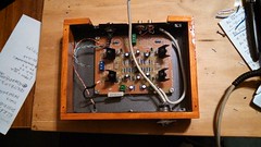
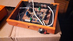
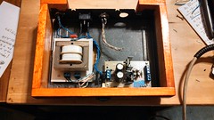
Finally I got to work on the SCHA and it is pretty much done and ready for an initial test. I followed much of the suggestions in the mods section. The things I did "different" were: -The caps near the transistors were soldered on top of the board, after looking for height clearance in the planed chassis the transistors and their heat-sinks had to be bent slightly anyways so the caps were not solder under the board as suggested. -The 47p caps in the center were replaced with higher quality than the ones supplied. -I replaced the 1watt resistors for smaller ones...I found the same value than the ones supplied but in a much smaller in size. -All electrolytics were replaced with panasonic FC´s -The 5171/1930´s that I could get are Fairchild no Toshibas but managed to make quite close pairs with them. -I ended using BC´s 550/560...funny thing is that I ordered C type of both and on the NPN set I got HFE around 600 but in the PNP batch they read in the 200´s so I ordered some B´s instead (C´s were out of stock) One pair read 291/293 and the other read 275/271....I hope that is close enough. The mayor change is that I´m going to try some Sanyo OSCON caps for the inputs and see how it goes with those pup's....in case I dont like them I´ll put some Wimas or some Polys. Well, cross your fingers chaps and hope it turns on LOL farm9.staticflickr.com/8121/8695064478_cd85ccb0fc_b.jpgfarm9.staticflickr.com/8115/8695064902_3d30cc67c5_b.jpgfarm9.staticflickr.com/8535/8695065560_f6c3361b3b_b.jpg |
|
Deleted
Deleted Member
Posts: 0
|
Post by Deleted on Apr 30, 2013 3:52:34 GMT
Hi
It's a funny thing about some of these small signal devices.
I needed HFEs of around 450 to 550 to complete my new 15W Class A PCBs, so I got 45 normal Philips BC549, not BC549C,
from Jaycar on Sunday. They all had HFE from 720 to 830, except for one which had an HFE of 1,048 !!!
Regards
Alex
|
|
|
|
Post by bluerob on Apr 30, 2013 4:03:57 GMT
I know matching devices could be a pain LOL. What I ended up doing was going to a small electronics shop here in town and took my time measuring each one and selecting them there rather than ordering "large" batches of them which turned out to be useless in my case.
|
|
|
|
Post by bluerob on Apr 30, 2013 21:45:27 GMT
Started the initial tests and found that on the outputs I have on one channel with 1.9v and on the other 1.6v using a dummy load of 68ohm per side and both inputs to ground.
I also measured the output voltage on the BB2134 pin1 and it reads 0.42v and on pin7 it measures 0.035v.
The above using the Jaykar PSU, rails read -14.85 and +15.07v
AFAIK no body has used output caps but here, it seems there is something wrong with the above voltages.
What do you guys recommend me to check in order to lower the voltages in the outputs?
Rob.
|
|
Deleted
Deleted Member
Posts: 0
|
Post by Deleted on Apr 30, 2013 22:04:57 GMT
Started the initial tests and found that on the outputs I have on one channel with 1.9v and on the other 1.6v using a dummy load of 68ohm per side and both inputs to ground. I also measured the output voltage on the BB2134 pin1 and it reads 0.42v and on pin7 it measures 0.035v. The above using the Jaykar PSU, rails read -14.85 and +15.07v AFAIK no body has used output caps but here, it seems there is something wrong with the above voltages. What do you guys recommend me to check in order to lower the voltages in the outputs? Rob. Rob There should be no more than a couple of mV at the outputs. Have you double checked all soldered joints in good lighting with a magnifying glass ? Are you using input capacitors? Are both LEDs of a similar brightness ? What are the voltages across each of the 100 ohm emitter resistors ? Alex |
|
|
|
Post by bluerob on Apr 30, 2013 23:32:43 GMT
Thanks Alex for the quick replay.
Yes I noticed a slight difference in brightness between the upper leds (closer to the inputs) compared with the bottom ones near the outputs. By looking at the color codes the emitter resistors are OK and if I recall correctly I did measure them prior soldering them.
The voltages on each rail seems fine, but when I measure the emmiter resistors as suggested a big difference is present, again the top ones near the inputs measure 1.22v each and the ones closer to the outputs measure 3.66/3.42v. Obviously here is something wrong all four should measure similarly AFAIK.
On the other hand I re-checked all solder points an found nothing obvious, no cold solders on sight or "bridges".
Yes, I have caps at the inputs, the OSCONS´s, but for the test I´m doing the inputs are "shorted" to ground.
Recheck, reconnected and same result...voltage at the outputs :/
|
|
Deleted
Deleted Member
Posts: 0
|
Post by Deleted on May 1, 2013 0:41:06 GMT
Thanks Alex for the quick replay. Yes I noticed a slight difference in brightness between the upper leds (closer to the inputs) compared with the bottom ones near the outputs. By looking at the color codes the emitter resistors are OK and if I recall correctly I did measure them prior soldering them. The voltages on each rail seems fine, but when I measure the emmiter resistors as suggested a big difference is present, again the top ones near the inputs measure 1.22v each and the ones closer to the outputs measure 3.66/3.42v. Obviously here is something wrong all four should measure similarly AFAIK. On the other hand I re-checked all solder points an found nothing obvious, no cold solders on sight or "bridges". Yes, I have caps at the inputs, the OSCONS´s, but for the test I´m doing the inputs are "shorted" to ground. Recheck, reconnected and same result...voltage at the outputs :/ You will need to check that all 4 x 100 ohm emitter resistors have approx. 1.2V or a little higher across them. The LEDs should have a forward voltage between 1.8V and 2V. The VBE of the BC547 and BC557 should be say 620mV or thereabouts, so the 100 ohm resistors should then have 2v less - 620mV, or between 1.2V and 1.4V across them. Double check that you have the correct type transistor at each of those 4 locations. Alex |
|
|
|
Post by bluerob on May 2, 2013 3:41:04 GMT
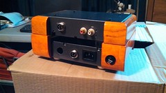
Well Alex, we (father and I...my dad being the DIY electronics guru of the family) went over it again and again, we check each resistor, polarity, solders, etc and everything seems fine...we even changed the bottom LEDs to make sure. The 100R emitter resistors close to the outputs have the 1.2v which seems fine but the bottom ones close to the inputs are measuring twice as much, over 3v. The VBE of the BC457(550 in my case) is higher also, around 1.2v but the forward voltage of the bottom LED´s seems fine, around 1.85. That being said we can only think of that the BC550´s are causing the voltage issue so we changed them... same results. Either we are missing something or the BC550 batch that I have is faulty or out of specs somehow. I´ll try to get some other transistors from a different store and see if that does the trick. If that does not work, well...we have no idea what is going on TBH. Just as reference here is a quick shot of the test setup. farm9.staticflickr.com/8545/8701127266_70cc7b24a3_b.jpg |
|
Deleted
Deleted Member
Posts: 0
|
Post by Deleted on May 2, 2013 3:56:44 GMT
Hi
There is no way that a BC550 should have a VBE of 1.2V ! Only a Darlington transistor , should have a VBE of around 1.2V.
If you don't know what a Darlington transistor is , it's basically 2 transistors with the collectors tied, and the emitter of the first one connected to the base of the second one.
In other words, 2 base junctions in series. If your DMM has a DIODE test function, try checking the bas to emitter voltage of one of those "BC550" transistors with it.
Regards
Alex
|
|
|
|
Post by bluerob on May 3, 2013 3:23:20 GMT
My bad, seems I was not checking VBE after a clear thought. Good news is that it now works, measured the output and on one channel reads 0.01mv and on the other 0.06 so everything seems fine now. The BC550´s were causing all the trouble for some unknown reason. I change them for BC548 and 58´s (paring them was easy this time).
I did noticed a hum noise on the left channel after a quick listen but the way the test was done left a lot room for improvement and things to check...flimsy jacks, lack of good grounds and I have to check that the source is not causing the hum noise.
BTW I see that there is a "Jack switch" on the board near the outputs...what is it? what does it do? when to use it? and how to wire it?
Rob.
|
|
Deleted
Deleted Member
Posts: 0
|
Post by Deleted on May 3, 2013 3:44:54 GMT
Hi Rob
The Jack Switch terminal is for operating relays in the Studio Series Preamplifier, for switching between RCA outputs and headphone amplifier.
This HA was designed as part of the Studio Series preamplifier, and was originally intended to be fitted inside the Studio Series Preamplifier,
although it can be used as a stand alone HA as we have done here.
Regards
Alex
|
|
|
|
Post by bluerob on May 4, 2013 2:15:12 GMT
I see, thank Alex for the info.
I was watching some SCHA pics of the finished projects around and noticed at least one of them with what it looks like having 2 PSUs. The only reason that I can think with my minimal knowledge is a mod to make the amp dual-mono?
|
|
Deleted
Deleted Member
Posts: 0
|
Post by Deleted on May 4, 2013 2:34:06 GMT
I see, thank Alex for the info. I was watching some SCHA pics of the finished projects around and noticed at least one of them with what it looks like having 2 PSUs. The only reason that I can think with my minimal knowledge is a mod to make the amp dual-mono? Rob I don't recollect that post, and I think it would be quite hard to make this PCB dual mono. The vast majority of the R.G. SC HA builds did however use an additional PCB in the form of the JLH PSU Add-on. (A.K.A. JLH "Ripple Eater" ) Regards Alex |
|
|
|
Post by bluerob on May 4, 2013 4:35:04 GMT
Here, this is the one I was thinking of i273.photobucket.com/albums/jj220/kingbusoms/088.jpg...Leo hope you don't mind me borrowing you pic  I though there were two PSUs stacked but maybe is the ripple eater as you mentioned (I got my JLH boards today BTW  ) Thanks Again Alex...sorry to be a PITA LOL |
|
Deleted
Deleted Member
Posts: 0
|
Post by Deleted on May 4, 2013 8:48:01 GMT
Here, this is the one I was thinking of i273.photobucket.com/albums/jj220/kingbusoms/088.jpg...Leo hope you don't mind me borrowing you pic I though there were two PSUs stacked but maybe is the ripple eater as you mentioned (I got my JLH boards today BTW ) Thanks Again Alex...sorry to be a PITA LOL Rob I think the other PCB in Leo's photo is likely to be an older version JLH. If you have any PCB pins of a suitable diameter, I would recommend fitting them where you currently have the resistors across the original Zobel coils location. This will allow you to fit different value resistors there to best suit the headphones that you are using. 68 ohms is usually a good compromise to start with. I would experiment with different values there after you get the JLH installed and burned in. Regards Alex |
|
|
|
Post by bluerob on May 11, 2013 4:34:19 GMT
Got it Alex, for the resistors you mention in the output I think I used 47R for starters.
Talking about the JHL I´m about to start with it and going through the schematic and BOM I noticed there are a couple of options regarding the resistors for the current limiter section and have a pair of question on the matter.
-What is the current draw of the SCHA with mods?
I ask since I assume the JHL current limiter should be in accordance to the above.
-Can you confirm please if the resistors on the modded JHL are correct and up to date with the latest mods:
R11/R111 = 1K8
R12/R112 = 1R2
R13/R113 = 2K7
And most important of all....do I have to reverse the polarity of diodes and caps plus switching some of the 2SA1930-2SC5171 and vice versa? I saw this somewhere around, I recall it was a tutorial of some sort regarding the JHL, I´m unsure if I have to go through those procedures since my JHL boards are newer (Black Version), both +/- are in the same board vs the previous version ones that were on separate boards (the ones used in the tutorial document), do not know for sure if the board I have is now corrected and I can skip the switching and flipping...hope my question makes sence LOL.
Rob.
|
|
Deleted
Deleted Member
Posts: 0
|
Post by Deleted on May 11, 2013 5:08:53 GMT
Hi Rob With the JLH for the SC HA the current limiter section is not used. That means you don't need to fit the diodes, 2SA1930 and 2SC5171, 1.8K , 1 ohm emitter resistor etc. at the power input end of the PCB. You can also use a 4,700uF 10v low ESR capacitor in parallel with a normal 4,700uF 16V for both halves of the PCB, with a further small improvement at the very low end over the 2,200uF electros. The capacitor polarities are as marked on this PCB from Greg. 2 x 2SC5171, BC639 and 2 x BC550C are used for the +VE output side and 2 x 2SA1930,BC640 and 2 x BC560C for the -VE output side, Just connect a short strap between the outer vacant holes left by R12/R112 and the nearby vacant hole between R12 and R1, and R101 and R112. This will bypass the CL section. Give it 48 hours of use for the large capacitors to fully form, as SQ will vary tremendously until they do. Fit small heatsinks to the 2SA1930 and 2SC5171 with the 33 ohm emitter resistors, as they sometimes get quite warm until the capacitors are fully formed.. Regards Alex users.tpg.com.au/gerskine/greg/default.htm Click on Power Supplies. |
|
|
|
Post by bluerob on May 11, 2013 8:13:24 GMT
|
|
|
|
Post by bluerob on May 11, 2013 14:10:19 GMT
... and I still don't get the right way to paste pics around here LOL
|
|
Deleted
Deleted Member
Posts: 0
|
Post by Deleted on May 11, 2013 14:21:50 GMT
You've basically got it right on the posting of photos. All you need to change is make sure you paste in the code for full size image rather than the "thumbnail".
I'm assuming your cases are small valve amp jobbies? Look nice.
|
|
|
|
Post by bluerob on May 11, 2013 18:15:31 GMT
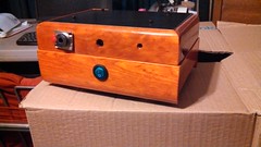
You've basically got it right on the posting of photos. All you need to change is make sure you paste in the code for full size image rather than the "thumbnail". I'm assuming your cases are small valve amp jobbies? Look nice. Thanks CJ for the hint. No the cases are made of old CD drive enclosures, drilled, primed, painted and sealed with a wood trim on the outside with some stain, sealer and lacker. I was going to go the obvious way by using aluminum but ended up recycling the cases instead. I know is not the best way to go but it serves its purpose for the time being.  |
|
|
|
Post by bluerob on May 12, 2013 21:43:57 GMT
Quick question about matching transistors in the JLH the 2sc5171 and 2sa1930 that is...how important is this in the board?
I have good pairs of each, two 5171 with Hfe of 184 for example and two 1930 of hfe of 173...my doubt is that if pairing should be among equals or I must match 4 ways sort to speak, where all four are close to each other?
Rob
|
|
Deleted
Deleted Member
Posts: 0
|
Post by Deleted on May 12, 2013 22:02:12 GMT
Quick question about matching transistors in the JLH the 2sc5171 and 2sa1930 that is...how important is this in the board? I have good pairs of each, two 5171 with Hfe of 184 for example and two 1930 of hfe of 173...my doubt is that if pairing should be among equals or I must match 4 ways sort to speak, where all four are close to each other? Rob Hi Rob If the pairs are reasonably close in HFE, as they usually are, I wouldn't worry about it . I try to match the BC550c and BC560C fairly closely though, as I heard an improvement from doing that, and adding a 2.7K collector resistor that wasn't present in the original John Linsley Hood design. You don't need to match the BC550C and BC560C pairs to each other though. Kind Regards Alex |
|
|
|
Post by bluerob on May 12, 2013 22:30:00 GMT
Awesome Alex and just in time...you see my soldering station is hot and ready LoL.
I did match the 550s/60s tho in my case I ended up using 547/57b's do to my recent problem with my 550c batch and lack of availability around here. Hope this change does not degrade much the output.
Cheers,
Rob
|
|
Deleted
Deleted Member
Posts: 0
|
Post by Deleted on May 12, 2013 22:44:06 GMT
Awesome Alex and just in time...you see my soldering station is hot and ready LoL. I did match the 550s/60s tho in my case I ended up using 547/57b's do to my recent problem with my 550c batch and lack of availability around here. Hope this change does not degrade much the output. Cheers, Rob Rob You need to have high HFE devices in that area. As the voltage there is only + and -15V, other suitable devices will be high gain ( as measured) BC547,548 and 549See if you can find some with HFE of 400 or higher. Regards Alex |
|


 )
)