|
|
Post by dicky on Sept 11, 2012 5:32:32 GMT
The battery is 12v. The heater requirement for this tube is 6.3v @ 0.3A so ~20 ohm is optimal here (for the tube). However, it seems to sound that better with a higher heater voltage (~8v with 10 ohms). This may, of course, reduce tube life?!
|
|
Deleted
Deleted Member
Posts: 0
|
Post by Deleted on Sept 11, 2012 6:24:07 GMT
The battery is 12v. The heater requirement for this tube is 6.3v @ 0.3A so ~20 ohm is optimal here (for the tube). However, it seems to sound that better with a higher heater voltage (~8v with 10 ohms). This may, of course, reduce tube life?! I hope you have spare tubes !  |
|
|
|
Post by dicky on Sept 11, 2012 6:42:48 GMT
As it happens, I do.  I am experimenting with different resistor values to find the best compromise in heater voltage and SQ. If I don't get anywhere - it's an £18 paperweight.  |
|
mrarroyo
Been here a while!  Our man in Miami!
Posts: 1,003
|
Post by mrarroyo on Sept 11, 2012 9:58:25 GMT
solderdude does that mean I should not op-amps? I was thinking of the LM4562 and AD797.
|
|
Deleted
Deleted Member
Posts: 0
|
Post by Deleted on Sept 11, 2012 14:08:29 GMT
....rising up to 4.5 hours charge time. Sounds like it is worth modding if you already have one but maybe not worth buying to mod, when you could just get a better SQ and battery life SS CMoy in the first place?
|
|
Deleted
Deleted Member
Posts: 0
|
Post by Deleted on Sept 11, 2012 16:12:41 GMT
solderdude does that mean I should not op-amps? I was thinking of the LM4562 and AD797. Just pop 'm in and see if it works. Fast opamps MAY oscillate and you may or may not notice this depending on frequency and severity of the oscillation. |
|
Deleted
Deleted Member
Posts: 0
|
Post by Deleted on Sept 11, 2012 16:13:44 GMT
The battery is 12v. The heater requirement for this tube is 6.3v @ 0.3A so ~20 ohm is optimal here (for the tube). However, it seems to sound that better with a higher heater voltage (~8v with 10 ohms). This may, of course, reduce tube life?! Can you measure the actual tube heater voltage and voltage across the 10 Ohm ? |
|
|
|
Post by dicky on Sept 11, 2012 16:37:28 GMT
Hi Frans. With 11 ohms (currently). I measure 3.7v across the resistor and 8.2v on the heater - way too much. I'm going to pop a 20 ohm resistor in which should give me around 6.4v on the heater.
|
|
|
|
Post by dicky on Sept 11, 2012 16:43:27 GMT
Tube spec is 6.3 to 6.6v.
|
|
|
|
Post by dicky on Sept 11, 2012 18:45:54 GMT
I just plonked a 20 ohm resistor in and I get exactly 6.3v on the heater.
|
|
Deleted
Deleted Member
Posts: 0
|
Post by Deleted on Sept 11, 2012 18:48:16 GMT
It's strange how the manufacturer sets the heater voltage that high himself.
They use 11 or 10 Ohm.
The heater current is now 375mA !
a 4.5W drawing heater, no wonder it get's HOT.
I figure the emission is much higher at a higher heater voltage and is needed for the circuit itself (the actual tube setting) to work correctly.
If you can make a picture of the PCB, the side with the traces on it and clear enough so they can be followed I can draw the schematics and suggest improvements.
Miguels picture of the bottom doesn't show the traces.
|
|
layums
100+
Thank you for the untips
Just started electrical fixing, to go with my other fixing bad habits :)
Posts: 111
|
Post by layums on Sept 11, 2012 19:31:53 GMT
Love it Frans. Awesome how people get involved on this forum. What's this.....it's ok......but do this and it's better........that's skill!
I had my eye on one of these portables too. Would be good to hear from people after they have had it for a whole to hear how it sounds.
Traditional smooth tube, or glowing gimmick of tube and nothing special.
|
|
|
|
Post by dicky on Sept 11, 2012 19:57:38 GMT
I'll have a go at taking a picture tomorrow in daylight. It's too dark now and if I use flash it'll just blow out any detail. The traces are difficult enough to see anyway! Actually, I might try it on a scanner.
Do you need another image of the top of the board too?
|
|
Deleted
Deleted Member
Posts: 0
|
Post by Deleted on Sept 11, 2012 20:10:41 GMT
Miguels top board pics are more than O.K.
Good enough colour rendition/sharpness to discriminate between color bands.
Perhaps some values of parts that are not visible when I have the schematics extracted.
It's a very simple schematic and can draw a schematic already based on the used parts and how I think it will be made but like to be sure when posting it.
|
|
Deleted
Deleted Member
Posts: 0
|
Post by Deleted on Sept 11, 2012 22:26:17 GMT
solderdude does that mean I should not op-amps? I was thinking of the LM4562 and AD797. Just pop 'm in and see if it works. Fast opamps MAY oscillate and you may or may not notice this depending on frequency and severity of the oscillation. Miguel Also check that the replacement I.C. doesn't get quite warm or even hot.That can often happen if it is oscillating at a very high frequency. Regards Alex |
|
mrarroyo
Been here a while!
Our man in Miami!
Posts: 1,003
|
Post by mrarroyo on Sept 12, 2012 10:43:32 GMT
Will do over the weekend, thanks.
|
|
|
|
Post by dicky on Sept 12, 2012 16:44:24 GMT
Hi Frans, I hope this useful. I've drawn the less obvious traces in green. If you want me to do the rest for clarity then let me know. There are some traces on the top of the board too I think. Attachments:
|
|
Deleted
Deleted Member
Posts: 0
|
Post by Deleted on Sept 12, 2012 17:40:57 GMT
I a, missing some traces and suspect they are on the top side it appears to be a double sided board.
Any chance you can find a way to make a similar pic on the top side with the traces drawn like on the pic you posted ?
|
|
mrarroyo
Been here a while!
Our man in Miami!
Posts: 1,003
|
Post by mrarroyo on Sept 13, 2012 9:59:27 GMT
I have now about 9 hours of use on this amp, it is on the warm side and unless you compare it directly to top portable amps it is quite enjoyable. So far I have been using low impedance cans like the Creative Live Aurvana and the Samson SR850. I do wish the battery lasted more than 3 hours so I hope someone can figure a way to make it happen. Thanks.
|
|
|
|
Post by dicky on Sept 13, 2012 10:32:01 GMT
Miguel, I'm using a 1000mAh RC battery instead of the supplied battery to get longer listening time. If you replace your 10 ohm heater resistor with 20 ohms it'll last longer and run cooler. I'll post a picture of the top of the board tonight. Maybe Frans can come up with some magic.  |
|
Deleted
Deleted Member
Posts: 0
|
Post by Deleted on Sept 13, 2012 11:14:09 GMT
I have now about 9 hours of use on this amp, it is on the warm side and unless you compare it directly to top portable amps it is quite enjoyable. So far I have been using low impedance cans like the Creative Live Aurvana and the Samson SR850. I do wish the battery lasted more than 3 hours so I hope someone can figure a way to make it happen. Thanks. Miguel Back to the future ? ;D Perhaps even a 12V 7AH SLA battery ? Attachments:
|
|
|
|
Post by PinkFloyd on Sept 13, 2012 12:13:32 GMT
The way to go for the hardcore enthusiast? 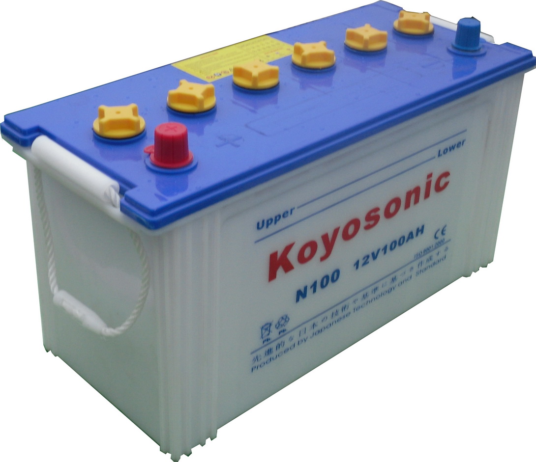 You'd need one of these to make it "portable".....  You should get a good few months of play time though Miguel |
|
Deleted
Deleted Member
Posts: 0
|
Post by Deleted on Sept 13, 2012 14:29:51 GMT
On a more serious note. You cannot escape from the heater itself which draws 95% of all the power. Even when powered with 5.5V (that's 20% below nominal and as low as you can get without sacrificing emission) you still end up with a lot of current/consumed power. You can lower the total power consumption of this amp by about 40% (that's a considerable gain in playing time) by feeding the heater from a TSR 1-2465 regulator (the same as used in the Indeed G2 mod) with the needed extra parts. An extra 1N4001 in series with the output of the TSR will give just under 6V on the tube. Good lifespan and enough emission and stable even when the battery voltage drops. When accidentally left on (as it is now) the heater will completely discharge, and thereby destroy, the battery. With the TSR the bonus is the heater is switched off below 9V battery voltage. Furthermore I would replace the 2 resistors (10k = brown, black, black, red, brown) with 20k pots. This way you can 'set' the output voltage of the opamp (+ of the 1000uF caps) to 6V or close to it for max SQ. At least I think that will be the case. Both these resistors are situated under the tube. Also I would mount 2 decoupling caps directly between pin 8 and 4 of the opamp with as short as possible wiring. One of them 10uF electro and the other one 10nF (to 100nF) ceramic multilayer. That's about it.... And the 100A traction battery from Mike will give you approx 500 hrs of listening pleasure, you can even power the player with that battery ! Unmodded I reckon about 300 hours.. still not bad . |
|
|
|
Post by dicky on Sept 13, 2012 18:19:56 GMT
Hi Frans, here's a top view of the board with the traces marked. (I don't think there are any more.) Let me know if you need any other views. Attachments:
|
|
Deleted
Deleted Member
Posts: 0
|
Post by Deleted on Sept 13, 2012 18:55:47 GMT
The underside of the small tube PCB would make it complete to verify what I think the schematic looks like.
|
|