|
|
Post by hexaddikt on Jun 23, 2011 9:03:26 GMT
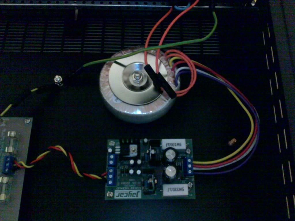
Hi all, I've never wired up 240V before so I'm asking that someone check to see if anything is completely wrong. I've read up on a lot of information in the forum on how it should be done so hopefully it should be correct. All exposed parts will have heat-shrink tubing covering them. Please excuse the horrible photos. I'll take more photos if needed. A question too, all of the side panels except the front and back have a bolt (you can see this in the first photo). Is this for Earth? And if so should each of these be connected to the Earth wiring from the mains? 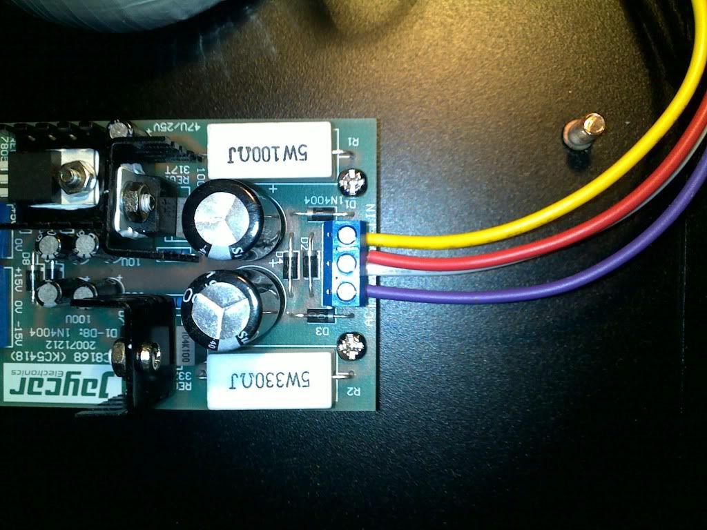 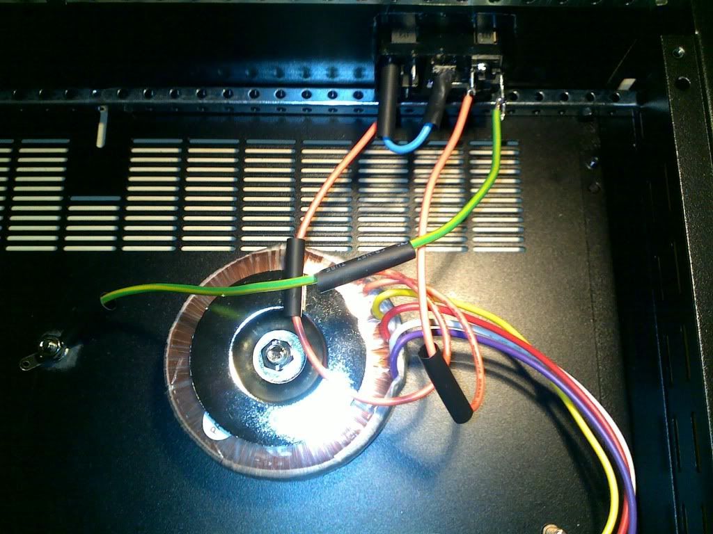 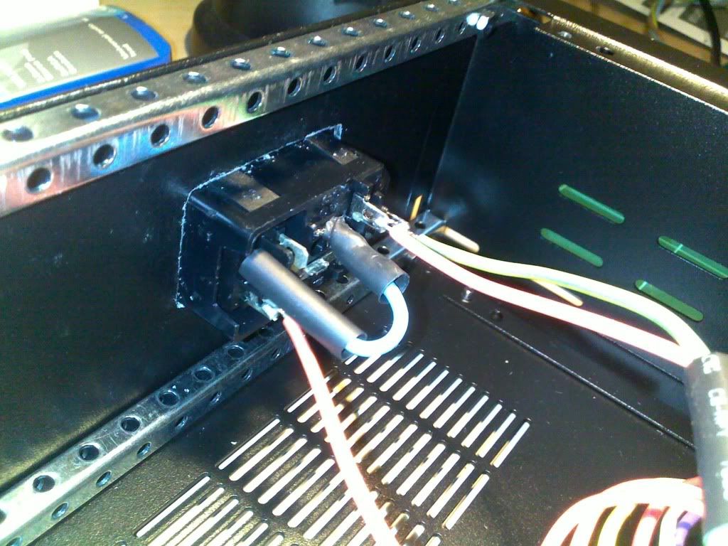 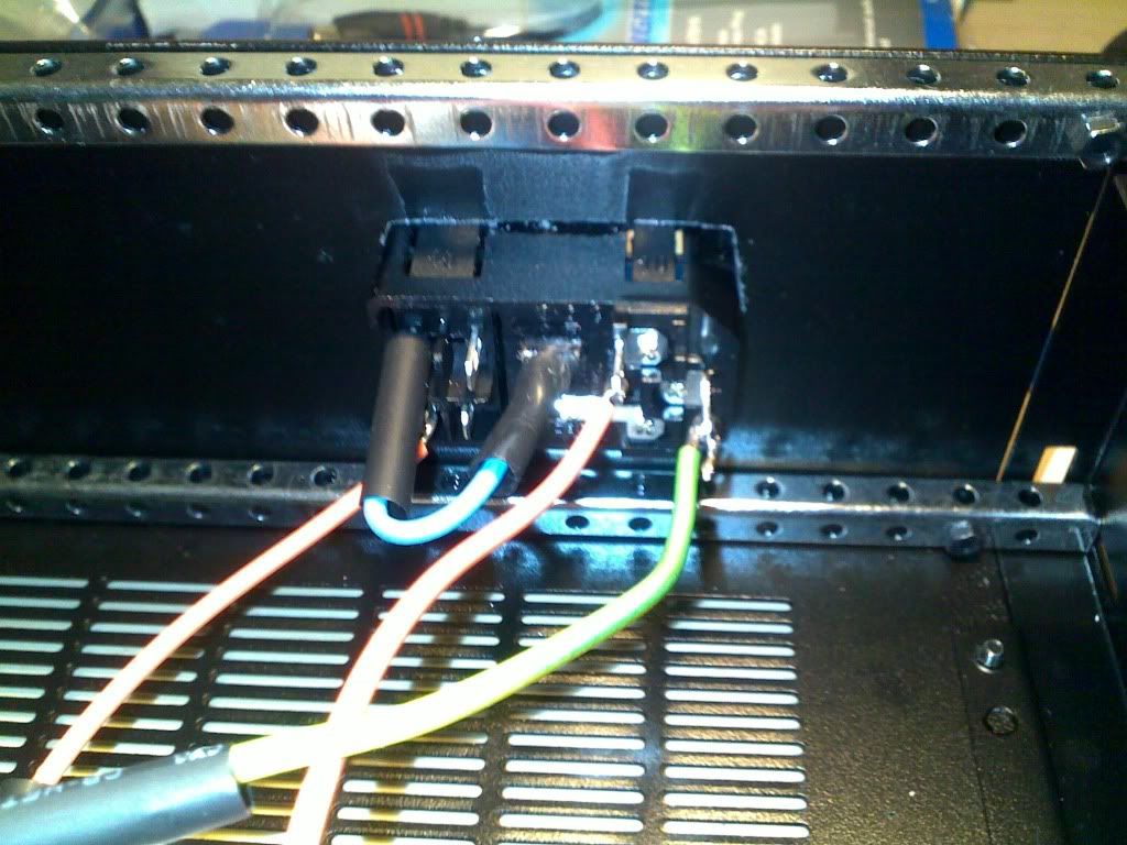 |
|
Deleted
Deleted Member
Posts: 0
|
Post by Deleted on Jun 23, 2011 9:46:55 GMT
hexaddikt
Do you have catalogue numbers for the IEC socket and transformer ?
Alex
|
|
|
|
Post by hexaddikt on Jun 23, 2011 10:18:28 GMT
Hi Alex, the IEC socket is PP4003 and the transformer is MT2086. Both are from Jaycar.
|
|
Deleted
Deleted Member
Posts: 0
|
Post by Deleted on Jun 23, 2011 10:54:45 GMT
Hi Alex, the IEC socket is PP4003 and the transformer is MT2086. Both are from Jaycar. The transformer secondary connections are correct. I can't verify the switched IEC socket connections as I have no experience of that particular socket, and the Jaycar page does not show the rear or connections. Perhaps someone else has experience with this type of IEC socket ? Alex |
|
|
|
Post by hexaddikt on Jun 23, 2011 11:38:23 GMT
Thanks Alex. If it helps, here is a painfully awful drawing of the back of the IEC plug that I will be ashamed of for the rest of my life. On the other side of section A is the switch. When the switch is "off" there is no connectivity between the orange wire coming from section A and blue wire. When the switch is in the "on" position there is connectivity between the blue and orange wire from section A and orange wire from section B. There is no connectivity between Earth and any of the other wires ever. The red line is the fuse inside the IEC plug. The orange "T" means the transformer. 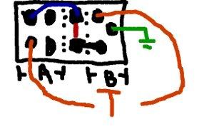 Hope it makes sense. |
|
Deleted
Deleted Member
Posts: 0
|
Post by Deleted on Jun 23, 2011 12:15:18 GMT
Thanks Alex. If it helps, here is a painfully awful drawing of the back of the IEC plug that I will be ashamed of for the rest of my life. On the other side of section A is the switch. When the switch is "off" there is no connectivity between the orange wire coming from section A and blue wire. When the switch is in the "on" position there is connectivity between the blue and orange wire from section A and orange wire from section B. There is no connectivity between Earth and any of the other wires ever. The red line is the fuse inside the IEC plug. The orange "T" means the transformer. Hope it makes sense. It does appear to be correct, but I wouldn't bet my life or anybody else's life on it.  I suggest that you disconnect the 2 wires to the transformer, and using a DMM on the AC scale, check (carefully !) for 240VAC where the wires were connnected,but with switch in the off position and the on position. Remove the plug from the socket , followed by the fuse being removed. Plug in the mains lead again and ensure that there is no AC measured at the connection points.If both the switch and the fuse remove mains voltage from the connection points, then reconnect the transformer primary leads again, and check for a little over 30V AC at the outer terminals of the PSU terminal block when powered up. Remember that 240VAC is dangerous, and should be treated with respect. Slip those insulating pieces over the exposed mains terminals when you are satisfied that all is correct. Alex |
|
|
|
Post by hexaddikt on Jun 23, 2011 12:39:42 GMT
Thanks, I'll try that. Do you also know what the bolts are for on the enclosure?
|
|
|
|
Post by hexaddikt on Jun 23, 2011 13:44:49 GMT
Well that put a stop to things. While trying what you suggested I found out that the IEC socket doesn't come with a fuse. I'll have to pick one up tomorrow at Jaycar.
|
|
|
|
Post by hexaddikt on Jun 24, 2011 5:15:31 GMT
Okay, so I've bought the fuse needed and ran the tests. Everything seems good. All measurements are within the +/- 5% recommended tolerance so I'm moving on to installing the amp.
When the switch is on:
IN:
33VAC
OUT:
+15-0: 15.04V
-15-0: -15.3V
+5-0: 5.04V
-15-+15: 30.4V
When the switch is off:
IN:
0VAC
OUT:
+15-0: 0.013V
-15-0: 0V
+5-0: 0V
-15-+15: 0.007V
I take it the small voltage out when the switch is off is from the capacitors having not discharged.
Thanks for your help Alex.
|
|
Deleted
Deleted Member
Posts: 0
|
Post by Deleted on Jun 24, 2011 5:53:26 GMT
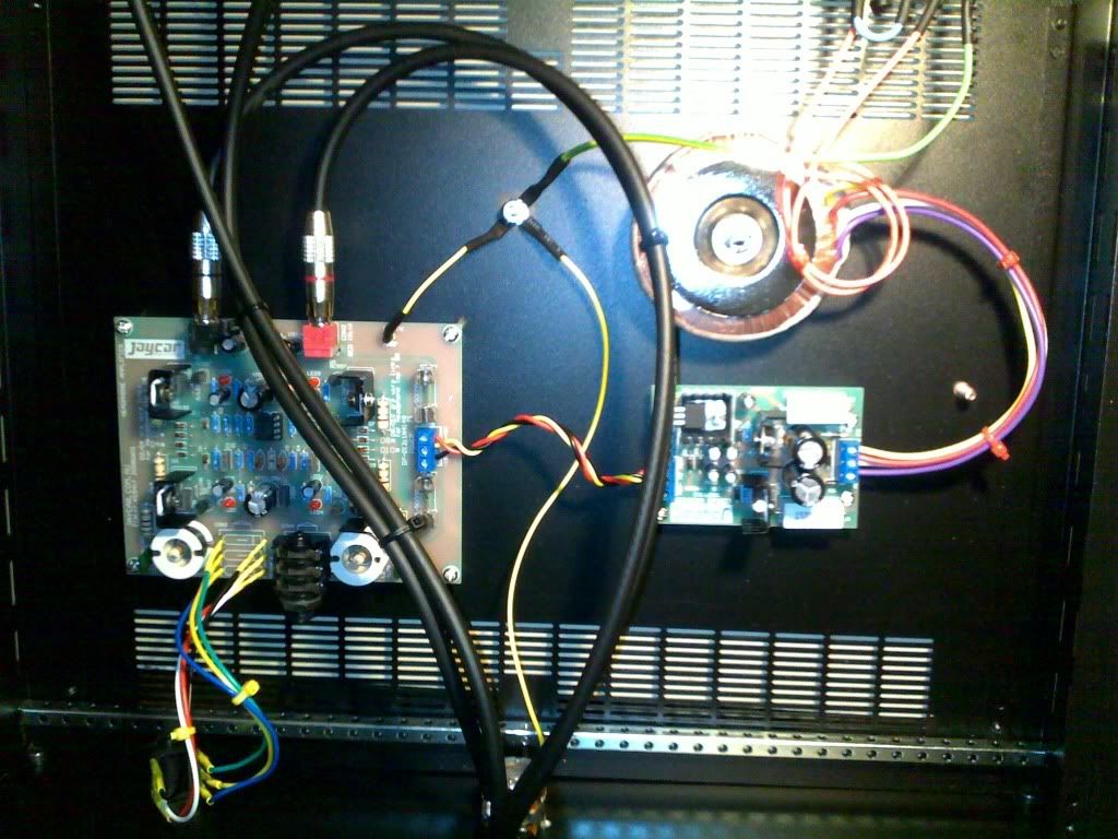
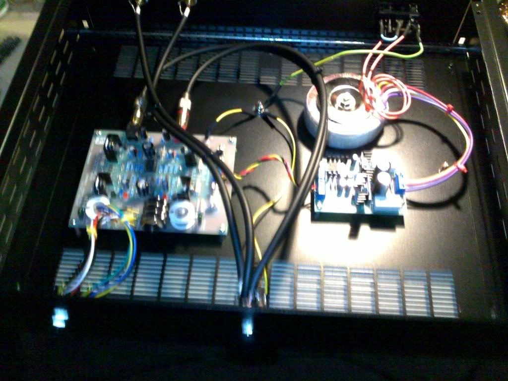
hexaddikt Seems like you are good to go. Just make sure you use suitably chosen hookup wire colours when you connect the PSU to the HA. Green or yellow is good for earth, and orange or red for positive. Black, white, or blue is good for negative. Choosing colour coded wires that you can relate to, makes checking and further changes less likely to cause heartbreak. Alex |
|
|
|
Post by hexaddikt on Jun 24, 2011 17:58:13 GMT
|
|
Deleted
Deleted Member
Posts: 0
|
Post by Deleted on Jun 24, 2011 22:46:47 GMT
|
|
|
|
Post by hexaddikt on Jun 26, 2011 3:51:36 GMT
Alex
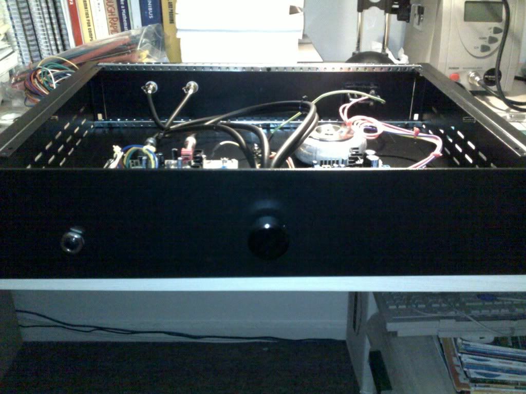
It was incredibly exciting when all LEDs lit up the first time when I powered on the amp. I don't think my wife understood why I was so happy!
And yes, I've had my eye on that thread for the last year or so and I'm really interested in trying some out. I'll have to get a decent pair of headphones first though, at the moment I've only got phones from mp3 players :/
Joshua
|
|
Deleted
Deleted Member
Posts: 0
|
Post by Deleted on Jun 26, 2011 7:17:28 GMT
Joshua
Only if you decide to go the whole route, send me a PM.
At this point in time I still have a couple of JLH PCBs left.
Free to Aussies only, as the cost of OS postage would be far more than they are worth. I want to make sure that the remaining few actually get used.
You would need to source the bits yourself from the B.O.M.though.
Regards
Alex
P.S.
In the mean time, I suggest you modify the PSU as per the Tweaks Thread. It will then run cooler and have more current in reserve.
|
|