Deleted
Deleted Member
Posts: 0
|
Post by Deleted on Aug 22, 2010 21:36:55 GMT
Don`t worry claus, I will be in exactly the same boat as you building this and i have not even seen the parts yet  should be fun though ;D just going to check my house insurance to make sure i have adequate cover for when i switch it on for the first, and possibly the last time  Mick. Mick...... We will take it slow and start off by populating the resistors..... follow the guide and you will have an amp that fires up "first" time (assuming your soldering skills are good). Mike. Yes i am happy with my soldering now Mike, its just like claus has said, making sure polarity is right, and the right bits go in the correct places on the board, but i have followed your guidance before and so far so good, if i dont give it a try, i will never learn will i!!!! looking forward to it   |
|
|
|
Post by PinkFloyd on Aug 24, 2010 14:53:02 GMT
Claus,
The 1500 resistors (1.5K) the BIG ones must be fitted on the longer resistor slots (wider pitch).... the smaller ones go on the smaller slots.
|
|
|
|
Post by PinkFloyd on Aug 24, 2010 20:46:38 GMT
I'm just in from the workshop..... went out for "half an hour" to populate the resistors and two hours later I've almost completed the entire amp  I started speeding up and was working as if I was on a production line and was getting "paid" for each component  An absolutely SIMPLE amp to put together, you really don't need instructions as the PCB and parts are clearly marked. As long as you fit the caps, diodes, transistors and trimpots the right way round this puppy should fire up first time! A few tips: Fit the heatsinks first and then drop the transistors in, tighten them up and then solder them. Make sure the cap polarity is correct + is the longer leg and - is the shorter leg. Minus is also denoted by a band that runs down the side of the capacitor. Make sure to fit the "fat" resistors in the correct places.... the longer pitched resistor slots means "fat ones go here". With the diodes, the black band should be here I < (the other side of the arrow). Start polulating the surface level parts first.... this is the best way to do it..... ie: don't start off fitting all the big stuff or you may find it tricky fitting the small parts in between them. Common sense I know but it's amazing the amount of people who start populating the "eye candy" parts first. Nothing more I can think of, take your time and match the parts up to the board. I was sent about 40 spare transistors for some reason.... not complaining tho'  The light was terrible outside so I'll take some close ups of the finished article tomorrow.... should take me about half an hour to complete it. Here are a few crummy shots to be getting on with. I fitted a wrong type cap (should have been a green MUSE) and will rectify that tomorrow. Another slight change.... I have omitted the 100nF WIMA bypass caps.... these bypass the 3300uF ELNA electrolytics..... instead, I have fitted 3.3uF WIMA film caps here instead.... just seems a better ratio to me. I will also be omitting the 1N4001 diodes and will fit UF4001 here instead and will probably shunt them with 47nF Mylar film caps. 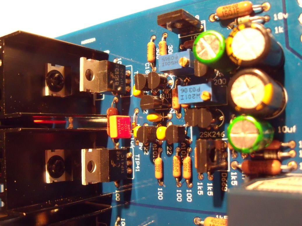 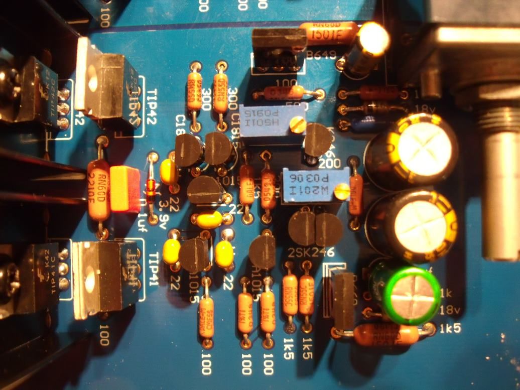 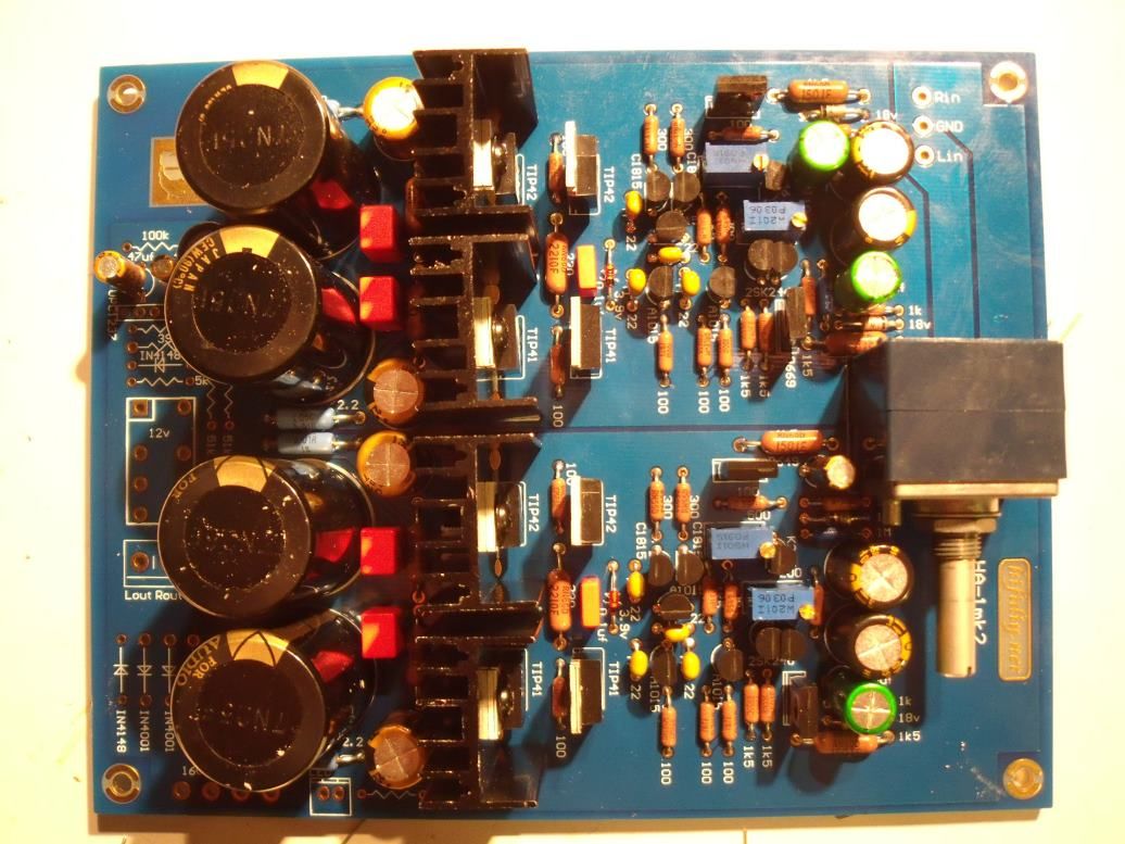 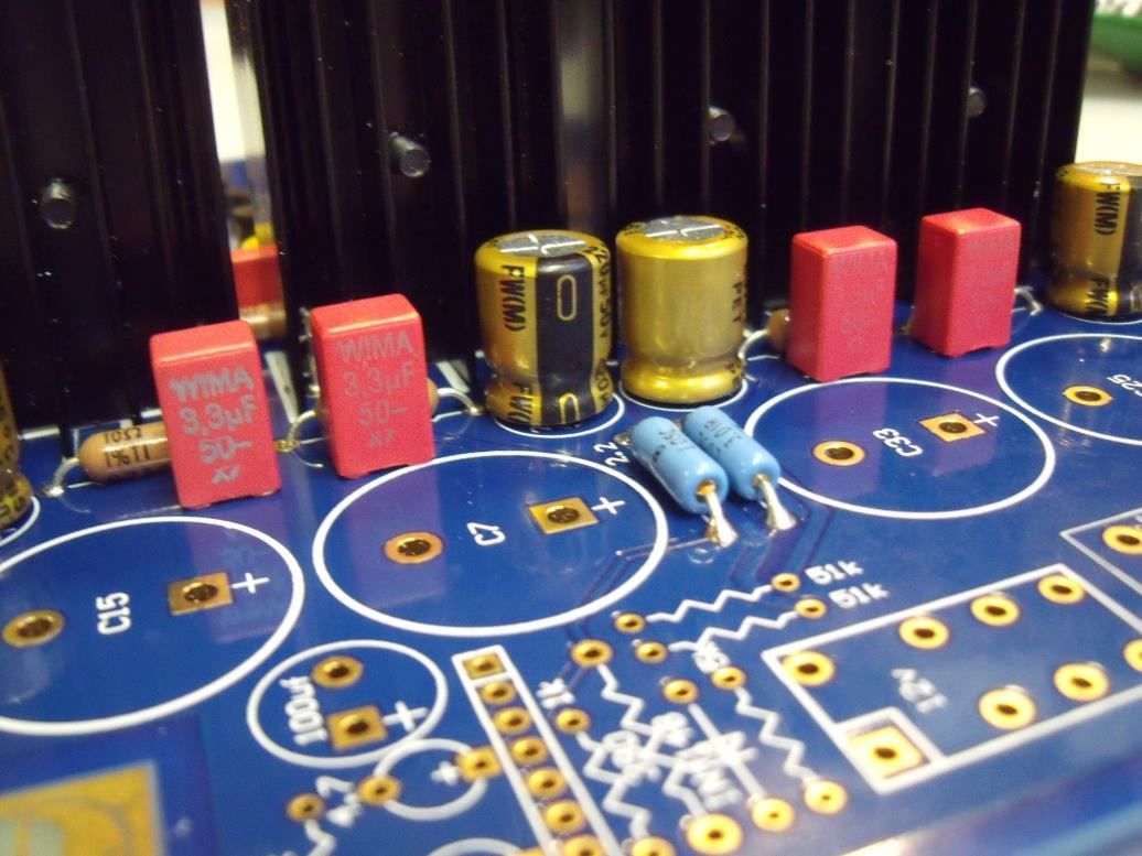 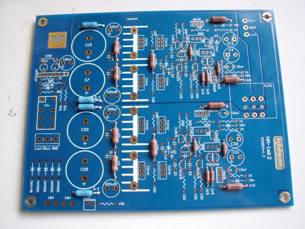 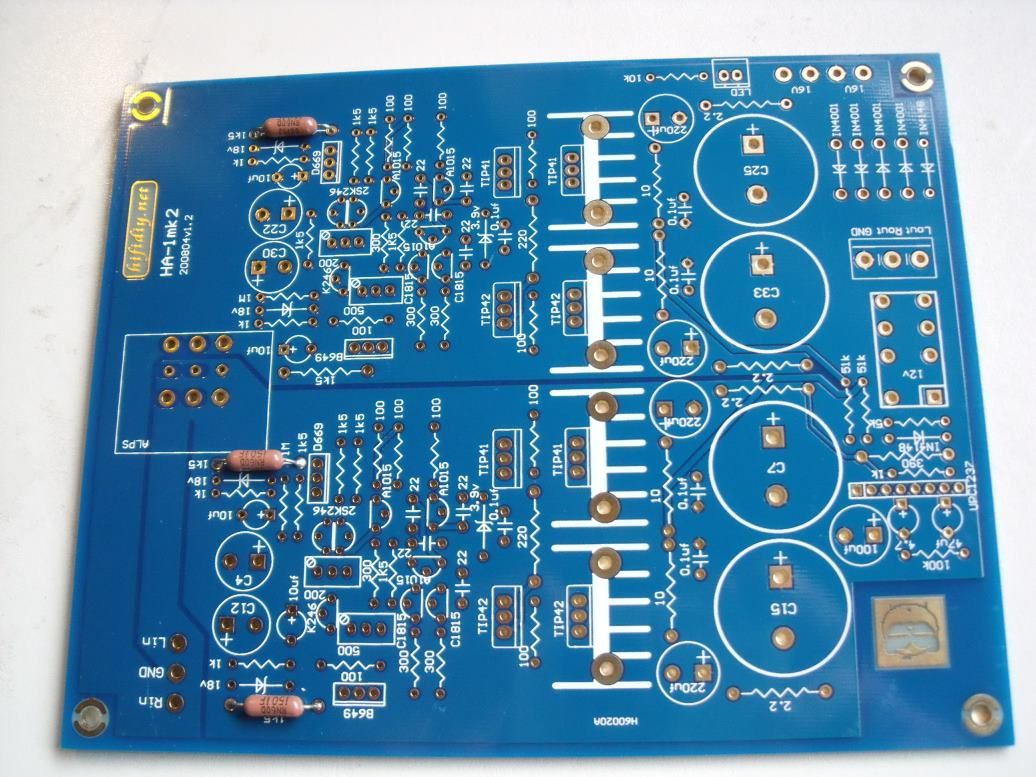 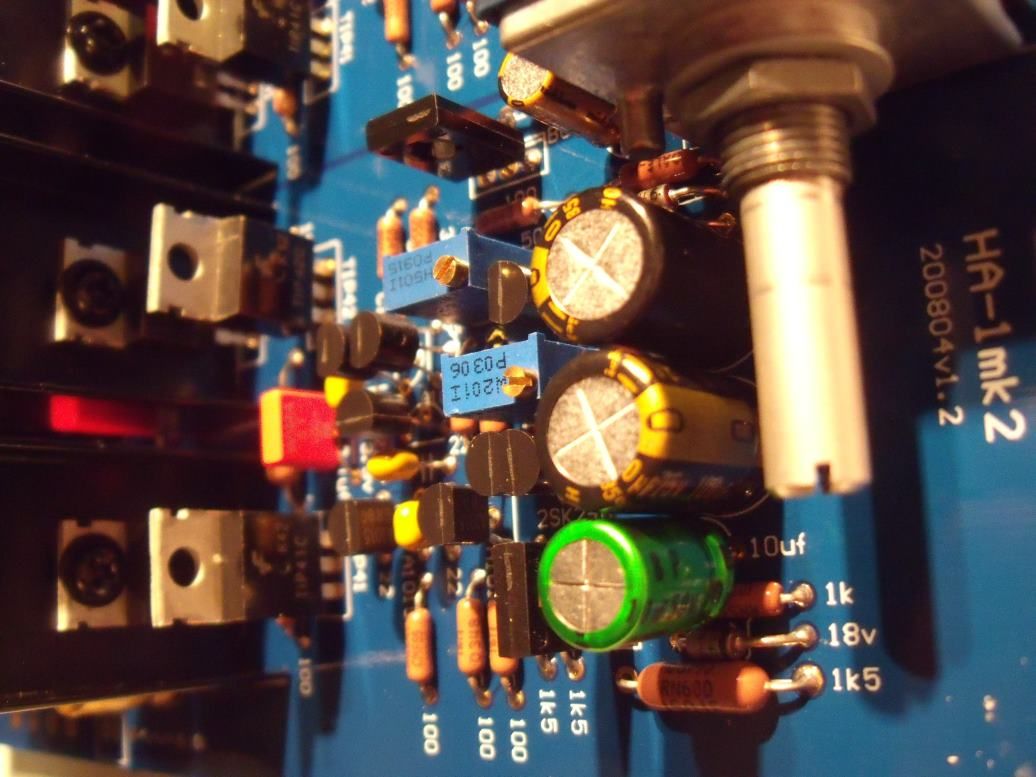 |
|
|
|
Post by PinkFloyd on Aug 24, 2010 21:28:17 GMT
Another thing I got four blue resistors, the ones right beside the big caps, the board says 2,2, but they messure 3,0 would that be a problem ??, it is the only resistors I got left and they do not fit anywhere else HELP 3 is as good as 2 in this position.... YES, fit the 4 x 3ohm blue resistors. Yep, I too got this random 10uF cap.... bin it. You will need a 100uF (35V / preferably 50V)..... have another look at the parts.... you should have a gold coloured "Nichicon" 100uf Cap? If not, it's missing.... no biggie.... if you have any 100uF caps (or 220uF / 470uF) kicking about then fit one in this position..... if not I can send you one, no probs. On the board you will see two slots marked "500" and two slots marked "200". You have two trimpots marked "201" and two marked "501" (forget the rest of the markings) Fit the 201 trimpots to the 200 PCB slots and fit the 501 trimpots to the 500 PCB slots. Just be sure to fit them the correct way round, they are not omni directional.... the black band on the diode should be to the left of the arrow "<" on the PCB. The flat side with the circle on it goes toward the 1N4007 diode direction.... the side with the text on it faces the adjacent 4.7uF / 47uF / 100uF capacitors..... The "FAT" 1500ohm resistors go to the wider pitch 1K5 slots on the board..... 1500ohm = 1K5. Hope this helps. |
|
|
|
Post by clausdk on Aug 24, 2010 21:47:15 GMT
Another thing I got four blue resistors, the ones right beside the big caps, the board says 2,2, but they messure 3,0 would that be a problem ??, it is the only resistors I got left and they do not fit anywhere else HELP 3 is as good as 2 in this position.... YES, fit the 4 x 3ohm blue resistors. Yep, I too got this random 10uF cap.... bin it. You will need a 100uF (35V / preferably 50V)..... have another look at the parts.... you should have a gold coloured "Nichicon" 100uf Cap? If not, it's missing.... no biggie.... if you have any 100uF caps (or 220uF / 470uF) kicking about then fit one in this position..... if not I can send you one, no probs. On the board you will see two slots marked "500" and two slots marked "200". You have two trimpots marked "201" and two marked "501" (forget the rest of the markings) Fit the 201 trimpots to the 200 PCB slots and fit the 501 trimpots to the 500 PCB slots. Just be sure to fit them the correct way round, they are not omni directional.... the black band on the diode should be to the left of the arrow "<" on the PCB. The flat side with the circle on it goes toward the 1N4007 diode direction.... the side with the text on it faces the adjacent 4.7uF / 47uF / 100uF capacitors..... The "FAT" 1500ohm resistors go to the wider pitch 1K5 slots on the board..... 1500ohm = 1K5. Hope this helps.                        |
|
|
|
Post by PinkFloyd on Aug 24, 2010 21:56:39 GMT
Just to say, not only was "every" part in my kit present, I also have a bundle of transitors left over as spares.... the guy (or gal) doing the picking and packing must have been in a good mood  The general "feel" of the parts / PCB is that of quality.... the parts are the real deal, every SINGLE DALE resistor measured up within a couple of ohms of the specified value (measured on a Fluke autoranging DMM)..., all the caps gave good ESR readings (ATLAS ESR tester)... the ALPS pot is the real deal 8 wiper type... the PCB is top quality.... All top quality parts and, without doubt, the best kit of parts I have ever come across and @ £39 GBP absolutely INSANE value for money. To think I actually paid £120 GBP for this garbage www.diy-audio-kits.com/kits/novo-headphone-amplifier.htm and god knows what for the Chiarra / Andante kit..... this is BY FAR the highest quality kit I have happened across, ever. Like Fran's, I don't "need" to hear the Panda to KNOW that this amp will deliver the goods big time.... I can taste the quality. Anyways, proof of the pudding is in the eating and I hope to fire her up tomorrow some time. Mike. |
|
|
|
Post by PinkFloyd on Aug 24, 2010 22:09:35 GMT
2SK246 are thermally coupled so these transistors should "kiss" each other.... to aid the coupling you may want to fit a bit of heatshrink around the pair to keep them cosy and warm.
More details to follow.
|
|
|
|
Post by clausdk on Aug 24, 2010 22:18:22 GMT
I was also amazed of how easy it was to populate the board for a novice like myself, it was just a matter of knowing the symbold for the different parts, resistors, caps, and so forth..
The only things that puzzeled me was the "out of place" cap and the missing 100 uF cap, and the few other things I mentioned
I made a Chiara last year and I found this one easier, because everything is written on the board..
What about the powersource ??
I need one of those too..
|
|
|
|
Post by PinkFloyd on Aug 24, 2010 22:23:54 GMT
I was also amazed of how easy it was to populate the board for a novice like myself, it was just a matter of knowing the symbold for the different parts, resistors, caps, and so forth.. The only things that puzzeled me was the "out of place" cap and the missing 100 uF cap, and the few other things I mentioned I made a Chiara last year and I found this one easier, because everything is written on the board.. What about the powersource ?? I need one of those too.. You will need a 16-0-16V toroidal. 32VCT (centre tapped)...... 16 to 16, 0 to 0 and 16 to 16..... straighforward stuff. I will explain all when we get to the "adding a transformer" part of the build  One step at a time Claus. |
|
Deleted
Deleted Member
Posts: 0
|
Post by Deleted on Aug 24, 2010 22:35:23 GMT
This little beast looks good fun! I might go for it when some more come up (thanks for the tip Mick). My only fear is that it may join the other boxes of unstarted/unfinished thingies dotted about my room of carnage. No bleedin' time, not while alert anyhows. It reminds of places I used to visit as a rep. (the company had HRS and Willowvale in its portfolio), stuff everywhere. I used to think "what messy bar-stewards", now I'm as bad  |
|
|
|
Post by PinkFloyd on Aug 24, 2010 22:49:49 GMT
I was also amazed of how easy it was to populate the board for a novice like myself, it was just a matter of knowing the symbold for the different parts, resistors, caps, and so forth.. The only things that puzzeled me was the "out of place" cap and the missing 100 uF cap, and the few other things I mentioned I made a Chiara last year and I found this one easier, because everything is written on the board.. What about the powersource ?? I need one of those too.. By the way....... we are "assuming" your Panda will fire up on first go.... I "know" mine will cause I know what I'm doing, I am confident  ...... You still reckon your Panda will be first past the post Claus?    |
|
|
|
Post by clausdk on Aug 24, 2010 22:56:46 GMT
I was also amazed of how easy it was to populate the board for a novice like myself, it was just a matter of knowing the symbold for the different parts, resistors, caps, and so forth.. The only things that puzzeled me was the "out of place" cap and the missing 100 uF cap, and the few other things I mentioned I made a Chiara last year and I found this one easier, because everything is written on the board.. What about the powersource ?? I need one of those too.. By the way....... we are "assuming" your Panda will fire up on first go.... I "know" mine will cause I know what I'm doing, I am confident  ...... You still reckon your Panda will be first past the post Claus?    Nah you will probably mail the cap once you are sure you have won the race.. |
|
Deleted
Deleted Member
Posts: 0
|
Post by Deleted on Aug 24, 2010 23:01:03 GMT
I was also amazed of how easy it was to populate the board for a novice like myself, it was just a matter of knowing the symbold for the different parts, resistors, caps, and so forth.. The only things that puzzeled me was the "out of place" cap and the missing 100 uF cap, and the few other things I mentioned I made a Chiara last year and I found this one easier, because everything is written on the board.. What about the powersource ?? I need one of those too.. You will need a 16-0-16V toroidal. 32VCT (centre tapped)...... 16 to 16, 0 to 0 and 16 to 16..... straighforward stuff. I will explain all when we get to the "adding a transformer" part of the build  One step at a time Claus. Mike Claus may have difficulty sourcing a 16-0-16 toroidal. The normal range is ...12,15,18,22,25 etc. Even RS doesn't stock 16-0-16 Alex |
|
|
|
Post by clausdk on Aug 24, 2010 23:05:53 GMT
|
|
|
|
Post by PinkFloyd on Aug 25, 2010 20:43:28 GMT
|
|
Deleted
Deleted Member
Posts: 0
|
Post by Deleted on Aug 25, 2010 21:08:36 GMT
That's a mighty fine and clean soldering job you've done there Mike !  Couldn't have done it any better !  Would have done the same to the volpot too.  |
|
|
|
Post by PinkFloyd on Aug 25, 2010 21:13:23 GMT
By the way..... the 42V ELNA 3300uF caps ARE genuine.... I confirmed this with Cliff Blakewood (UK ELNA sales).... they are apparantly the "TONEREX" series.... it says on them "for audio".... these were made for the big houses like Kenwood / Marantz and marked "For Audio" but they are, in fact, ELNA Tonerex. My nose told me there was something "iffy" about these caps (as I am acquainted with the entire ELNA range) but Cliff explained the score with these "for audio" markings  .... apparantly, if you remove the plastic disc from the top you will see the classic ELNA vent stamp underneath.... Interesting stuff  |
|
Deleted
Deleted Member
Posts: 0
|
Post by Deleted on Aug 25, 2010 21:24:22 GMT
Absolutely brilliant Mike, looks superb and you make it all sound sooooo!!! easy to do   Mine has not arrived yet,( its on its way) but i am itching to get started, you will have yours fully moded by then, and there probably wont be many of the original components left ;D  Great stuff Mike  Mick. |
|
|
|
Post by PinkFloyd on Aug 25, 2010 21:30:07 GMT
That's a mighty fine and clean soldering job you've done there Mike !  Couldn't have done it any better !  Would have done the same to the volpot too.  Cheers Frans  To be honest... Claus spurred me on to get cracking on this... when he said he wanted to be the "first" to announce the "finished amp" I just had to get out of my bed! The soldering is "ok"... I was racing  Now that I'm familiar with the layout I reckon I could populate a Panda board in an hour (if I had all the parts marked / to hand).... I really enjoyed putting it together, one of the BEST kit amps I have EVER come across and there were "NO" instructions with it.... a true painting by numbers kit with no "missing" parts.... Like putting a jigsaw together but not as hard. £38? You've got to be out of your head to ignore this IMO. RUN, don't walk, to your nearest computer and snap one of these up if you can. I'm not having much luck with the seller, I don't think his English is too good... I am trying to tell him that this is a superb kit and there will be demand for it in the UK / Europe / WW but he seems to have gone native.... £38? I just keep repeating that to myself..... "£38?"....... absolutely STUNNING value. Pinksterooni. |
|
|
|
Post by PinkFloyd on Aug 25, 2010 21:42:25 GMT
By the way... the "kissing pair" of transistors I mentioned... wrap them in a white coat to keep them warm  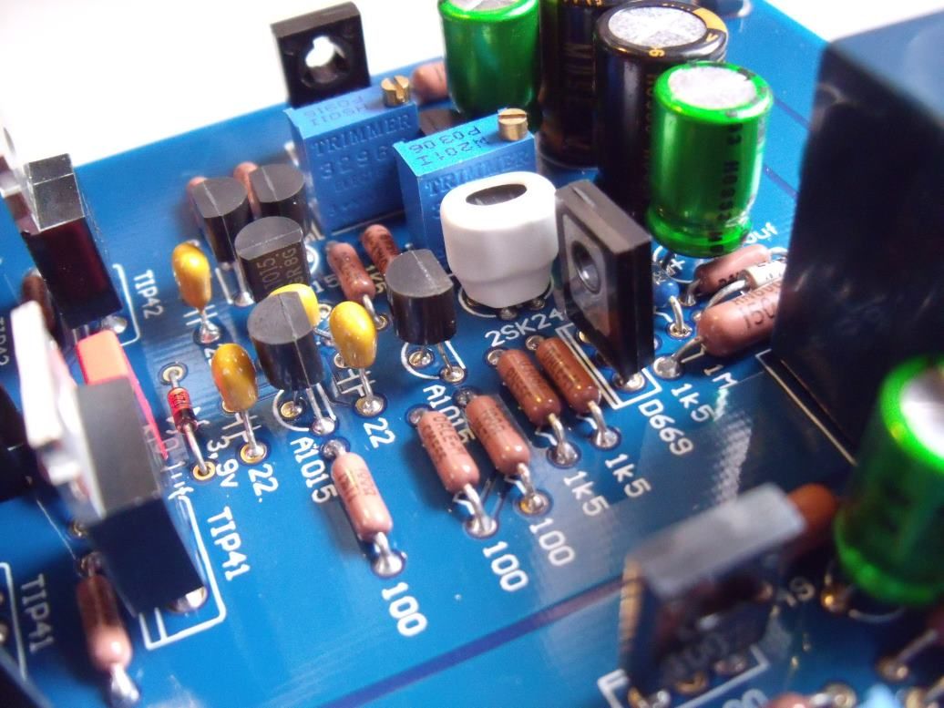 |
|
|
|
Post by PinkFloyd on Aug 26, 2010 20:39:41 GMT
The transformers should be here in the next few days.... I have gone with 18-0-18V (230V primary) and have asked my transformer manufacturer to make a good job of them (for audio usage)  I've gone for 160VA which should have more than enough headroom for this amp. I've scrubbed the "DIY enclosure" idea and instead have gone for one of these from the same guy who sells the Panda amp kit..... I've measured it all up and the Panda board + 160VA toroidal will fit comfortably. Added bonus that the enclosure comes with a fitted ON / OFF switch, LED and Headphone socket  It's also pre-drilled so a simple matter of fitting pot, RCA sockets, IEC, head socket etc. into position. You may say that £50 is "expensive" for an enclosure BUT, if you value your time and your time equates to "money", then £50 for a premade / pre drilled nice looking enclosure will be considered as money well spent  Where are we now? £40 for the amp kit, £50 for the enclosure..... call it £100..... STILL incredible value for money  |
|
|
|
Post by PinkFloyd on Aug 26, 2010 21:11:21 GMT
|
|
|
|
Post by PinkFloyd on Aug 26, 2010 21:15:45 GMT
I reckon this project will run @ about £150 max  |
|
mrarroyo
Been here a while!  Our man in Miami!
Posts: 1,003
|
Post by mrarroyo on Aug 26, 2010 23:22:33 GMT
That is one sharp looking unit there Mike. Enjoy it.
|
|
Deleted
Deleted Member
Posts: 0
|
Post by Deleted on Aug 26, 2010 23:46:34 GMT
Mike
I coimpletely agree. Unfortunately, the cost of decent metalwork is severely inflated by freight costs, especially to places like Australia.
Alex
|
|