Deleted
Deleted Member
Posts: 0
|
Post by Deleted on Jan 3, 2013 23:29:05 GMT
Shaun it'll be very nice to compare multilayer ceramic, preferably NP0 type, to HQ film but to make it apples to apples and pears to pears they'll both have to be the same value else you'll get different roll of points. Wouldn't you have by any chance some through hole NP0 2.2 or 4.7nF's in your parts box? I'm using very short interconnects (>20cm) so probably the buffer won't make much of a change in my system. My spoken French is not too shabby but my written is quite rusty for lack of practice though I guess it'll be good enough to order from their site. My only concern is shipping plus insurance cost being rather heavy parts. They accept credit card and money transfer no mention of PayPal I'm afraid. Merlin from DIYA has buyed from them a few times and says they are fine. Allan, isn't this forum basically about tempting one another???  Hi Javier i have some 4n7 poly caps somewhere  I'll dig two out and post them off to you. yup could sound the same as your ceramics but you will have a way of finding out for sure. the small trafo's are not so heavy so could be viable. no rush for me on that front. take care |
|
Deleted
Deleted Member
Posts: 0
|
Post by Deleted on Jan 5, 2013 16:29:10 GMT
Hi All i tried out the 45Mhz Vanguard TCXO with Will's PK and also Leo's 5102. so with Trident PSU the Vanguard and Tent XO i struggled to hear any real differences between the two SQ wise. the Vanguard seems like a great Value unit and works well enough with Will's PK to leave mine in. thanks for the heads up Alex.  money well spent still sounding superb  and another build completed over on DIYA www.diyaudio.com/forums/group-buys/216669-joachim-gerhard-filter-buffer-es9022-37.htmlnot that it matters so much but it's nice to know that someone else notices a difference with buffered OP.  take care |
|
Deleted
Deleted Member
Posts: 0
|
Post by Deleted on Jan 5, 2013 17:26:03 GMT
Some interesting oscilloscope captures showing the output of a DAC (TI PCM1794 in this case) with and without output filter: -" This is the output voltage of the PCM1794 without filter and with a first-order filter.
The cutoff frequency is 72Khz, its a litle bit low , but this is only for demostration" Unfiltered:  Filtered:  |
|
Deleted
Deleted Member
Posts: 0
|
Post by Deleted on Jan 6, 2013 0:31:49 GMT
Some interesting oscilloscope captures showing the output of a DAC (TI PCM1794 in this case) with and without output filter: -" This is the output voltage of the PCM1794 without filter and with a first-order filter.
The cutoff frequency is 72Khz, its a litle bit low , but this is only for demostration" Unfiltered: Filtered: Hi Javier interesting the second picture looks cleaner but out of phase with the first @ that frequency. incidentally the imaging and BASS performance is IMHO improved by the buffer and has been reported over on DIYA also. if only we could build just by calculator we'd have the perfect amp/DAC or whatever in one swoop. and every one of them sounding just the same but some people do just that (yes i know it sounds unbelievable :  nope for me it's calculation and ears that win out most of the time. interesting post though all the same take care |
|
Deleted
Deleted Member
Posts: 0
|
Post by Deleted on Jan 6, 2013 11:28:01 GMT
Shaun, my only intention was showing the difference between no analogue filter at the output of a DAC and a 1st order Resistor-Cap (RC) like the recommended in the ES9023, I wasn't implying anything else and certainly not down talking your buffer, sorry if it sounded like that. 1st Order filter: 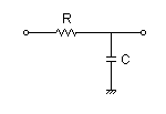 The reason for this is I had been running my PK filterless since the beginning because I thought the output PK caps were "optional" and having them in the signal path was a bad thing but then after reading that thread at DIYA, some one who knows a thing or two (  ) told me that those caps weren't optional at all and that they aren't actually in the audio signal path as their impedance in the audio band is too big to affect it in anyway and that they only diverting freqs above the calculated roll off point to GND with a 20dB/decade (6dB/octave) gradient. I didn't know ALL DACs need a LPF of whatever order and type to filter high freq garbage. Higher order filters would have sharper gradients and will be more agressive at getting rid of HF rubbish possibly being more effective at the task though I don't know if it could introduce any negative side effects or at which freqs they'll appear. |
|
Deleted
Deleted Member
Posts: 0
|
Post by Deleted on Jan 6, 2013 12:27:21 GMT
Shaun, my only intention was showing the difference between no analogue filter at the output of a DAC and a 1st order Resistor-Cap (RC) like the recommended in the ES9023, I wasn't implying anything else and certainly not down talking your buffer, sorry if it sounded like that. The reason for this is I had been running my PK filterless since the beginning because I thought the output PK caps were "optional" and having them in the signal path was a bad thing but then after reading that thread at DIYA, some one who knows a thing or two ( ) told me that those caps weren't optional at all and that they aren't actually in the audio signal path as their impedance in the audio band is too big to affect it in anyway and that they only diverting freqs above the calculated roll off point to GND with a 20dB/decade (6dB/octave) gradient. I didn't know ALL DACs need a LPF of whatever order and type to filter high freq garbage. Higher order filters would have sharper gradients and will be more agressive at getting rid of HF rubbish possibly being more effective at the task though I don't know if it could introduce any negative side effects or at which freqs they'll appear. Hi Javier don't worry i never read it that way 8-)and it's nice to have an open chat about such things without the drama.  I'm not sure that all DAC's would benefit but after building and listening to Leo's cheap DAC I'm starting to believe that the ones that use a charge pump might. i have another buffer on order so it will be interesting to find out. and your explanation of what those caps are doing is spot on. i do still think that the caps are optional depending on what sound people are looking for. some use them and others not which is fine. same with the OP buffer but IMHO those caps only address half of the problem. i use Will's PK driving 1M long cables and found the PK more than a little sensitive to cable capacitance. theoretically the 9023 should have no problem driving such cables but to my ears it does. I've not heard such large differences in SQ just from swapping cables before with any other piece of kit so it did make me think a little. I've found that without the buffer the 9023 with low capacitance cables generally sound better than high. some might say that it's not so but just speaking from what i hear in my set up. i hear no such restrictions cable wise with the buffer in place. so from what I've heard the filter cap does a nice job of taming the top end and the filter buffer improves things still further. the buffer makes the DAC much less sensitive to cable differences and improves the sound to my ears. I'll send you the caps so that you can try for yourself but i would recommend using Leo's turned socket arrangement so the caps can be plugged in and taken out more easily. I'll also send you some sockets so that you can experiment a little. take care |
|
leo
Been here a while!  Team wtf is it?
Posts: 3,638
|
Post by leo on Jan 6, 2013 19:33:29 GMT
Have to agree with you Shaun regarding capacitive loads with these dacs. Regarding those filter caps its certainly worth comparing with and without. The sockets help for quick testing, if you like the caps simply remove the sockets and solder the caps inplace . In my setup those caps made a difference, I liked it better without them, obviously every setup won't be the same |
|
Deleted
Deleted Member
Posts: 0
|
Post by Deleted on Jan 6, 2013 23:32:12 GMT
Have to agree with you Shaun regarding capacitive loads with these dacs. Regarding those filter caps its certainly worth comparing with and without. The sockets help for quick testing, if you like the caps simply remove the sockets and solder the caps inplace . In my setup those caps made a difference, I liked it better without them, obviously every setup won't be the same Hi Leo yup I've noticed larger SQ variations when changing cables than I'd have expected. the filter caps are worth trying and as you say easy to experiment with. take care |
|
pagan
Been here a while!
Posts: 512
|
Post by pagan on Jan 7, 2013 10:47:40 GMT
Shaun, my only intention was showing the difference between no analogue filter at the output of a DAC and a 1st order Resistor-Cap (RC) like the recommended in the ES9023, I wasn't implying anything else and certainly not down talking your buffer, sorry if it sounded like that. 1st Order filter: The reason for this is I had been running my PK filterless since the beginning because I thought the output PK caps were "optional" and having them in the signal path was a bad thing but then after reading that thread at DIYA, some one who knows a thing or two ( ) told me that those caps weren't optional at all and that they aren't actually in the audio signal path as their impedance in the audio band is too big to affect it in anyway and that they only diverting freqs above the calculated roll off point to GND with a 20dB/decade (6dB/octave) gradient. I didn't know ALL DACs need a LPF of whatever order and type to filter high freq garbage. Higher order filters would have sharper gradients and will be more agressive at getting rid of HF rubbish possibly being more effective at the task though I don't know if it could introduce any negative side effects or at which freqs they'll appear. Javier the pcm1794 is a current output dac, and the filter circuit is usually in the i/v circuit. the es9023 is a voltage output dac, it may/should have a range of filter settings programable in the dac, similar to the other voltage output dac's ie wolfson, akm439*, and others. Although, the outputs should always be tested with a scope, to see if the sinewave is clean and is within acceptable frequency range. Allan |
|
Deleted
Deleted Member
Posts: 0
|
Post by Deleted on Jan 7, 2013 12:50:10 GMT
Javier the pcm1794 is a current output dac, and the filter circuit is usually in the i/v circuit. the es9023 is a voltage output dac, it may/should have a range of filter settings programable in the dac, similar to the other voltage output dac's ie wolfson, akm439*, and others. Although, the outputs should always be tested with a scope, to see if the sinewave is clean and is within acceptable frequency range. Allan Hi Allan, I'm no expert but I think you are somewhat mistaking/mixing internal to the DAC chip digital filters with the external analogue low pass filers (LPF) we are discussing here. These LPFs are there to get rid of all digital noise residue that is not audio related and is a typical byproduct of Sigma Delta DACs. All DAC data sheets I've read show these LPF present. the ES9023 is no exception here as shown in its data sheet, though they can be of different order or complexity, independently of them being current or voltage output. Even the ES9018 can be made to work in voltage mode at a slight loss of performance but the LPF is still needed, the same goes for Wolfson's WM874x series which are voltage output too and the data sheet has a LPF as well (*). In the ES9023's case, the 1st order filter resistor is internal to the chip and only the cap is to be added. The difference between the PCM1794 or any other current out and the ES9023 is that the Sabre has an internal opamp based I/V but still all such chips like the PCM1793, DSD1793, PCM510x, ES2093, etc. need a LPF. The ES9023 doesn't have the "software mode" needed to change internal filters it only runs in "hardware mode". (*) BTW, interesting the comment on the WM8741's data sheet recommended implementation- page 62, fig. 82 2nd note: -" Capacitor dielectrics can cause distortion to the analog signal. Wolfson recommends that multilayer ceramic capacitors be used, with dielectric material C0G or Np0 for optimum performance"- |
|
Deleted
Deleted Member
Posts: 0
|
Post by Deleted on Jan 7, 2013 12:57:26 GMT
the second picture looks cleaner but out of phase with the first @ that frequency. I asked about this and got this answer: -" The garbage on the above picture just triggered on a HF signal crossing near the 0 line where the cleaner version triggered on the actual 1kHz sinewave. That happened to be at a point where the sinewave was going up.
So the filter does not rotate the phase nor can it in anyway as the filter is not active at 1kHz thus cannot cause phase shifts."- |
|
Deleted
Deleted Member
Posts: 0
|
Post by Deleted on Aug 1, 2013 22:17:24 GMT
Reviving an old question that didn't seem to get an answer;
I was looking at the board again today and the same question popped into my head and I then remembered it had been asked before.
Any thoughts?
|
|
Deleted
Deleted Member
Posts: 0
|
Post by Deleted on Aug 4, 2013 18:16:53 GMT
I have a list of questions in addition to the above;
1) Why is there a 4k7R from 3.6v to pin 15 when 100kR is specified by Sabre?
2) Why were the "gnats poos" caps values changed from the specified 1uf to 2.2uf on pins 5, 9 to 10, 11 to 12 and pin 6 which some did change to the spec'd 10uf.
3) would it make more sense to run a 1uf from pin 4 to 12?
If these things are worth changing to the spec's from Sabre I'll have a tinker.
Ta
|
|
Deleted
Deleted Member
Posts: 0
|
Post by Deleted on Aug 17, 2013 14:34:51 GMT
OK, I have gone ahead with the list of mods as dictated by the 9023 application diagram. Some worked out well and others did not; The 100KR from 3.6v to Pin15 proved to really mess things up, with or without a 2u2 to ground. No intermediary values were tried. Said 2u2 proved to be unstable on its own, it would play for about 30 mins then break up into static. Edit This was in ASYNC mode, my other board running in SYNC was quite happy with this mod. I do have to point out that I used through hole devices here as I had no SMD available, which may have some bearing. Placing 1uf SMDs (0603) across 9023 pins 9-10, 11-12 & 5 to ground were a definite improvement over the 1uf through hole caps they replaced. Added to that a 10uf oscon from 6 to Aground was also beneficial. The oscillator's cap was changed from a 10uf oscon to a 10nf X7R and again brought an improvement. Once all the successful mods were put together the only down side was an over brightness. To fend this off I upped the 2n2 caps in the filter to 4n7 which was almost miraculous! All improvements were kept and the HFs were beautifully calmed down. This is the best my PK has sounded by quite some margin so I'm very pleased that the effort was worthwhile.  |
|


 I'll dig two out and post them off to you.


 ) told me that those caps weren't optional at all and that they aren't actually in the audio signal path as their impedance in the audio band is too big to affect it in anyway and that they only diverting freqs above the calculated roll off point to GND with a 20dB/decade (6dB/octave) gradient. I didn't know ALL DACs need a LPF of whatever order and type to filter high freq garbage.


