|
|
Post by JohnnyBlue on Feb 8, 2010 7:51:01 GMT
I've just bought one of these and, despite requests to the seller for help, I've not got any response from him. I recognise most of the components, but am not sure what certain of the items are. If you look at this photo, there are some things about which I'm not clear (circled in red). I've deduced by their number that the 3 tiny rectangular items must be the 'green=jumpers' (see circuit diagram) but I'm not sure what they're for: why can't I just use a bit of wire to connect the points on the PCB. And what is the long plastic section, with many pins along it: I presume they are link pins or may be to stick through the PCB, but don't know how or why to use them. Do they fit into the little black connectors (the 'green=jumpers')? Why are there so many of them? Presumably I snap or snip them off to use them? Close-up of the jumpers and pins in question. And there are the wires in the resistor packet (above and to left of the red oval), without resistors on them: presumably they are also for linking? |
|
|
|
Post by JohnnyBlue on Feb 8, 2010 8:54:54 GMT
Apologies! I've now fixed the links in the above post: please let me know if they are not working properly for you!
|
|
Will
Been here a while!  Ribena abuser!
Member since 2008
Ribena abuser!
Member since 2008
Posts: 2,164
|
Post by Will on Feb 8, 2010 9:16:44 GMT
Hi johnnyblue,
The long plastic bit is used where the green (jumper) section goes. You snip two pins of the long piece and solder them in. I guess that the instructions tell you what adding/removing the jumpers does? When you build it and have it working, see what effect the jumper have, and when you are happy, you can solder links in where the jumpers are needed in place.
The wires are for linking out the areas noted in the blue section, by the looks of it.
|
|
|
|
Post by JohnnyBlue on Feb 8, 2010 9:23:10 GMT
Thanks, Will. There aren't any instructions apart from the circuit diagram! I'm just baffled as to why the seller goes to all the trouble (and the expense) to include those three jumpers and the strip of pins when it seems all they do is make an electrical connection, which can be done better by a soldered wire?
|
|
|
|
Post by PinkFloyd on Feb 8, 2010 20:06:29 GMT
You can also use those pins if you want to solder components on the "top" of the board.... let's assume you were experimenting with different values of resistor, instead of constantly having to remove the board you just solder onto the pins that would be sticking out of the board topside up. You don't need to use them to jumper, just use a wire link, but the pins may come in handy for other things.
Mike.
|
|
|
|
Post by JohnnyBlue on Feb 8, 2010 20:36:09 GMT
Thanks for the tip! I've now built the amp, and much to my surprise and joy, it works! The only slight glitch is that the LED doesn't light up, but I'm not going to lose sleep over that. Interestingly enough, I tried removing the jumpers, one by one, whilst listening, and guess what? Nothing happened! So, not only could I use a wire connection instead of the jumpers, but they're not apparently needed! This is getting mysteriouser and mysteriouser! I also noticed whilst doing the job that some of the wire connections I had to make were between parts of the PCB that were adjacent and could have been connected by copper tracking. I can only conclude that the PCB has other purposes, as the note on the circuit diagram suggests, with its references to 'reserved' sections for other projects. Now to find a suitable box to fit it all in... Thanks again to all who have replied here. |
|
|
|
Post by PinkFloyd on Feb 8, 2010 21:15:14 GMT
Thanks for the tip! I've now built the amp, and much to my surprise and joy, it works! The only slight glitch is that the LED doesn't light up, but I'm not going to lose sleep over that. Interestingly enough, I tried removing the jumpers, one by one, whilst listening, and guess what? Nothing happened! So, not only could I use a wire connection instead of the jumpers, but they're not apparently needed! This is getting mysteriouser and mysteriouser! I also noticed whilst doing the job that some of the wire connections I had to make were between parts of the PCB that were adjacent and could have been connected by copper tracking. I can only conclude that the PCB has other purposes, as the note on the circuit diagram suggests, with its references to 'reserved' sections for other projects. Now to find a suitable box to fit it all in... Thanks again to all who have replied here. Are you sure you've got the LED the right way round?.... long leg goes to cathode and short to anode.... try swapping it round  Mike. |
|
|
|
Post by JohnnyBlue on Feb 8, 2010 21:22:43 GMT
Are you sure you've got the LED the right way round?.... long leg goes to cathode and short to anode.... try swapping it round Mike. Aaargh! I didn't know that! And now I've snipped off the extra wire, so don't if it is that! I'll try swapping it round, but I'm even more amazed then that it works at all, I had no idea! |
|
Will
Been here a while!
Ribena abuser!
Member since 2008
Posts: 2,164
|
Post by Will on Feb 8, 2010 21:45:05 GMT
The cathode (-ve) of the led might have a slight flat on the rim of the led body, so that might help. It does sound like the led is backwards though, but it's no biggie.
|
|
|
|
Post by JohnnyBlue on Feb 8, 2010 21:54:40 GMT
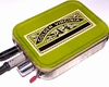
Good news! Have extended the LED wires (so it can reach the outside of whatever casing I choose to put it in, an old tin of Golden Virginia is looking favourite at the moment!) and swapped them round, so now have a lovely bright blue LED!
Many thanks, people!
|
|
Will
Been here a while!
Ribena abuser!
Member since 2008
Posts: 2,164
|
Post by Will on Feb 8, 2010 22:41:34 GMT
Good Stuff! It's pretty satisfying making something and it working well, isn't it?
Like the idea of the Golden Virginia tin as well, sounds suitably different to the penguin tins that get used.
|
|
|
|
Post by PinkFloyd on Feb 8, 2010 23:31:57 GMT
Good news! Have extended the LED wires (so it can reach the outside of whatever casing I choose to put it in, an old tin of Golden Virginia is looking favourite at the moment!) and swapped them round, so now have a lovely bright blue LED! Many thanks, people! Welcome to the club, sorry about your sanity  |
|
|
|
Post by JohnnyBlue on Feb 9, 2010 6:55:05 GMT
Thanks for the encouragement!
But...
Doh! Silly me! Flushed with success yesterday, I started to measure the dimensions of the completed amp to see if I could use a smaller enclosure (using a steel rule!).
I managed to short out the lovely blue LED, so it worked beautifully for about 2 hours! What a chump.
Any ideas what sort of spec it would be so I can replace it?
|
|
Will
Been here a while!
Ribena abuser!
Member since 2008
Posts: 2,164
|
Post by Will on Feb 9, 2010 9:47:58 GMT
What colour do you fancy? If you pop along to Maplin's you can get a standard 3mm led of your choice, so that you have the colour you want. www.maplin.co.uk/Family.aspx?Menu=1692&worldid=-2Ignore the 5V/12V offerings for now, and look for 3mm standard. If you want a physically bigger led then go for 5mm (it's the led diameter) If you want some thing a bit different, Mike (pinkfloyd) sells nice purple led. |
|
|
|
Post by JohnnyBlue on Feb 9, 2010 20:03:32 GMT
Phew! That's a relief: I thought a new LED might be expensive! (I'll see if I can get one to match the tin!) Anyway, it's not pretty, but it's mine, all MINE (well, apart from the CMOY kit!). Great fun, and a nice sense of achievement. Look out Naim, here I come! |
|
|
|
Post by PinkFloyd on Feb 9, 2010 23:12:00 GMT
Phew! That's a relief: I thought a new LED might be expensive! (I'll see if I can get one to match the tin!) Anyway, it's not pretty, but it's mine, all MINE (well, apart from the CMOY kit!). Great fun, and a nice sense of achievement. Look out Naim, here I come! Hey Johnny, that looks great (I'm a Golden Virginia smoker myself) have you got any under the hood shots? Mike. |
|
|
|
Post by PinkFloyd on Feb 9, 2010 23:12:53 GMT
|
|
|
|
Post by JohnnyBlue on Feb 10, 2010 7:47:10 GMT
I was hoping you wouldn't ask: the wiring is still at the Spaghetti Junction stage. Give me a bit of time to try and make it look a little less naff! (Just noticed that photo really shows up the warts-an'-all of the tin, it doesn't look that bad in real life!)
|
|
|
|
Post by PinkFloyd on Feb 10, 2010 10:45:17 GMT
I was hoping you wouldn't ask: the wiring is still at the Spaghetti Junction stage. Give me a bit of time to try and make it look a little less naff! (Just noticed that photo really shows up the warts-an'-all of the tin, it doesn't look that bad in real life!) It's called "patina" Johnny and I like it Much better than these sparkling "new" mint tins.... I can almost smell the nice fruity Golden Virginia tobacco just from looking at the tin.... lovely |
|
|
|
Post by PinkFloyd on Feb 10, 2010 10:49:36 GMT
You'd have a hard job making a GV amp these days.... 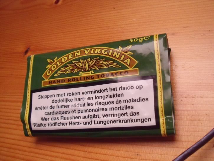 |
|
|
|
Post by JohnnyBlue on Feb 10, 2010 14:07:39 GMT
You'd have a hard job making a GV amp these days.... Thank God the health warning isn't in English! Anyway, here's the innards (zero style, but I'm so chuffed it works!): 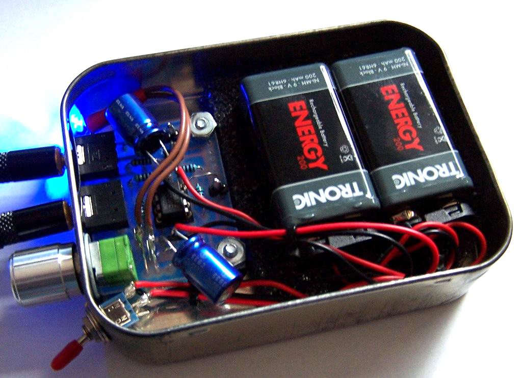 Incidentally, this was the first time of use of the cheapo-from-Lidl NiMH PP3 batteries, and they ran out last night after only a couple of hours. Is this design one that would use a lot of battery power, or is it that these particular NiMH batteries are just not very good (it was their first charge/discharge, too, so this should get better). Either way, I need to get another pair: these are cheap. Is it a false economy to get the cheap rechargeables? I'm reluctant to spend as much on a new set of batteries as I did on the CMOY kit! |
|
Will
Been here a while!
Ribena abuser!
Member since 2008
Posts: 2,164
|
Post by Will on Feb 10, 2010 14:56:45 GMT
I like your style with that tin, I must admit. Although my Dad isn't a smoker, my grandfather was, and he used to use GV in his pipe. My Dad had all the tins to store his electronic components in. Every time you went get a resistor or something, it was accompanied by this lovely smell of GV! Anyway, for all sorts of reasons, I like it. Seems you can get them off eBay for a couple of quid as well.....
As for your batteries, they are rated at 200mAh, which means it can supply 200mA for one hour, or 400mA for half hour or 100mA for two hours, you get the drift. The louder you play the music, the more current it will consume, and the opamp will also be a consideration in current draw. The battery will get better after a few cycles. You are getting a new led? Go for a low current version, it'll help battery life a little. If you are getting new batteries, then go for ones with a larger mAh rating (I think 270-290 from a couple of mini3 I've built in the past for people).
|
|
|
|
Post by JohnnyBlue on Feb 10, 2010 15:49:03 GMT
Yes, I'll get a new LED next time I can get to a Maplins.
BTW, the GV tin was my Dad's: like most people of his generation (born 1912), he smoked like a chimney, then used the tins for storing screws, nails, etc. (he was a joiner by trade).
|
|
Deleted
Deleted Member
Posts: 0
|
Post by Deleted on Feb 10, 2010 16:33:36 GMT
 Incidentally, this was the first time of use of the cheapo-from-Lidl NiMH PP3 batteries, and they ran out last night after only a couple of hours. Is this design one that would use a lot of battery power, or is it that these particular NiMH batteries are just not very good (it was their first charge/discharge, too, so this should get better). Either way, I need to get another pair: these are cheap. Is it a false economy to get the cheap rechargeables? I'm reluctant to spend as much on a new set of batteries as I did on the CMOY kit! I can't speak for the circuit but I think the 200mAh is a giveaway, that's towards the lower end of the power range for PP3s. Also those Lidl jobbies don't last as many charges as others, I guess you get what you pay for. These are at the other end of the scale, with a price to match. There is a thread here, somewhere, that discussed this very thing, damned if I can remember where  EDIT EDIT= Sorry Will, I answered without refreshing the screen first, I didn't see your post 'til after I posted. |
|
Will
Been here a while!
Ribena abuser!
Member since 2008
Posts: 2,164
|
Post by Will on Feb 10, 2010 16:55:52 GMT
No worries mate, your whopping 500mAh 9V has much more girth than my measly 270mAh  |
|