Will
Been here a while!  Ribena abuser!
Member since 2008
Ribena abuser!
Member since 2008
Posts: 2,164
|
Post by Will on Aug 7, 2008 18:14:49 GMT
Am I reading the cct diagram right? Dave, hope you dont mind, but I'm posting from your JLH pdf version 1.41 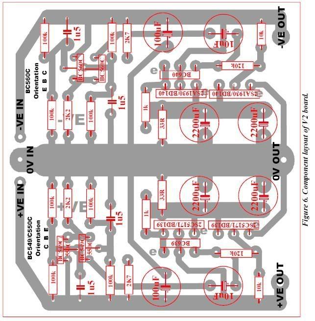 the 10uF (bottom right) is the same orientation as on the board. Mind you I'm tired, mildly stressed and need a cider! ... thats my excuse... |
|
leo
Been here a while!
Team wtf is it?
Posts: 3,638
|
Post by leo on Aug 7, 2008 19:25:39 GMT
the cap on that drawing is wrong, it needs altering , if you look at the schematic in the original JLH article the 2k7 going to that 10uf and collector of the second BC549 pair comes from the supply rail, in that drawing you'll have about 3 and a half volts less than full +v supply going to the caps -v leg I'd advise anybody who's copied this drawing to change that cap  |
|
Will
Been here a while!
Ribena abuser!
Member since 2008
Posts: 2,164
|
Post by Will on Aug 7, 2008 20:05:00 GMT
Leo, thanks for clarifying that.
Canjunkie, you have PM!
|
|
Deleted
Deleted Member
Posts: 0
|
Post by Deleted on Aug 7, 2008 21:35:10 GMT
A good rule of thumb with semiconductor circuits, is that when using a -VE supply rail, the coupling capacitor has it's -VE side connected to the collector of the transistor, and the +VE side connected to the next stage, or the output.When using a +VE supply, the +VE side of the coupling capacitor is connected to the collector, and the -VE side connected to the next stage, or output.
Alex
|
|
|
|
Post by canjunkie on Aug 7, 2008 21:55:51 GMT
|
|
leo
Been here a while!
Team wtf is it?
Posts: 3,638
|
Post by leo on Aug 7, 2008 22:23:32 GMT
No need to be  mate, we all make small errors at some stage no biggy The pcbs are nice and don't require any mods etc, its just a simple cap re orientation |
|
Deleted
Deleted Member
Posts: 0
|
Post by Deleted on Aug 7, 2008 22:42:06 GMT
Dave
Like I said in the bit about rule of thumb, people like us do things like inserting components,
almost on auto pilot because we are aware of that. When it comes to properly documenting what we have done, that's a different matter ! Many times I have revisited something years later, that I didn't document properly.Perhaps only scribbled on a bit of paper for the actual job, and wasted hours trying to work out what I did originally ! A case in point was a video switcher that I had built years ago. Took me hours to work out recently, WTF I had done with the relays. As they said in a cartoon I saw stuck on the wall of a toilet "The job's not finished until the paperwork's done."
Alex
|
|
Deleted
Deleted Member
Posts: 0
|
Post by Deleted on Aug 8, 2008 6:16:39 GMT
The penny just dropped (for me) !! When did the negative regulator change to the top of the PCB? (with inputs on left, outputs on the right). No wonder I'm getting so confused. Although this will work fine, doing it this way conflicts with original JLH article which I read every night before going to bed.  I think the original PCB image must have been rotated, mirrored and flipped one to many times.  If the PCB gets an update one day, the 10uF cap can be rotated 90 degrees so all caps on the board have exactly the same orientation. regards |
|
Will
Been here a while!
Ribena abuser!
Member since 2008
Posts: 2,164
|
Post by Will on Aug 8, 2008 6:23:34 GMT
Like I said in the bit about rule of thumb, people like us do things like inserting components, almost on auto pilot because we are aware of that. The force must be strong in you lot, and quite wobbly in me! All my electronics training was geared towards repair, so 'feeling' the circuit is another skill to learn. Nice ROT though, thanks. |
|
|
|
Post by canjunkie on Aug 8, 2008 7:08:50 GMT
When did the negative regulator change to the top of the PCB? (with inputs on left, outputs on the right). No wonder I'm getting so confused. Although this will work fine, doing it this way conflicts with original JLH article which I read every night before going to bed. I think the original PCB image must have been rotated, mirrored and flipped one to many times. If the PCB gets an update one day, the 10uF cap can be rotated 90 degrees so all caps on the board have exactly the same orientation. regards Its not just me that takes tech articles to bed then The board was tweaked to have the -ve side 'on top' to match the orientation of the Silicon Chip Headphone Amp & PSU kit. The problem with the cap the wrong way round was down to a cut and paste error in the graphics programme I did the component guide with. Its is highly likely that the thing thats been flipped, mirrored & rotated a few times too many is me  If anyone has any suggestions for improving the layout I'm all ears. Like Wilbur, I'm from a service background so all this design & modification is new territory - great fun though |
|


