jonclancy
Been here a while!  Mr. Ripple Eater
Amateur EAGLEist
Mr. Ripple Eater
Amateur EAGLEist
Posts: 1,131
|
Post by jonclancy on Jun 16, 2008 15:41:22 GMT
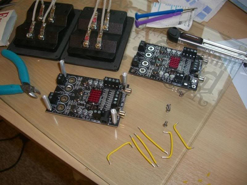
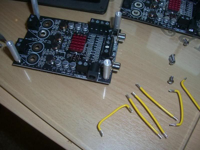
Continuing on the Elcheapo theme, I've piggybacked the TA2024 amps and tried them in the system. With the variable (op amp) output from the CDP, they were horrid. Overblown bass and no definition. However, using a better active pre really helped!!! They are brilliant for the money, sound better than OK without modding, and run fine on a 12V SLA battery. I'm thinking about increasing the output cap values. Here are some pics...... 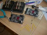  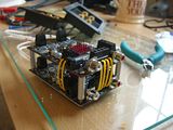 Cheers Jon |
|
|
|
Post by regal on Jun 20, 2008 15:30:52 GMT
Found this thread after reading the Lampnators reviews of the DAC. The Lampinator is absolutely the wrong circuit to use for this DAC. Be it discrete SS or tube you need a stage that does a balanced to unbalanced transfer. Otherwise you won't get the common mode noise rejection and not come close the the CS THD specs. Also the Lampinator (SRPP) has way to much gain. Broskie's Cathode follower is what should be used if you want tubes. www.tubecad.com/2006/08/blog0075.htmAlso my understanding is that S-D DAC's like this do NOT have any internal opamp. Leo, that is a very useful stage what are you using for Q1,Q2,Q6 ? |
|
leo
Been here a while!
Team wtf is it?
Posts: 3,638
|
Post by leo on Jun 20, 2008 20:40:29 GMT
Q1 and Q6 inputs are 2SD786, the Emitter follower is a BC517 Darlington, I basically used what I had.
I also tried J-fets for the input and output, also mixed them but didn't like the results
|
|
leo
Been here a while!
Team wtf is it?
Posts: 3,638
|
Post by leo on Jun 20, 2008 20:47:45 GMT
Talking of Lampizator tube stage, cover your eyes SandyK  I've tried op-amps, discrete (I'll post a pic of the discrete soon) it made sense to give the old valve stage a try too, here it is in all its WTF rats nest glory ;D Totally quick lash up can't you tell!  |
|
jonclancy
Been here a while!
Mr. Ripple Eater
Amateur EAGLEist
Posts: 1,131
|
Post by jonclancy on Jun 20, 2008 22:14:01 GMT
WTF? Stunning lash up there!!
How does it sound?
|
|
|
|
Post by canjunkie on Jun 20, 2008 23:12:34 GMT
Compared to the PA system I opened up this afternoon that looks quite tidy  Be careful Leo, the SandyK is not a well man at the minute - I'm not sure he'll take the shock of dangling tubes too well |
|
Deleted
Deleted Member
Posts: 0
|
Post by Deleted on Jun 20, 2008 23:26:18 GMT
Dave Doesn't worry me, because I know if those frigging relics from halfway through last century were any good in that application (or for ANY application, for that matter !  that Leo would have tidied up the rat's nest ! Alex |
|
pagan
<100
How do I activate my account?
Posts: 81
|
Post by pagan on Jun 21, 2008 0:58:34 GMT
Q1 and Q6 inputs are 2SD786, the Emitter follower is a BC517 Darlington, I basically used what I had. I also tried J-fets for the input and output, also mixed them but didn't like the results I've used 2sk389 on inputs, because too lazy to match 2sk170 fets. And bc517 outputs. Also early one was matched bc550c's on input, bc517 outputs. Leo, how about a LM394 for the inputs? I have some MAT02's sitting around, I may try them, hfe not as good as 550C's but don't need to match them. Even the 2SC1815BL's should work, Or SSM2210? |
|
Deleted
Deleted Member
Posts: 0
|
Post by Deleted on Jun 21, 2008 1:07:21 GMT
Allan
I have a couple of spare high HFE LM394.
Alex
|
|
pagan
<100
How do I activate my account?
Posts: 81
|
Post by pagan on Jun 21, 2008 1:41:19 GMT
Allan I have a couple of spare high HFE LM394. Alex Alex I will have to try them. The LM394's I have, HFE wasn't good. I get better when matching 550C's I've been meaning to try this buffer on the wolfson dac. |
|
Deleted
Deleted Member
Posts: 0
|
Post by Deleted on Jun 21, 2008 2:08:37 GMT
Allan
I have 4 or 5 recycled ones with HFE between 750-900, OR a couple of unused, with HFE of approx. 1,650. Your pick.
Alex
|
|
|
|
Post by jeffc on Jul 6, 2008 22:30:31 GMT
On the weekend I inserted JLH PSRR boards (thanks Canjunkie/sandyk for working through assembly hiccups with these), supplying both the opamp and digital sections of the DAC, very worthwhile improvement.
And Leo, with these now inserted, IYO is there any point to retaining the largish caps supplying the digital section on-board regulator (470uF Silmic) and the LM4562 opamp (47uF tantalums). You have mentioned previously favoring smaller values, although I'm not knowledgeable enough to know why.
cheers.. Jeff
|
|
Deleted
Deleted Member
Posts: 0
|
Post by Deleted on Jul 6, 2008 22:39:15 GMT
Jeffc
I find that the "house sound" of different types of bypass capacitors is usually negated by the much lower impedance of the JLH supplying the power, if it is close by. I would still try replacing the 47uF tantalum withy a normal electro, but I would be surprised if there is much (if any) audible difference.
Alex
|
|
|
|
Post by jeffc on Jul 6, 2008 23:27:58 GMT
Alex,
You have mentioned before that the JLH's super low impedance tends to neutralize any 'flavor' added by boutique caps. Thats good, the DAC certainly sounds very neutral and I can move on to fixing the DC offset problem.
I have a 4.8V 4xsubC NiHM model racing car battery pack in use with a Trends UD10 DAC/USB-SPDIF converter with headphone out running direct from its DAC chip. The battery pack has an output impedance <15 mohm and apparently when used to run model car engines, can pull 30A in an instant. SQ using it is chalk and cheese compared to USB power.
cheers.. jeffc
|
|
leo
Been here a while!
Team wtf is it?
Posts: 3,638
|
Post by leo on Jul 7, 2008 10:58:49 GMT
The output stage in the Elcheapo looks to be a Butterworth but theres a few values that don't make sense and explains the offset If you want to greatly reduce the DC offset to very low mV resistor values R8/14 Right channel R9/17 and cap values C32/34 right channel C33/35 left channel need matching. For some reason they use 36k + 56pf on the inverted side and 22k+1N on the non inverted side  Ray (6h5c) suggested trying changing R8/14/9/17 to 30k and C32/34/33/35 to 150pf. This reduces DC offset to +/-1mV and also makes the output flatter. Coupling caps can be bypassed For the decoupling caps I currently use 2.2uf tants bypassed with 10nf NPO/COG for the op-amp, I know tants are not regarded much normally but because I use AD826 it helps with stability , I actually find any electrolytic adds more colouration than tants, if using tants I try to keep their values lower than 10uf if possible, higher values in these tend to be worse. Depending on the type of regulation and application if the value needed is 10uf or less I use tants. Non of my kit sounds bright either |
|
jonclancy
Been here a while!
Mr. Ripple Eater
Amateur EAGLEist
Posts: 1,131
|
Post by jonclancy on Jul 21, 2008 15:39:53 GMT
I was just looking at the 4397 Datasheet and saw that the VA draw was nominally only 20mA. Assuming VD is the same, then a pair of Fleas (one with the dual diode mod for 3V3) could do the job. The 8416 only requires under 5mA for its 3V3 supplies. Hi, Here's a quick update: I've been at the Fleas and removed the XOs and installed a couple of diodes in place of the LEDs as described on the excellent Acoustica website. www.acoustica.org.uk/t/naim/35clockreg.htmlThe relevant extract: The two resistors at the opamp output are the feedback divider and set the opamp gain, and hence the output voltage. Here, the ratio is [(1300/820)+1] = 2.58x . With a 1.94v reference we get 5.0v output; using two forward-biased diodes (0.65v x 2) instead of the LED would give about 3.4v output, ideal for 3.3v systems in SACD players. Alternatively, keeping the LED and using a 1Kohm, multi-turn potentiometer to vary the feedback would be a good alternative if adjustability is required. I got 3V6 and 3V84 DC out of my Fleas, so it was out with the calculator and after a bit of resistor measuring, I worked out that I needed 1K Ohm on one Flea and 1K15 on the other to make 3V3 in theory. The one Flea is for VDigital, the other for the CS8416 power. I have a 3rd, unmodded, Flea that will be used for VAnalogue at 5VDC. However, I did notice that there is a MCLK input in the 4397 datasheet and possible to run at 11.2896 MHz (which I have here), so I might just use the 3rd Flea with XO for that and also a small feed for the 5V reference voltage. In which case, an ALW Super Reg at 5V can look after the Analog side of things. Finally, either the discrete stage or a couple more superregs at +- 15V for the opamp, and I think we might se some improvement. From there, it's OsCon time, but for now it'll be great so see what sorted power supplies do for this impressive little DAC. More news when it makes music......... Cheers Jon |
|
|
|
Post by tripmaster on Sept 9, 2008 13:47:10 GMT
I tested the dac before fitting parts and it worked fine.
The story so far...
Stage 1
Changed LM4562 OPAMP Sound: ok
---------
Stage 2
Removed and bypassed ps caps (C30, C31, C28, C27 & C54, C6) with thin wire. connected coupling caps and R68 resistors on RCA output, soldered two blobs to bypass chip on the base of board.
Sound: Treble is OK but bass really muffled and distorted - Sounds really bad.
----------
Stage 3
Change all other caps. Sound: Still sounds the same, but it still works!
I have not removed any of the smd caps, just bypassed with vishay
I have not changed any resistors.
Do you have any clues?
|
|
leo
Been here a while!
Team wtf is it?
Posts: 3,638
|
Post by leo on Sept 9, 2008 18:53:04 GMT
If your the same guy who's filled the board with Oscons /big film caps then theres one of the problems |
|
|
|
Post by tripmaster on Sept 9, 2008 20:47:24 GMT
Thats me!
|
|
|
|
Post by tripmaster on Sept 11, 2008 12:59:03 GMT
Hi
Late on Tuesday night...
Whilst listening to the DAC last night one of the temporary solder connections attaching the right channel lead to the coupling cap broke away.
I re-soldered the lead and at the same time decided to remove the two blobs of solder from the chip on the base of the board. I fired it up again and only the left channel works. All of the connections seem fine and both channels from my amp operate ok via a DAC MAGIC2 box.
I re-soldered the two blobs next to the chip and now the output is very quiet and extremely distorted.
This is not a good way to finish the evening!
Wednesday
Well...I have removed quite a number of the components previously added but am no further forward with regards to sound, still very distorted.
When I desoldered the small blobs from the base of the board next to the chip I think I may have damaged the solder pads (Solder is not sticking any more and they are barely visible).
Do you think I may have damaged this chip due to excessive heat? Or do you think the board is a right off?
Thanks in advance
Richard
|
|
|
|
Post by canjunkie on Sept 11, 2008 19:38:57 GMT
Any chance of posting some pics? It will help a lot.
|
|
leo
Been here a while!
Team wtf is it?
Posts: 3,638
|
Post by leo on Sept 11, 2008 20:06:43 GMT
Excessive heat can cause damage but its hard to say whats causing the problem tbh
Get the magnifying glass out and check for the obvious first like any small solder bridges across track or chip pins, any damaged track , some of the pcb print is very fine and can easily be damaged, also you may have to map the various track lines and measure each one, it may prove to be tedious I'm afraid
Check the 5v to dac , is it ok? is it low? also check the 3.3v for the digital, is this ok? also check the analogue +/-12v supply, make sure its going to the op-amp (pins 4 and 8)
|
|
|
|
Post by tripmaster on Sept 11, 2008 20:47:32 GMT
I am not sure how to attach photos on this site I have posted them on this forum theartofsound.net/forum/showthread.php?p=17978#post17978I have been playing around with some of the recommend cap values (I know the caps are a bit large) I have tested the output from the psu and I am getting 12v & 5v How do I check when connected to the board? |
|
|
|
Post by tripmaster on Sept 11, 2008 22:14:07 GMT
Hi I have checked all of he solder joints and I cant see bridging. I also checked the Digital voltage from the CS8416 and I am getting a reading of 3.33v on pin 23 and 21. I also have a reading of 13.24v from pins 4 and 8 on the opamp. I have not yet checked all of the tracks for continuity. After some considering my options I decided to remove the chip from the base of the board. Can anyone advise which pads I need to short for bypass? theartofsound.net/forum/showthread.php?p=17984#post17984 |
|
|
|
Post by tripmaster on Sept 12, 2008 9:06:22 GMT
Does anyone know the value of C7?
|
|


 that Leo would have tidied up the rat's nest !
