|
|
Post by harleymileage on Dec 18, 2006 4:57:54 GMT
Mike and Rick, Man you guys really know this stuff! I have been debating tackling that dip-socket. I do have a fair amount of experience soldering. But very little experience desoldering. I was thinking about buying some of that braid and/or a desoldering pump to experiment with before attempting it on my Heed.
Hey, where do you buy the opamps?
|
|
darynalexander
100+
will probably give you some sort of disease.
Posts: 179
|
Post by darynalexander on Dec 18, 2006 9:10:03 GMT
I heard that pump could suck up the pad, so soldering braid could be better? This could be crap, I'm not sure. aaaand now I'm scared of ruining the pads now. There are a lot of little improvements to be made to it, but primarily the bypassing and sockets make me nervous. Mike, would it be at all possible for you to mod another one? For as much as the startup cost of soldering supplies are, I could pay for postage to ship the amp and parts there and back, included with plenty of beer money for the trouble.  Alternately, I'll stick to the easy stuff, though everything else seems very tempting when described (especially the opamp stuff). Unless there's a special way for a brand n00b such as myself to successfully desolder the fragile opamp, bypass, and do under-the-board work? |
|
|
|
Post by PinkFloyd on Dec 18, 2006 11:47:08 GMT
From Vacuum tube Valley (yup,the folks who produce the magazine  ) "Capacitor Installation Tips: Remember to connect the inner foil side facing the output. In coupling caps, this means connecting the inner foil to the grid of the output tube and the outer foil to the plate of the driver tube. On some caps, the color of the wire indicates the inner foil side, on some the inner foil is marked and on others it is typically the right side of the cap when reading the value. On older caps, the outer foil is indicated by a band around the cap."www.vacuumtube.com/capacito.htmand no,I will NEVER pay close to a C-Note for a single 1uF cpacitor.Just aint gonna happen ;D I'll just have to assume it's on the right side then, the caps I mainly use don't make this clear www.evoxrifa.com/cap_catalog/pulsecap/phe426.pdf (not that I can see anyway) I always dress the buggers the same way round anyway and if replacing one cap with printing to the front will always install replacement cap with same orientation. Surprising how many amps have them all over the shop though Rick, usually bent over on the board and all higgeldy piggeldy into the bargain  |
|
rickcr42
Fully Modded
Rest in peace my good friend.
Posts: 4,514
|
Post by rickcr42 on Dec 18, 2006 14:34:38 GMT
one of those "Weird Science Tales" that seem totally off the wall,just another snake oil/voodoo audiophile nut job idea until you dig a bit deeper which surprisingly and by sheer coincidence came up at another forum I try to check in at every couple to three days,almost as if it was meant to be,that it was time to bring it up and being karma no way around it so did my duty ;D www.prodigy-pro.com/forum/viewtopic.php?t=12106&highlight=capacitor+outer+filmwww.prodigy-pro.com/forum/viewtopic.php?t=19871www.aikenamps.com/OutsideFoil.htmNot exactly sure when I came across this information for the first time but I can tell you I was curious about the little "stripe" at one end of film caps way back in the early seventies.It was always there yet to me for no apparent reason I could fathom not being mentioned in the cap code sheets and to me a SERIOUS OVERSIGHT ! If the manufacturer went out of his/her way to put the damn stripe ON don't you folks think SOMEONE should have had the decency to tell us WHY ? anyway,not trying to derail your thread Mike but trying to toss out some of the little things that again may make very little actual sonic difference alone but in the total accumulation of DO plus being either 100% FREE or at worst CHEAP as in using non-inductive resistors,are at the minimumn worth trying on the "can't hurt,may help" side of modding audio unlike the "think I'll try a $100 capacitor 'cause it IS a pretty bugger and I heard somewhere it sounds good" school of audio modification thought where you take a $50 amp then put $500 worth of aftermarket parts in to get a $10 increase in SQ. Not a stretch man since many just mod blindly after reading a page or two from a mod site not realising the ones that are valid are product specific designs and not "generic upgrade path" types and why you see even at the commercial level so many audio electronics having the EXACT same basic parts inside even though the absolute worst possible sonic choice many times but that is part of the times man where you need to use certain catch phrases or have a particual color scheme in mind under the hood that usually goes brown/red/green or you are not part of the "in the know" crew.color goes like this : Brown Vishay Resistor/Bright Red WIMA Caps/Pretty Green G-10 Fiberglass PCB. almost a damn Christmas Tree color scheme ! Use a different color cap ? Well now ALL the resistors need to be changed because the brown vishays no longer look right and I am not making this shit up ! Going for a "look" so the person can show off the inside amp porn has more importance than choosing the best part for that position in the circuit on the SQ vs. Cost merits alone which should be the primary goal here and one lucky for those of you who follow mikes advice he does NOT follow-he listens to the gear THEN decides (though he does need me to twist his arm on occasion to get him to try something new  ) EDITED For Additional Content :www.audience-av.com/auricap_application_notes.htm** |
|
rickcr42
Fully Modded
Rest in peace my good friend.
Posts: 4,514
|
Post by rickcr42 on Dec 18, 2006 15:17:10 GMT
...OK,maybe not totally "out" yet,Unfinished Business can't be left dangling in the breeze De-soldering is as much an art requiring practice as soldering with the real possibility of doing pcb damage a lot greater since the copper pads have already once been exposed to heat and heat is the copper pad killer.I'm not sure where this extra heat requiring RoHs crap will lead (trash heap/non-repairable /mod-able goods I think...) but the regular leaded parts and solder de-soldering technique has many versions. First I am the worlds worst with desoldering braid so even though I always have some it gathers dust.Others have nothing but good things to say about it so it is not the method but the person with me in this case being inept at it for whatever reason. My way is to use a "solder sucker" but NOT one of those fancy spring loaded solder pumps you see recommended in damn near every desoldering instruction page but the lowest tech cheapest SOB bulb types,the way I have been doing it since I screwed up my first SWTPC Plastic Tiger amp kit some thirty++ years ago when i put most of the part in backwards ;D The spring loaded pumps are a tad overpowering to me being an all or nothing thing.Pull back on the tension spring,lock the plunger,heat the joint,pull the release triger SUUUUUCK !!!!and if you don't get all the solder wind it up and do it agaion until you do. The solder "bulb" is a lot more gentle and under more human control so you squeeze the bulb to create the initial vacuum,heat the joint,place the nozzle over the area you want to remove the solder then simply release the bulb tension.a nice gentle but effective fwoooshif you don't get all the solder ? No biggy.Just squeeze the bitch and re-do the "Hi-Tech" version :  The "Lo-Tech" solder sucker (mine's about 20 years old  )  Armed with that and a piece of stiff wire to keep the tip clean (clothes hanger section  ) I am ready to rock ! I also go to the heavy artillery when I must with that being one of those DIP IC "desoldering" soldering iron tips along with a spring loaded IC remover because NO HUMAN I KNOW can heat 28 pins at the same time without the proper tool and unless you do not want to salvage the chip (at which time you just nip all the leads and remove them one at a time) the only way to avoid both part and solder pad damage or in my case winging the whole fkn thing into the nearest wall |
|
darynalexander
100+
will probably give you some sort of disease.
Posts: 179
|
Post by darynalexander on Dec 19, 2006 0:45:02 GMT
Thanks a lot, Rick, for all the information. If a pump or a sucker is easier to work than braid, I'll try that. Would you say the primary cause for concern when it comes to damaging pads is leaving the iron on it too long while sucking up the solder?
Mike, if it's an under the board mount, am I correct to solder it into position from the top of the board? How does one solder parallel resistors?
Thanks again, all. This thread is very useful not just for the Canamp but for soldering in general.
|
|
rickcr42
Fully Modded
Rest in peace my good friend.
Posts: 4,514
|
Post by rickcr42 on Dec 19, 2006 0:57:43 GMT
absolutely and that usually from being "undergunned" as in not enough heat.the trick is to melt the joint rapidly and get the iron off the pad ASAP and not have it settle in one spot while you wait for the solder to flow-pretty much the exact reverse of soldering 1-hot iron 2-keep it tinned 3-keep it clean by constantly wiping it on a damp sponge 4-give the iron enough time between "joints" to heat back up to full temp 5-NEVER try and solder heavy metal with the same iron you use on delicate parts or more often than not you end up havng to hold the iron there WAY too long and when that happens you invariably melt the plastic parts in the metaql assembly (like the insulators in jacks ) |
|
darynalexander
100+
will probably give you some sort of disease.
Posts: 179
|
Post by darynalexander on Dec 19, 2006 1:34:19 GMT
ah I think I see now. The joints are smaller, so leaving the iron on even a little too long could be a very bad thing. I'll be desoldering the capacitors first, before tackling the dip8. What wattage should I run on for these? The gun runs 15-40w. I'm still itching to know what will be in this Heed "Special Edition" version that I think was announed too early. I can't imagine it being as much of an upgrade as this, especially with the opamp rolling. I looked at the Silmic II's and can't find the 35v, so it will indeed be 25 for me. Any difference sonically? The data sheet showed them to be the same size, leads and all. And with that, I finally see that this thread has turned headphone listening from a journey to a hobby. |
|
rickcr42
Fully Modded
Rest in peace my good friend.
Posts: 4,514
|
Post by rickcr42 on Dec 19, 2006 2:16:54 GMT
I actually run three soldering tools unlike "normal folks" who use a single variable temp iron
1-30 watt grounded tip iron with a chisel tip for semicondictors
2-40 watt two wire iron with chisel tip for passives (resistors and caps)
3-100 watt gun for jacks and heavy metal
I also adjust solder diameter to the job so for small connections a small diameter solder and for large fat solder.
the old "you can bang a nail in with a rock but in the end it is better to use a proper hammer " thing where I like a specific tool for a specific job instead of a single universal tool for everything
|
|
|
|
Post by PinkFloyd on Dec 19, 2006 2:21:37 GMT
NO HUMAN I KNOW can heat 28 pins at the same time Piece of cake once you get used to it Rick. Large (hot) bit and a swipe accompanied by a pull on the chip (in unison with the hot swipe) and she'll come out in a wunner (in one go) it's all about confidence combined with technique here...... think "melting 28 pads in one go" and think "leverage" at the same time, piece of cake...... honestly. |
|
rickcr42
Fully Modded
Rest in peace my good friend.
Posts: 4,514
|
Post by rickcr42 on Dec 19, 2006 2:28:39 GMT
well my techique sucks which means my confidence is shot all to hell |
|
rickcr42
Fully Modded
Rest in peace my good friend.
Posts: 4,514
|
Post by rickcr42 on Dec 19, 2006 2:40:37 GMT
...so why i use one of these puppies for the heavy lifting  a bit tricky to get used to but a real aid once you do. BTW-been using OK Industries products since the 70s and can safely say I highly recommend anything made by this company |
|
|
|
Post by PinkFloyd on Dec 20, 2006 0:29:03 GMT
Mike, would it be at all possible for you to mod another one? For as much as the startup cost of soldering supplies are, I could pay for postage to ship the amp and parts there and back, included with plenty of beer money for the trouble. There has been a lot of interest and I can't refuse all you guys so, yes, I'll mod your amps. More on this after the Christmas holiday. Mike. |
|
Cuppa
<100
Sent me a GRADO got me banned
Boner fide member of the Canadian Goat deprecation society
Posts: 33
|
Post by Cuppa on Dec 20, 2006 21:08:19 GMT
Mike, would it be at all possible for you to mod another one? For as much as the startup cost of soldering supplies are, I could pay for postage to ship the amp and parts there and back, included with plenty of beer money for the trouble. There has been a lot of interest and I can't refuse all you guys so, yes, I'll mod your amps. More on this after the Christmas holiday. Mike. Looks like it's gonna be a very Happy New Year for us Heed owners! Mike, count me in. |
|
darynalexander
100+
will probably give you some sort of disease.
Posts: 179
|
Post by darynalexander on Dec 20, 2006 23:37:49 GMT
Now I'm excited instead of just scared stupid. I felt like I was going to perform open heart surgery on an infant.
Also, Mike, did you want me to pick up some spare Panasonics? You mentioned in the board previous that you can't get them in the UK. Heck, for that matter, anything you need from Digikey? Milk? Bread?
|
|
darynalexander
100+
will probably give you some sort of disease.
Posts: 179
|
Post by darynalexander on Dec 24, 2006 7:48:37 GMT
Is this the right dip socket? digikey.com part number: ED90032-ND
Also, how many of the 63v caps and 47/63 caps are there to replace?
Also, what are those behind the uf4007's, and can they be #&@*ed with? I'm piling on the shopping carts (btw, Pinkfloyd, do you want some panasonics?) as it is so I say why not.
Happy Christmahuanakwanzika, all.
|
|
|
|
Post by PinkFloyd on Dec 24, 2006 14:56:18 GMT
Is this the right dip socket? digikey.com part number: ED90032-ND Spot on! That's the turned pin Gold plated one. A couple of 470nF and a couple of 100nF. 10n 63V connected to diodes IIRC, you can leave them in position. Thanks for the offer of the Panasonics but I'm fine with the Dubilier caps, very good of you though  Same to you, have a good one |
|
darynalexander
100+
will probably give you some sort of disease.
Posts: 179
|
Post by darynalexander on Dec 26, 2006 7:25:46 GMT
found an alternative source on those 0.0047 polypropylenes. www.rapidonline.com part number 10-1450. They're more US friendly it would appear. Was also going to pick up those Riedon 12w 100ohms Rick mentioned earlier. |
|
darynalexander
100+
will probably give you some sort of disease.
Posts: 179
|
Post by darynalexander on Dec 28, 2006 5:15:15 GMT
Now I've gone and done it. The Radioshack by my house sold all this stuff, so I got a good iron, sodder, pump, braid, you name it. The iron is 40 watts, and since I am careful to begin with I figure my mistake if anything will be not touching it to the board long enough rather than too much. Besides, pride in work is important. if anyone can answer though, this is my only real soddering question at this point: how to mount on the underside of a board. With the film caps, do I just put the leads through the holes then clip like I normally would? With bypassing, do I solder the one component as usual, then go back and add more solder while heating the bottom polypropylene's leads to the solder? It's simply procedure at this point that gets me. If anyone could help, that's all I need! |
|
rickcr42
Fully Modded
Rest in peace my good friend.
Posts: 4,514
|
Post by rickcr42 on Dec 28, 2006 17:51:01 GMT
Now I've gone and done it. The Radioshack by my house sold all this stuff, so I got a good iron, sodder, pump, braid, you name it. well you are totally screwed now dude ! Once the DIY bug hits there is NO looking back even if the first few hundred "operations" are a total failure and the patient expires (living proof right here ) The iron is 40 watts, and since I am careful to begin with I figure my mistake if anything will be not touching it to the board long enough rather than too much. Besides, pride in work is importantThe trick is not to rush the build stage or any time you save will be spent at the other end trying to figure out just what the hell went wrong,a process way more of a headache than even the most complicated build.Couple of suggestions are 1-have a plan lay out the parts left to right as in the intended "steps" so pile 1=step 1,etc 2-have a large clean work space so you can lay everything out and at a glance see what you need without fumbling through a pile to get what you need 3-good lighting is ESSENTIAL ! I don't care how good a human says his vision is without a well lit work area you are looking for trouble ! Remember all those horror movies you watched when you were a kid ? Where were the monsters hiding ? THE SHADOWS ! there be monster in there folks so light everything up and the monsters have no where to hide 4-Soldering iron "LAW" -Tin the tip and keep it tinned,keep a damp sponge close to wipe off all the crap that builds up on the tip-a clean tip is a happy tip,allow the iron to recover back up to full heat after soldering "heavy metal" such as jacks or terminal strips (allows you to make the next "joint" a quicky in and out deal thus avoiding parts damage) 5-check your work people ! Make sure the previous step is RIGHT before going to the next one or you will be back tracking later when upon initial firing up you let out the "magic smoke" ;D 6-Enjoy a successful build that WILL sound better because you did it yourself **
|
|
rickcr42
Fully Modded
Rest in peace my good friend.
Posts: 4,514
|
Post by rickcr42 on Dec 28, 2006 17:59:48 GMT
oh yeah.mike will have to answer the "how do I yadda yadda yadda" part.Rick don't do "weasle the part in there somehow" thing mostly because my builds go to totally scratch builds from a schematic thus my own layout or if modding gear a total "tear that puke out and put my own shit in" type deal. As an example if a DAC or CDP I usually gut or bypass the output stage entirely and retrofit a new stage. If digital work i do the additional bypasses directly to the digital chip pins in some cases or in other pre-assemble little "mini circuits" that are the L/C/R combinations soldered together as a single unit that is then placed in the hole vacated by the reviously lacking single cap decoupling/bypassing. if power supply work usually "piggy back" boards that go to the original holes via wires.These boards usually CRC or CLC replacements for a single filter cap pre-voltage regulator to get the ripple down even more (two stage filter vs single stage).The rest no more than pull a part,replace it with a better one. That "under the board/over the board" crap is for a far more patient human than me so I'll leave the details to "Mr. Gadget" himself,Pink Mike AKA the Buffer Killer |
|
darynalexander
100+
will probably give you some sort of disease.
Posts: 179
|
Post by darynalexander on Dec 28, 2006 20:39:31 GMT
Thank again, Rick. I got the dual heated 15-30 watt one instead of the other I was planning on getting (this one is better, and cheaper). Radioshack had an absolutely huge selection, and with lots of research in hand I went in and bought everything I needed (including 63/37 and 60/40 solder just to see which I like best).
As far as bypassing goes, I think I could probably solder both the film caps and the polyprops simultaneously, that way it's just one big blob o solder without the risk of too much. Will have to confirm that with the brains of the operation, though. I got lots of little parts to tinker around with so I can get a hang of this first. It looks...quite tempting. Once I start, I doubt I'll be able to stop.
I'm anxious to hear Mike's review of other opamps he's tried in his Canamp, too, though the AD823 has enjoyed many positive reviews in the past.
|
|
|
|
Post by PinkFloyd on Dec 28, 2006 23:25:55 GMT
if anyone can answer though, this is my only real soddering question at this point: how to mount on the underside of a board. With the film caps, do I just put the leads through the holes then clip like I normally would? When I'm mounting anything on the underside of the PCB I generally tend to mount the capacitor body onto the board with either double sided sticky tape or a blob of hot melt glue which ensures good strain relief. When fitting say a film cap under the board I'd generally do a rough fit, form the leads to ensure they make contact with the pads and then attach the cap into position with the aformentioned sticky tape or hot glue. Then it's just a case of soldering the leads to the pads. If you're just fitting the one cap under the board (ie: not fitting it onto an existing cap) then, yes, you can feed the legs into the holes as you would do if fitting top side up. Again, I generally tend to align the leads onto the pads (a rough fit) then fix the cap body onto the board using either sticky backed tape or hot melt glue and then just flood solder into the joint. If you're fitting capacitors into a virgin pad (ie: one without solder) then it's easiest to fit the topside cap into position and bend the legs flush with the board, snip off the excess leg. That's the topside cap held in position. Fit the bypass cap to the bottom of the board, as explained above, and then just flood solder into the joint. Much easier if there is a good mechanical fixing (ie: leads touching pads) before soldering.... with everything in position (mechanically secured to the board) you only have to go in once with the solder and it really does make the nicest joint. I hope I've explained it in an easy to understand way, I've been busy with 7 amps today and am absolutely shattered  Here's a few pics of some bypassing, hopefully they'll give you the idea.... just remember to physically attach them to the PCB first and then solder..... double sided sellotape is ideal.  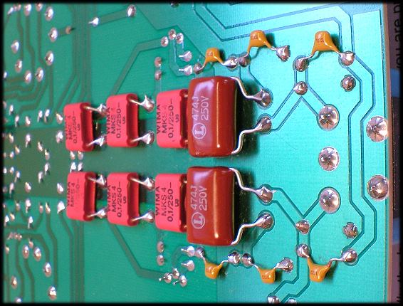 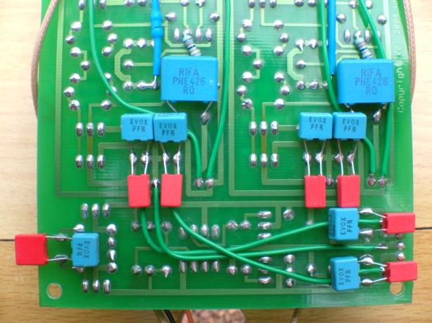 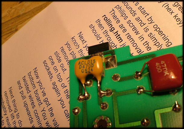 |
|
darynalexander
100+
will probably give you some sort of disease.
Posts: 179
|
Post by darynalexander on Dec 29, 2006 0:14:26 GMT
Perfect, Mike, and thank you for all of the information that made this new addiction possible. I have a lot of stuff to practice on, so I think I'll be okat when Hungary finally gets its act together. I have TONS of double sided tape and every type of glue in the world (don't ask why), plus i have lots of sockets to try out before I go after the opamp in the Heed. Less chance of overheating everything that way.
Also, the sig on the board is awesome.
Thanks again, you kick ass.
Daryn
|
|
rickcr42
Fully Modded
Rest in peace my good friend.
Posts: 4,514
|
Post by rickcr42 on Dec 29, 2006 0:18:36 GMT
Told ya.I leave all the fiddly shit to the guy with the patience and skills to do it.I am more of a "beat it in with a hammer then close the lid quick" type. Or put another way I am the meat to mike's side dish (damn that does not sound exactly the way it is meant to ),i give you the steak,him the garnish |
|


 )
)

 )
) )
) ) I am ready to rock !

 Here's a few pics of some bypassing, hopefully they'll give you the idea.... just remember to physically attach them to the PCB first and then solder..... double sided sellotape is ideal.