Deleted
Deleted Member
Posts: 0
|
Post by Deleted on Jun 23, 2015 21:30:27 GMT
|
|
Deleted
Deleted Member
Posts: 0
|
Post by Deleted on Jun 23, 2015 21:31:28 GMT
this is my 1st HTPC build
bit off topic I know .. but I have a second one about 70% complete currently ..
|
|
Deleted
Deleted Member
Posts: 0
|
Post by Deleted on Jun 23, 2015 21:33:34 GMT
Nick Not only do SSDs sound slightly better for Audio, they improve markedly with SQ if powered via a regulated supply. Even using a LM317T to convert the internal +12V to +5V gives an improvement. Further gains result when followed by a JLH PSU add-on. Powering the internal writer via a dual JLH (+12V and +5V) results in improved SQ rips , despite the checksums remaining the same. !!! My reports have been confirmed by Martin Colloms of HiFi Critic magazine.(6 separate Blind A/B/A 3 minute tests)
Alex
|
|
|
|
Post by PinkFloyd on Jun 23, 2015 21:36:16 GMT
Are you on the booze?
|
|
Deleted
Deleted Member
Posts: 0
|
Post by Deleted on Jun 23, 2015 21:37:54 GMT
who me or sandyk
me nope .. just getting tired
|
|
Deleted
Deleted Member
Posts: 0
|
Post by Deleted on Jun 23, 2015 21:39:26 GMT
Nick Not only do SSDs sound slightly better for Audio, they improve markedly with SQ if powered via a regulated supply. Even using a LM317T to convert the internal +12V to +5V gives an improvement. Further gains result when followed by a JLH PSU add-on. Powering the internal writer via a dual JLH (+12V and +5V) results in improved SQ rips , despite the checksums remaining the same. !!! My reports have been confirmed by Martin Colloms of HiFi Critic magazine.(6 separate Blind A/B/A 3 minute tests)
Alex
Hi Alex .. yes great advice, I may try all this on my 3rd HTPC build .. thanks for the post |
|
|
|
Post by PinkFloyd on Jun 23, 2015 21:44:52 GMT
Both of you. I'm off to bed. |
|
Deleted
Deleted Member
Posts: 0
|
Post by Deleted on Jun 23, 2015 22:26:19 GMT
I haven't even had breakfast yet! I can't remember the last time I had some of that lovely Scotch sitting in a cupboard that Will sent me either. |
|
Deleted
Deleted Member
Posts: 0
|
Post by Deleted on Jun 24, 2015 18:59:43 GMT
Come on Mike you still in bed ....  |
|
jc
Fully Modded
Posts: 5,417 
|
Post by jc on Jun 24, 2015 20:24:15 GMT
I will post some pics tomorrow after work Let's be seeing it then. I've been incommunicado for a week and thought you'd be harassing Mike with some awesomeness like the HTPC build you linked to  @ Mike, I like the capacitance sub-board, good bit of lateral thinking there. Definitely taking general notes here, never know when they may come in handy. |
|
Deleted
Deleted Member
Posts: 0
|
Post by Deleted on Jun 24, 2015 20:45:47 GMT
Ok every one some photos as promised .. not as advanced as mike but proof at least that I have started the build nevertheless !! first picture of the audio skunk works !!  second picture of new 2oz copper pcb with new gerber file on cad (100% as per original) this is the power supply  3rd pic of my secret weapon arsenal .. he he  some pics of the started pcb build .. a little late I know    more to follow ..... great site every one |
|
jc
Fully Modded
Posts: 5,417
|
Post by jc on Jun 24, 2015 21:11:21 GMT
Excellent! I like the summer house retreat too...
|
|
Deleted
Deleted Member
Posts: 0
|
Post by Deleted on Jun 24, 2015 21:19:57 GMT
I remember that thread . I noticed at the time that he was using the case designed for a Silicon Chip amplifier.
|
|
Deleted
Deleted Member
Posts: 0
|
Post by Deleted on Jun 24, 2015 21:26:13 GMT
yep good memory ... 2nd HTPC in progress .. yet to finish the silicon chip magazine studio 350 amp but am keen to do so, as I heard one the other day from a local friend, and I quite liked it
regards
Nick
|
|
Deleted
Deleted Member
Posts: 0
|
Post by Deleted on Jun 24, 2015 22:32:58 GMT
yep good memory ... 2nd HTPC in progress .. yet to finish the silicon chip magazine studio 350 amp but am keen to do so, as I heard one the other day from a local friend, and I quite liked it regards Nick Nick With the Studio 350, assuming you have selected well matched pairs for both of the 2SA1084 and BF469 , Tweak the value of the 6.8K slightly to give as close as possible to 0mV between the 2 4.7K collector resistors when warmed up with the 100 ohm trimpot set to dead centre.(as measured) If the reading increases with a much higher (>10 x) resistor in parallel with the 6.8K you may need to increase the value of the 6.8K slightly.
Regards Alex
|
|
|
|
Post by PinkFloyd on Jun 25, 2015 7:51:15 GMT
Looking good Nick  Have you got any of the green terminal connectors going spare? |
|
Deleted
Deleted Member
Posts: 0
|
Post by Deleted on Jun 25, 2015 11:14:33 GMT
sure .. which ones
or all that you see on the board ??
|
|
|
|
Post by PinkFloyd on Jun 25, 2015 11:58:36 GMT
sure .. which ones or all that you see on the board ?? Just two of the 5 way ones Nick................ |
|
Deleted
Deleted Member
Posts: 0
|
Post by Deleted on Jun 25, 2015 17:10:38 GMT
sure .. with pleasure
I will pop a few in the post for you ..
Nick
|
|
|
|
Post by PinkFloyd on Jun 25, 2015 18:34:33 GMT
sure .. with pleasure I will pop a few in the post for you .. Nick Cheers Nick, That's very good of you mate. |
|
|
|
Post by PinkFloyd on Jun 25, 2015 18:37:39 GMT
Alex,
High or low HFE?
I have four matched TIP41C with HEF of 55 and 4 matched with HFE of 150...... what would you tend to go with in this amp, the lower or the higher HFE? I'm thinking the higher would be a better bet but you know a lot more about transistors than I ever will.
Mike.
|
|
Deleted
Deleted Member
Posts: 0
|
Post by Deleted on Jun 25, 2015 22:06:04 GMT
Alex, High or low HFE? I have four matched TIP41C with HEF of 55 and 4 matched with HFE of 150...... what would you tend to go with in this amp, the lower or the higher HFE? I'm thinking the higher would be a better bet but you know a lot more about transistors than I ever will. Mike. Hi Mike I would go with the higher gain TIP41C. It means less loading on the previous stage, which is good, as long as it remains stable.
Regards Alex
|
|
|
|
Post by PinkFloyd on Jun 26, 2015 19:40:51 GMT
It seems to be taking for fekkin' ever to put this thing together If I had all the parts to hand I could easily populate BOTH boards in about 4 hours...... anyhoo, that's the TIP41c matched transistors and heatsinks fitted so pretty much just awaiting the enclosure now: 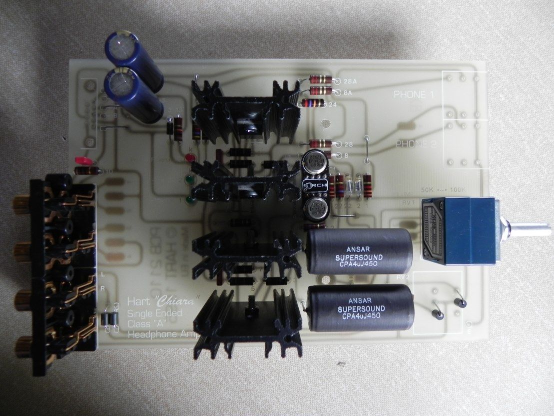 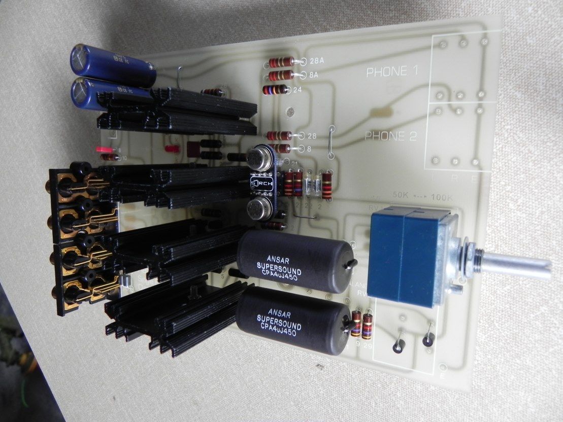 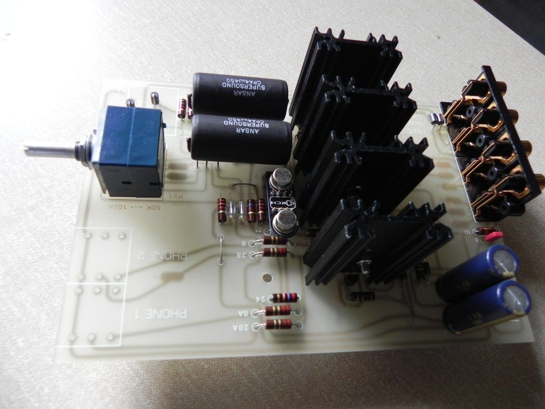 The pot and RCA sockets are for illustrative purposes only and will not feature in the build "proper". Doesn't look like much does it? It's only when you see the amp and power board side by side that it starts to put some meat on the bones: 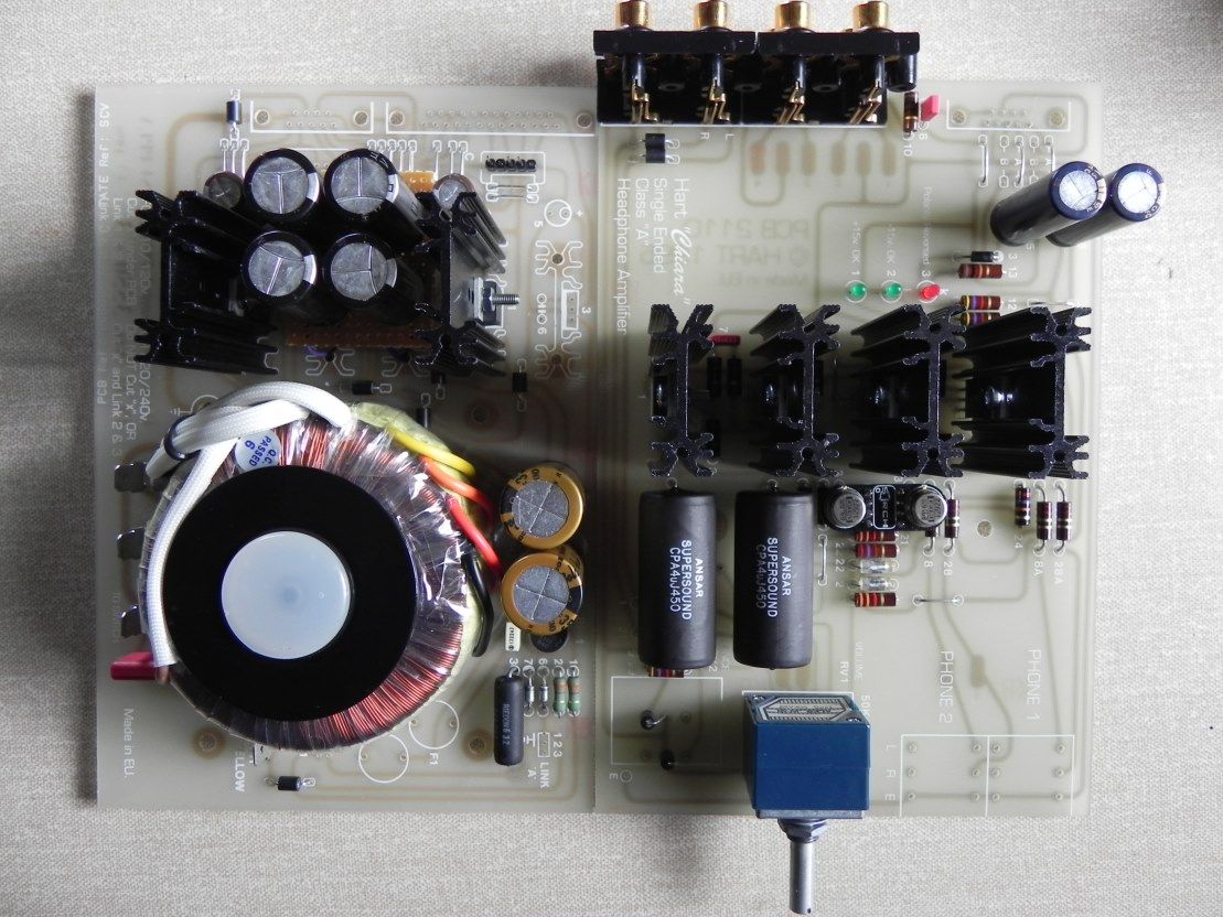 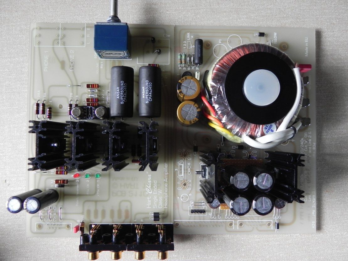 Pair it with a few randoms and it looks even meatier 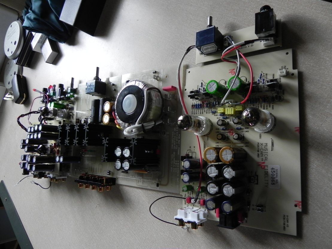 The bottom of the board is old fashioned but ever so easy to work with..... your through hole pads are all fine and dandy but if you want to desolder a part they can be a right royal bastard to work with..... these old fashioned types are a lot more forgiving of "constant" parts swapping.... if you are really ham fisted and manage to lift a pad or two it's not a problem as you simply solder the part direct to the track, no need to scrape it down to copper:  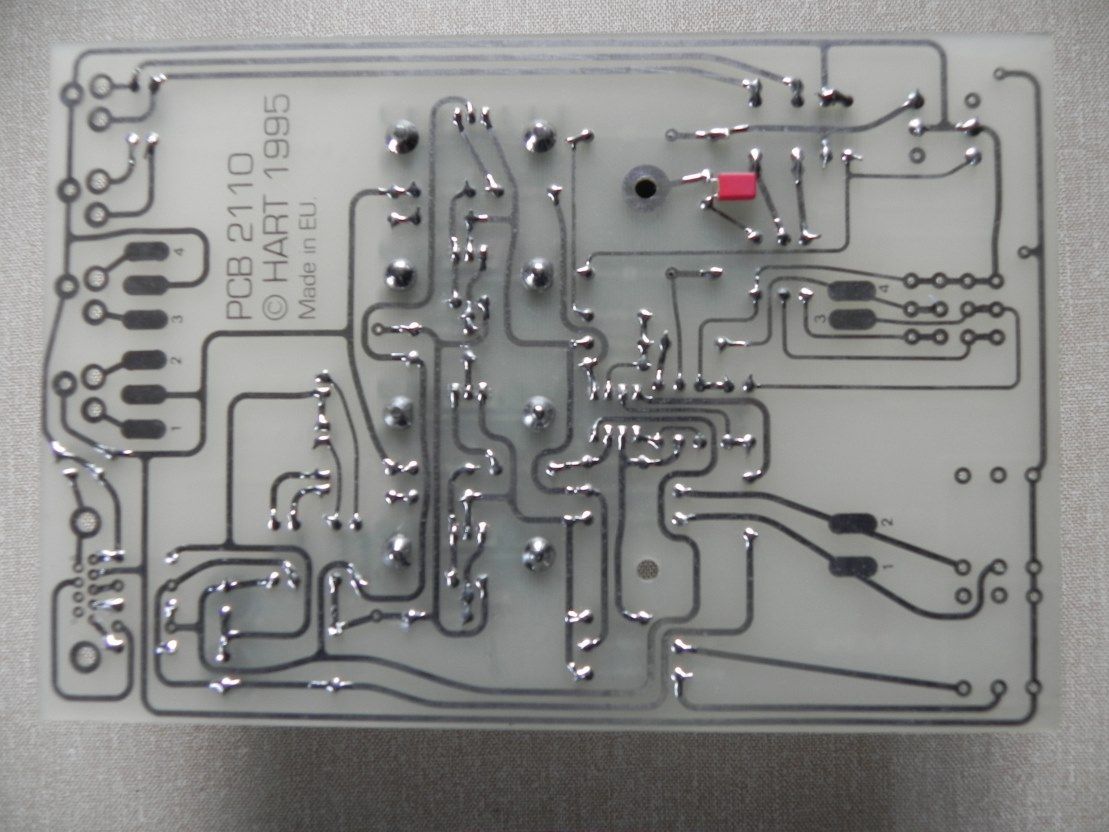 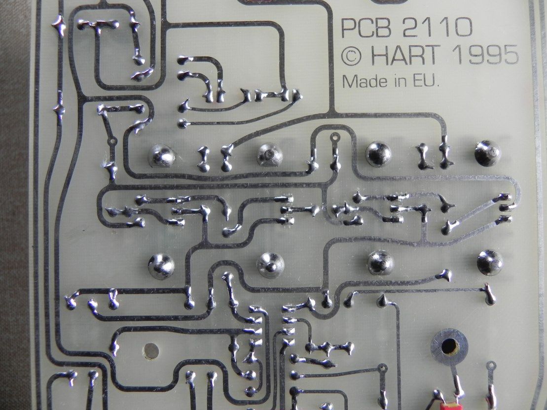 |
|
Deleted
Deleted Member
Posts: 0
|
Post by Deleted on Jun 26, 2015 19:53:02 GMT
well done looking good ... yes mike I love the old layout boards (single sided) with my new 2oz copper tracks very forgiving for the builder, as they can take some heat and abuse etc
no surface mount stuff for me ..
plus more room as you say to experiment with part / values and different size components etc. I used to like the old Elektor boards that where published .. just like could old valve stuff
|
|
|
|
Post by PinkFloyd on Jun 26, 2015 20:03:45 GMT
Jesus....... I must visit the optician again..... those solder joints on the Dip8 socket look a bit suss...... the top two: It's probably just the camera angle but I am very particular when it comes to my soldering..... |
|


 Have you got any of the green terminal connectors going spare?


