Deleted
Deleted Member
Posts: 0
|
Post by Deleted on Aug 23, 2011 0:26:04 GMT
Hi All well embarrassed as i am with 25years of DIY behind me  I've never soldered surface mount components. i like a new challenge but i guess the big thing is knowing where to start.  I've had a trawl through the Net and found a few sites (hey these are all robots).  i did find one with a nice video tutorial which was pretty useful and gave some idea of tools required.I'll post a link for that later. but lets face it, it's way different to through hole soldering.  so i was wondering if anyone with real life experience would care to share it with newbies like me.  so far I'm just at the gathering tools stage. tools Antex Iron (i chose this one because it has a large range of bit options) a board clamp (to keep a nice firm grip on things) an illuminated bench to magnifier some 0.015 solder liquid flux (that's a new one on me) curved tweezers a set of loops (x3 x5 x10) eye transplant ;D i was wondering about flux paste. is it useful? what type would people recommend? if any of you old hands have a tool which makes them think ''if only I'd had this when i started it would have been sooooo much easier'' it would be great to know. any info would save me from despair here to learn  take care |
|
Deleted
Deleted Member
Posts: 0
|
Post by Deleted on Aug 23, 2011 0:42:19 GMT
ditto
|
|
XTRProf
Fully Modded
Pssst ! Got any spare capacitors ?
Posts: 5,689
|
Post by XTRProf on Aug 23, 2011 4:25:36 GMT
For a start, it's not SMC, it's SMD. Btw, we don't service SMT PCBAs due to the labour hours involved and not economically viable. It's meant to be scrapped as most SMT PCBAs are quite cheap to produce. That's more than 15 years ago. Anyway, everytime it scare me much ($$$ wise) to take the scrap authorisation form (for all scraps) for the American VPs to sign to effect scraps every quarter. I'm not sure now and other PCBA plants. I'm talking of HDD SMT PCBAs.  Sorry, I can't disclose the figure although I'm not working there any more for years. |
|
Deleted
Deleted Member
Posts: 0
|
Post by Deleted on Aug 23, 2011 8:21:34 GMT
For a start, it's not SMC, it's SMD. Btw, we don't service SMT PCBAs due to the labour hours involved and not economically viable. It's meant to be scrapped as most SMT PCBAs are quite cheap to produce. That's more than 15 years ago. Anyway, everytime it scare me much ($$$ wise) to take the scrap authorisation form (for all scraps) for the American VPs to sign to effect scraps every quarter. I'm not sure now and other PCBA plants. I'm talking of HDD SMT PCBAs. Sorry, I can't disclose the figure although I'm not working there any more for years. Hi Chong thanks for the correction I've modified the thread title accordingly. yes i think you may be right.when i re clocked my Marantz CD17KIS i needed to remove a few CMD and it was pretty tricky.  however I'm hoping that soldering them to a board may be easier.  take care |
|
Deleted
Deleted Member
Posts: 0
|
Post by Deleted on Aug 23, 2011 8:29:26 GMT
|
|
XTRProf
Fully Modded
Pssst ! Got any spare capacitors ?
Posts: 5,689
|
Post by XTRProf on Aug 23, 2011 8:46:39 GMT
If it's any use, here is a few. 1) Since it's all robotics, we use uv solder paste as solder. But for manual, the flux paste is not required. Just use the normal liquid flux will do the job. 2) You guys better have good steady hands as we are talking of real tiny copper pads and traces in SMD. When you are not careful, a lot of traces and pads could be lifted during SMD removing for those with lots of leads.  3) It will be good if you can use a small amount of glue to stick the SMDs and orientate the SMDs on the PCB before soldering. This is done at the solder pasting stage before auto insert stage which we don't see. 4) I dun quite agreed with him on using a fatter tip then a slimmer tip. 5) Ah, now they have chip quick solder. That's a great product. We don't have that more than 15 years ago. Where can I find some? Generally, the video guide is very good. But they didn't mention the level of competency and dexterity required. Also, it assumes you have good eyes with no cataract.  |
|
|
|
Post by PinkFloyd on Aug 23, 2011 9:18:16 GMT
|
|
|
|
Post by PinkFloyd on Aug 23, 2011 9:22:52 GMT
When soldering SMD chips the "easiest" way is to use normal solder (nothing else).... use a relatively large bit.... flood the solder across the legs (vertical drag) and then apply sole desolder braid and sweep across it.... this will suck ALL the solder from the surface and ONLY leave a solder join between pad and leg.... a VERY tidy way to do it |
|
Deleted
Deleted Member
Posts: 0
|
Post by Deleted on Aug 23, 2011 9:37:44 GMT
Hi Mike thanks for the above link which looks like a good way of working with those kind of chips. i did notice that he was wetting the joints before soldering which was interesting. thanks for the info take care Hi Chong ''2) You guys better have good steady hands as we are talking of real tiny copper pads and traces in SMD. When you are not careful, a lot of traces and pads '' you may be right and i could end up being pretty hopeless but we all need to start somewhere. when i start to think on doing something new i always try to ask those with experience. more chance of success that way. I'm one of those people who think that if it can be done then with a little effort i can do it too. I've asked the question to find out for myself and maybe help others in the same greenhorn spot. take care |
|
|
|
Post by PinkFloyd on Aug 23, 2011 9:41:27 GMT
There's a very good video on here somewhere (Rick linked to it) I'll see if I can find it.
Mike.
|
|
Deleted
Deleted Member
Posts: 0
|
Post by Deleted on Aug 23, 2011 9:45:59 GMT
When soldering SMD chips the "easiest" way is to use normal solder (nothing else).... use a relatively large bit.... flood the solder across the legs (vertical drag) and then apply sole desolder braid and sweep across it.... this will suck ALL the solder from the surface and ONLY leave a solder join between pad and leg.... a VERY tidy way to do it Hi Mike thanks again for sharing that. I've heard of the flood and suck thing before so it's nice to have a practical explanation. it just takes all of the mystery out of that technique. i guess that the only thing to watch is that the wick does not cool toooo quickly and start ripping up pads. so fast work required on that. i also noticed that Chong recommends using glue to fix IC's to the board prior to soldering. I've read that before so any comments would be really useful. I've wanted to learn how to work with SMD for some time now so all advice is useful. it opens up a whole new world of possibilities for me thanks for the info take care |
|
XTRProf
Fully Modded
Pssst ! Got any spare capacitors ?
Posts: 5,689
|
Post by XTRProf on Aug 23, 2011 9:51:42 GMT
Good luck! Don't forget SMD can overheat quite fast as they are very small. |
|
|
|
Post by PinkFloyd on Aug 23, 2011 10:09:32 GMT
Good luck! Don't forget SMD can overheat quite fast as they are very small. Hence the large bit... in and out FAST |
|
|
|
Post by Garage1217 on Aug 23, 2011 16:13:13 GMT
I solder around 100-400 SMD's a week at the office and for my business. I can share my tips and tricks for quick and clean work... For removal of most all components:I use a 1.5mm chisel tip attached to a variable 70W iron set at 350C. I quickly heat the solder and then use a solder sucker to remove most all of the solder from the side(s) of the component. I then heat one side for around 3 seconds while gently prying up on the component. Said component will lift on one side, and the heat transfer will make the solder soft enough on the other side, it does not lift the pad. I have never lifted a pad doing it this way and I solder on a constantly 0603, 0805, 1206, plcc-2, 5050 / plcc-6 and many other forms. I personally never use braid as I cannot stand it but to each his own. Re-install a component or place a new component:Once the component is removed, I re-heat - melt the solder and again on the pad at 350C use my solder sucker to remove anything left on the pad. I modified the tip of my solder sucker to allow the iron to be under it slightly, giving it a decent seal, but with enough airflow to create good suction. This results in a glass smooth pad in a very quick step. Once the pad is prepped, or if it is a new pad, I will barely tin one pad only. Using spring loaded tweezers that hold the component tight, preventing accidental drops, I quickly heat the pad and attach one component side so the tinned pad This secures it without using glue. I then use the appropriate size solder for what I am doing and apply a bit to each side of the component making sure it flows to the pad and to the legs of the component itself. I keep heat on the component & pad for 2 seconds at 300C to ensure the quality of the joint vs. going to a lower temp and keeping heat on longer. Soldering rather heat sensitive leds this way, I have around 1 failure in 1000 or more which could have been an out of box failure as I am careful to avoid heat damage. I have had 0 resistors or other components damaged this way. Maybe I am just lucky  Some examples of my work. Taken long ago, my current work looks even better. 0603 next to a plcc2 that I replaced.  Some through hole work. These pins are attached to an LCD which was removed, and then re-soldered. With through hole, I only use a solder sucker as well and avoid braid.  When I get a chance I will do a step by step photo document of how I solder smd's on a new or old board per my description above. If anyone cares, I can link you to the exact equipment I use, but will not post it here as people can be very partial to their solder stations and everyone always considers theirs the best, and appropriately so. If you solder a lot, you damn near form a bond with your equipment lol |
|
Deleted
Deleted Member
Posts: 0
|
Post by Deleted on Aug 23, 2011 21:35:21 GMT
Hi garage1217 well I'm green with envy. you guys just make things looks so easy. : thats a great post and really nice work and yes a link to your preferred equipment would be interesting. we all have our likes and dislikes. it would be nice to have as many experiences and ideas as possible. that way anyone looking for answers can choose what suits them best. no room for my preciouses here it's all good information. my take is this i may muck it up but thats not the point. it's trying, learning and hopefully getting there in the end that matter to me. so post away your experience is most welcome thanks a step by step guide would also be great and help my learning experience. take care |
|
Deleted
Deleted Member
Posts: 0
|
Post by Deleted on Aug 24, 2011 1:24:56 GMT
Aye Jeremy, a most welcome idea, soldering SMDs is a bit of a black art to me! I await your guide |
|
|
|
Post by Garage1217 on Sept 16, 2011 15:30:20 GMT
A quick writeup I did on how to solder a 4 leg smd to the project sunrise amp. Did a quick write up on how to solder an SMD like the single plcc-4 provided with the Sunrise kit. What you need:- The solder of your choice, small diameter is important. I recommend around a .020 to .030 max - Spring loaded tweezers are highly recommended - A good soldering iron with a small chisel tip around 1.5mm / set to around 275C depending on the type of solder you use. - Magnifying glass if you need one What to remember:- LED's do not like a ton of heat. - Do not keep the iron on the led for more than 3 seconds at a time - A little solder goes a LONG way with SMD work. I actually went a little overkill in these pics but needed to so it stands out in the photos The notch on the board has to be aligned properly... 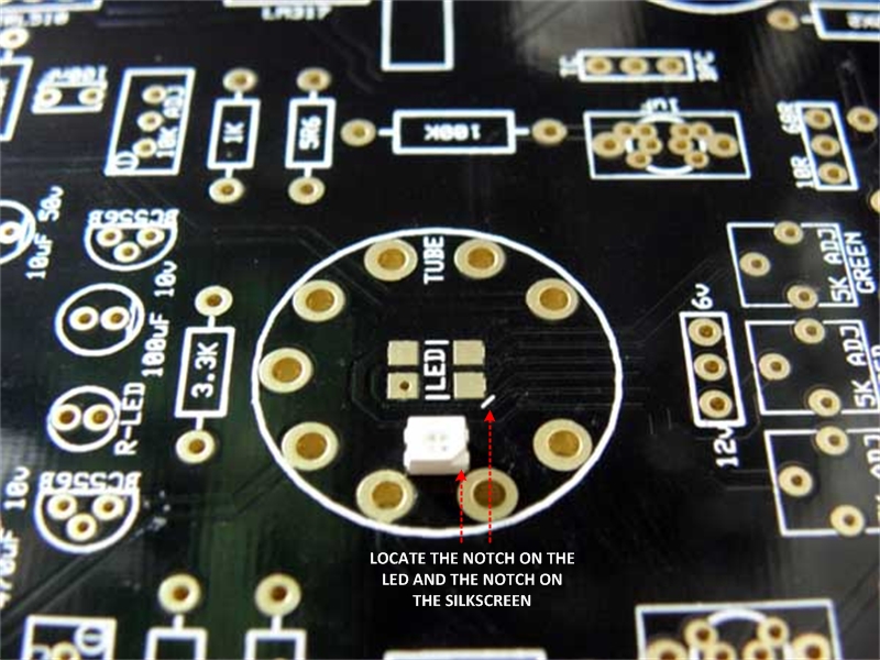 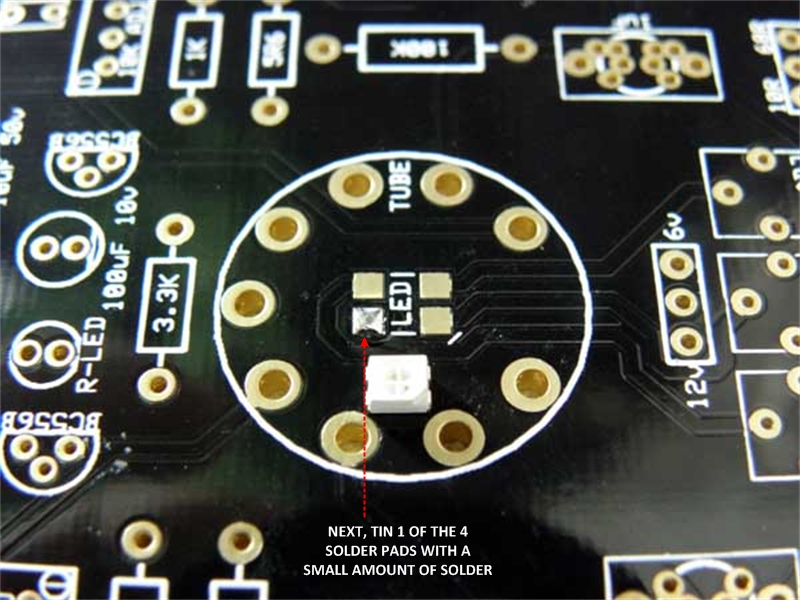 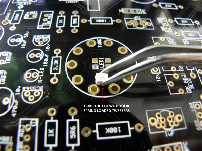 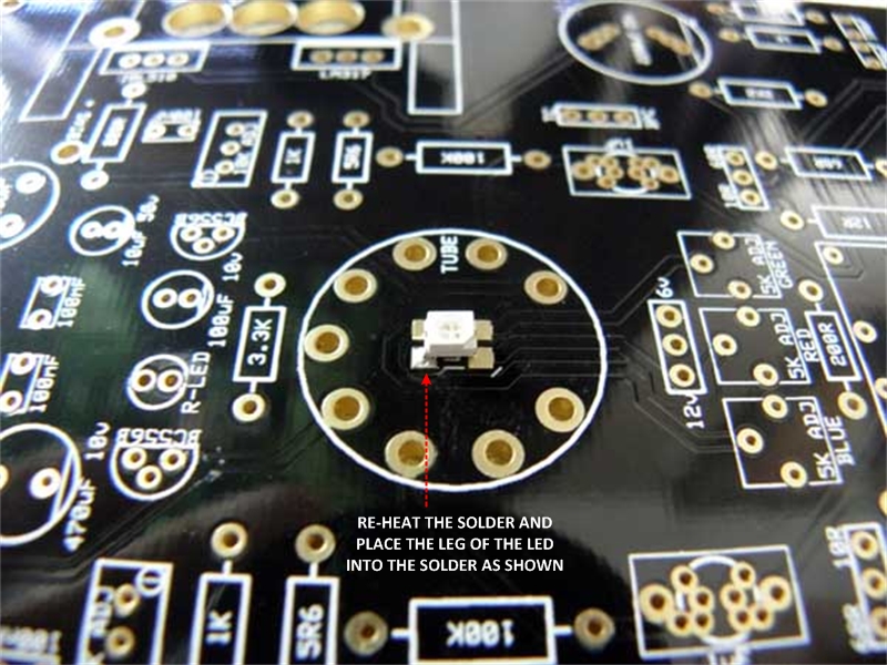  Finished once each leg is soldered 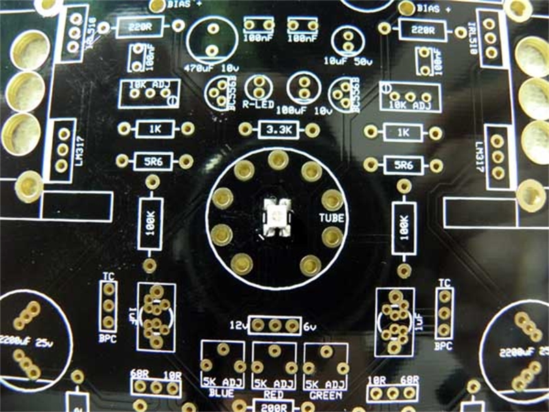 |
|